Table of Contents
Advertisement
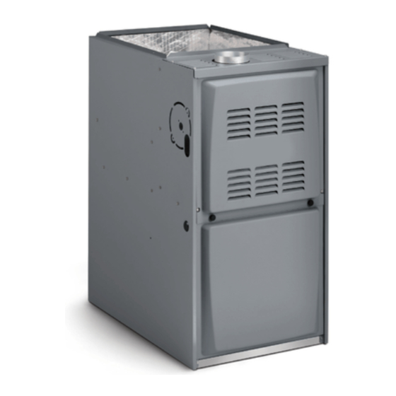
Upflow / Horizontal Left and Right Air Discharge
This is a safety alert symbol and should never be ignored. When you see this symbol on labels or in
manuals, be alert to the potential for personal injury or death.
As with any mechanical equipment, personal injury can
result from contact with sharp sheet metal edges. Be
careful when you handle this equipment.
Unit Dimensions ..........................................................2
Parts Arrangement.......................................................3
80G2UH-V Gas Furnace .............................................4
Shipping and Packing List ...........................................4
Safety Information .......................................................4
General ........................................................................5
Combustion, Dilution & Ventilation Air .........................6
Setting Equipment .......................................................8
Filters .........................................................................11
Manufactured By
Allied Air Enterprises LLC
A Lennox International, Inc. Company
215 Metropolitan Drive
West Columbia, SC 29170
507335-02
INSTALLATION INSTRUCTIONS
80G2UH-V
Warm Air Gas Furnace
This manual must be left with the homeowner for future reference.
WARNING
Table of Contents
Save these instructions for future reference
Improper installation, adjustment, alteration, service
or maintenance can cause property damage, personal
injury or loss of life. Installation and service must be
performed by a licensed professional installer (or
equivalent), service agency or the gas supplier.
Duct System ..............................................................11
Gas Piping .................................................................22
Electrical ....................................................................24
Adjusting Airflow ........................................................28
Start-Up .....................................................................29
Maintenance ..............................................................35
Control Diagnostics ...................................................36
Planned Service ........................................................37
Repair Parts List ........................................................37
*P507335-02*
Issue 2001
WARNING
(P) 507335-02
Page 1 of 39
Advertisement
Table of Contents

Related Manuals for Allied 80G2UH070AV12


Summary of Contents for Allied 80G2UH070AV12
-
Page 1: Table Of Contents
Setting Equipment ............8 Planned Service ............37 Filters .................11 Repair Parts List ............37 Manufactured By *P507335-02* Allied Air Enterprises LLC A Lennox International, Inc. Company 215 Metropolitan Drive (P) 507335-02 West Columbia, SC 29170 Save these instructions for future reference 507335-02... -
Page 2: Unit Dimensions
Unit Dimensions 3-1/8 (79) SUPPLY AIR FLUE OUTLET OPENING (Top) OPTIONAL 23-3/4 EXTERNAL (603) SIDE RETURN AIR FILTER KIT (635) (Either Side) TOP VIEW 3/4 (19) 27-3/4 (705) Front Panel 3-1/4 (83) 9/16 19-7/16 3 (76) Right 9/16 (14) (14) (494) 6-3/4 (171) Left FLUE OUTLET... -
Page 3: Parts Arrangement
Parts Arrangement HEAT EXCHANGER COMBUSTION AIR INDUCER COMBUSTION AIR INDUCER PRESSURE SWITCH ROLLOUT LOCATED INSIDE VALVE BURNER BOX CABINET BURNER CONTROL (INCLUDES INTEGRATED CONTROL, AND TRANSFORMER) BURNER ACCESS PANEL BLOWER ACCESS BLOWER PANEL ASSEMBLY Figure 1. 507335-02 Issue 2001 Page 3 of 39... -
Page 4: 80G2Uh-V Gas Furnace
Clearances 80G2UH-V Gas Furnace Adequate clearance must be made around the air openings into the vestibule area. In order to ensure proper unit The 80G2UH-V gas furnace is shipped ready for operation, combustion and ventilation air supply must be installation in the upflow or horizontal position (left or right). provided according to the current National Fuel Gas Code. -
Page 5: General
Return air temperature EQUIPMENT LIMITED WARRANTY. ALLIED must not exceed 85° F (29°C) dry bulb. DISCLAIMS ALL LIABILITY IN CONNECTION WITH INSTALLER’S FAILURE TO FOLLOW THE ABOVE This furnace may be installed in alcoves, closets, attics, INSTALLATION INSTRUCTIONS. -
Page 6: Combustion, Dilution & Ventilation Air
• Place the furnace as close to the center of the air fireplaces, exhaust fans, or clothes dryers are used at the distribution system as possible. The furnace should same time as the furnace, much more air is necessary to also be located close to the chimney or vent termination ensure proper combustion and to prevent a downdraft. - Page 7 Confined Space Air from Outside A confined space is an area with a volume less than 50 If air from outside is brought in for combustion and cubic feet (1.42 m3) per 1,000 Btu (.29 kW) per hour of ventilation, the confined space must have two permanent the combined input rating of all appliances installed in that openings.
-
Page 8: Setting Equipment
Setting Equipment WARNING Do not install the furnace on its front or its back. Do not connect the return air ducts to the back of the furnace. Doing so will adversely affect the operation of the safety control devices, which could result in personal injury or death. - Page 9 Type of Vent Type C Type B1 Connector 1 in. (25 mm) 1 in. (25 mm) Figure 9. Single Side Return Air * Front 2-1/4 in. (57 mm) 2-1/4 in. (57 mm) (with transition and filter) Back Sides 0† Removing the Bottom Panel Vent 6 in.
- Page 10 Horizontal Applications The furnace can be installed in horizontal applications. Order horizontal suspension kit (51W10) or use equivalent suspension method. Allow for clearances to combustible materials as indicated on the unit nameplate. Minimum clearances for closet or alcove installations are shown in Figure 11. This furnace may be installed in either an attic or a crawl Type of Vent Type C...
-
Page 11: Filters
WARNING Improper installation of the furnace can result in personal injury or death. Combustion and flue products must never be allowed to enter the return air system or the living space. Use screws and joint tape to seal the return air system to the furnace. In platform installations with bottom return air, the furnace should be sealed airtight to the return air plenum. - Page 12 Supply Air Plenum If the furnace is installed without a cooling coil, a removable access panel must be installed in the supply air duct. The access panel should be large enough to permit inspection (either by smoke or reflected light) of the heat exchanger for leaks after the furnace is installed.
- Page 13 • Disconnect pressure switch hose from barbed fitting on the pressure switch assembly. Remove pressure switch assembly • Remove make-up box assembly (2 screws) and cut wire tie to (1 screw) and cut wire tie to free pressure switch wires. Reinstall free make-up box wires.
- Page 14 The venting tables in this manual were extracted from the National Fuel Gas Code (NFPA 54 / ANSI Z223.1) and are provided as a guide for proper vent installation. Proper application, termination, construction and location of vents must conform to local codes having jurisdiction. In the absence of local codes, the NFGC serves as the defining document.
- Page 15 DO NOT insulate the space between the liner and the Masonry chimneys used to vent Category I central furnaces must be either tile lined or lined with a listed metal lining chimney wall with puffed mica or any other loose granular system or dedicated gas vent.
- Page 16 Never connect a Category I appliance to a chimney that is Maximum Horizontal Connector Diameter servicing a solid fuel appliance. If a fireplace chimney flue Connector Length in. (mm) is used to vent this appliance, the fireplace opening must ft. (m) be permanently sealed.
- Page 17 20. The common vent diameter must always be at least as Close all building doors and windows and all doors large as the largest vent connector diameter. between the space in which the appliances remaining connected to the common venting system are located 21.
- Page 18 Capacity of Type B Double Wall Vents with Type B Double Wall Connectors Serving a Single Category I Appliance Vent and Connector Diameter - D (inches) 3 inch 4 inch 5 inch 6 inch Height H Lateral L (feet) (feet) Appliance Input Rating in Thousands of Btu per Hour NOTE: Single appliance venting configurations with zero lateral lengths are assumed to have no elbows in the vent system.
- Page 19 Capacity of Type B Double Wall Vents with Single Wall Metal Connectors Serving a Single Category I Appliance Vent and Connector Diameter - D (inches) 3 inch 4 inch 5 inch 6 inch Height H Lateral L (feet) (feet) Appliance Input Rating in Thousands of Btu per Hour NOTE: Single appliance venting configurations with zero lateral lengths are assumed to have no elbows in the vent system.
- Page 20 Vent Connector Capacity Type B Double Wall Vents with Type B Double Wall Connectors Serving Two or More Category I Appliances Vent and Connector Diameter - D (inches) Vent Connector 3 inch 4 inch 5 inch 6 inch Height H Rise R Appliance Input Rating in Thousands of Btu per Hour (feet)
- Page 21 Vent Connector Capacity Type B Double Wall Vents with Single Wall Metal Connectors Serving Two or More Category I Appliances Vent and Connector Diameter - D (inches) Vent 3 inch 4 inch 5 inch 6 inch Lateral L Height H (feet) Appliance Input Rating in Thousands of Btu per Hour (feet)
-
Page 22: Gas Piping
The piping should be sloped 1/4 inch (6.4 mm) per Gas Piping 15 feet (4.57 m) upward toward the meter from the furnace. The piping must be supported at proper intervals [every 8 to 10 feet (2.44 to 3.01 m)] with suitable hangers or straps. - Page 23 Left Side Piping Right Side Piping (Standard) (Alternate) AUTOMATIC AUTOMATIC GAS VALVE MANUAL GAS VALVE MANUAL (with manual MAIN SHUT-OFF (with manual MAIN SHUT-OFF VALVE shut-off valve) VALVE shut-off valve) GROUND JOINT UNION GROUND JOINT UNION DRIP LEG DRIP LEG FIELD PROVIDED AND INSTALLED...
-
Page 24: Electrical
Leak Check Electrical After gas piping is completed, carefully check all piping connections (factory and field installed) for gas leaks. Use a leak detecting solution or other preferred means. ELECTROSTATIC DISCHARGE (ESD) Precautions and Procedures NOTE: If emergency shutoff is necessary, shut off the main manual gas valve and disconnect the main power to the furnace. - Page 25 Refer to Figure 44 for schematic wiring diagram and Install the room thermostat according to the instructions troubleshooting and Figure 43 for field wiring. provided with the thermostat. If the furnace is being matched with a heat pump, refer to the instruction The power supply wiring must meet Class I restrictions.
- Page 26 Connect a sufficiently sized wire with ground to the Terminals are provided on the integrated ignition/blower furnace’s line voltage connections and ground wire. Refer control board for connection to a 120-volt humidifier. The to the furnace rating plate for electrical characteristics “HUM”...
- Page 27 Circulating Airflow Adjustments Continuous Blower Operation Cooling Mode The comfort level of the living space can be enhanced when using this feature by allowing continuous circulation The units are factory set for the highest airflow for each of air between calls for cooling or heating. The circulation model.
-
Page 28: Adjusting Airflow
Model Stage Setting Setting Setting Setting Setting Setting Setting Setting Adjustment* Norm 1026 1105 1225 80G2UH070AV12 Norm Norm 1013 1079 1130 1390 1200 1405 1600 80G2UH090BV16 Norm 1033 1271 1090 * Speed Adjustment (+) or (-) 10% by moving jumper from NORM. -
Page 29: Start-Up
Allowable Heating Speeds Model Speed Adjust Setting "D" Setting "C" Setting "B" Setting "A" +10% Allowed Allowed Allowed Not Allowed 80G2UH070AV12 Norm Allowed Allowed Factory Setting Allowed -10% Allowed Allowed Allowed Allowed +10% Allowed Allowed Allowed Not Allowed 80G2UH090BV16 Norm... - Page 30 Gas Valve Operation 10. Turn ON all electrical power to the unit. See Figure 33 and Figure 34 11. Set the thermostat to desired setting. NOTE: When unit is initially started, steps 1 through STOP! Read the safety information at the beginning 11 may need to be repeated to purge air from gas line.
- Page 31 Manifold Pressure Gas Meter Clocking Chart Seconds for One Revolution NOTE: A pressure test adapter kit is available to facilitate Natural manifold pressure measurement. Capacity 1 cu ft 2 cu ft 1 cu ft 2 cu ft 1. Connect test gauge to manifold pressure tap (Figure Dial Dial Dial...
- Page 32 High Altitude Thermostat Heat Anticipation The manifold pressure, gas orifice and pressure switch Set the heat anticipator setting (if adjustable) according to may require adjustment or replacement to ensure proper the amp draw listed on the wiring diagram that is attached operation at higher altitudes.
- Page 33 Two Stage Cooling In the event the unit loses ignition, the control will attempt to recycle up to five times before it goes into a 1 hour A call for 1st stage cooling from the thermostat closes the lockout. Lockout may be manually reset by removing R to Y circuit on the control board.
- Page 34 Figure 35. Indoor Blower Operation - 1st Stage-2nd Stage (W1/W2) Heat Call Figure 38. Indoor Blower Operation - Single Stage Cooling Figure 36. Indoor Blower Operation - High Heat (W2) Call * Percentage of High Stage Cooling Figure 37. Indoor Blower Operation - Call for Fan * Percentage of High Stage Cooling Figure 39.
-
Page 35: Maintenance
Filters Maintenance All filters are installed external to the unit. Filters should be inspected monthly. Clean or replace the filters when necessary to ensure that the furnace operates properly. Replacement filters must be rated for high velocity airflow. WARNING Table 1 lists recommended filter sizes. ELECTRICAL SHOCK, FIRE, OR EXPLOSION HAZARD Flue and Chimney... -
Page 36: Control Diagnostics
High Heat State LED Control Diagnostics On 80G2UH-V models, a green LED is provided on the control board to indicate high heat state (see Table 18). Troubleshooting CFM LED Make the following visual checks before troubleshooting: On 80G2UH-V models equipped with a variable speed Check to see that the power to the furnace and the motor, an amber LED is provided on the control board to integrated ignition/blower control board is ON. -
Page 37: Planned Service
Planned Service The following items should be checked during an annual inspection. Power to the unit must be shut off for the service technician’s safety. Fresh air grilles and louvers (on the unit and in the Operating performance - Unit must be observed during room where the furnace is installed) - Must be open and operation to monitor proper performance of the unit and unobstructed to provide combustion air. - Page 38 Figure 43. Typical Field Wiring Diagram Page 38 of 39 Issue 2001 507335-02...
- Page 39 Figure 44. Wiring Schematic 507335-02 Issue 2001 Page 39 of 39...
Need help?
Do you have a question about the 80G2UH070AV12 and is the answer not in the manual?
Questions and answers