Table of Contents
Advertisement
Quick Links
This is a safety alert symbol and should never be ignored. When you see this symbol on labels or in manuals, be alert to
the potential for personal injury or death.
Improper installation, adjustment, alteration, service
or maintenance can cause property damage, personal
injury or loss of life. Installation and service must be
performed by a licensed professional installer (or
equivalent), service agency or the gas supplier.
As with any mechanical equipment, personal injury can
result from contact with sharp sheet metal edges. Be
careful when you handle this equipment.
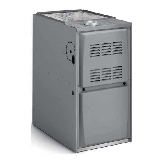
80G2DFE Gas Furnace
The 80G2DFE gas furnace is shipped ready for installation
in the downflow position fueled by natural gas. A conversion
kit (ordered separately) is required for use in LP/ Propane
gas applications.
Manufactured By
Allied Air Enterprises LLC
215 Metropolitan Drive
West Columbia, SC 29170
508145-01
INSTALLATION INSTRUCTIONS
Warm Air Gas Furnace
Downflow Air Discharge
This manual must be left with the homeowner for future reference.
WARNING
CAUTION
80G2DFE
80G2DFE Gas Furnace ............................................. 1
Unit Dimensions ........................................................ 2
Parts Arrangement..................................................... 3
Shipping and Packing List ......................................... 4
Safety Information ..................................................... 4
General ...................................................................... 6
Combustion, Dilution & Ventilation Air ....................... 6
Downflow Installation ................................................. 9
Filters ........................................................................11
Duct System .............................................................11
Venting..................................................................... 12
Gas Piping ............................................................... 17
Electrical .................................................................. 19
Integrated Control DIP Switch Settings ................... 27
On-Board Links and Diagnostic Push Button .......... 27
Unit Start-Up ............................................................ 28
Other Unit Adjustments............................................ 31
Heating Sequence of Operation .............................. 31
Service..................................................................... 32
Repair Parts List ...................................................... 34
Blower Performance ................................................ 35
Issue 2128
Table of Contents
*P508145-01*
(P) 508145-01
Page 1 of 36
Advertisement
Table of Contents

Subscribe to Our Youtube Channel
Related Manuals for Allied 80G2DFE


Summary of Contents for Allied 80G2DFE
-
Page 1: Table Of Contents
Repair Parts List ............34 80G2DFE Gas Furnace Blower Performance ..........35 The 80G2DFE gas furnace is shipped ready for installation in the downflow position fueled by natural gas. A conversion kit (ordered separately) is required for use in LP/ Propane gas applications. -
Page 2: Unit Dimensions
Unit Dimensions 3-1/8 9/16 (79) (14) RETURN AIR OPENING FLUE OUTLET 19-7/16 9/16 (Top) (494) (14) 9/16 (14) TOP VIEW 1-1/2 (38) 27-3/4 (705) Front Panel 19-7/16 9/16 9/16 (14) (494) (14) AIR FLOW ELECTRICAL INLET (Either Side) (838) 5-3/8 (137) Right GAS PIPING INLET 2-3/16 (56) Left (Either Side) -
Page 3: Parts Arrangement
Parts Arrangement Top Cap Secondary Limit Indoor Blower Control Box (includes integrated control, transformer and door switch) Internal Flue Pipe Assembly Heat Exchanger Combustion Air Inducer Burner Box Assembly Primary Limit Gas Valve Figure 1. 508145-01 Issue 2128 Page 3 of 36... -
Page 4: Shipping And Packing List
Certifications Shipping and Packing List These units are CSA International certified to ANSI Z21.47. In the USA, installation of gas furnaces must conform with 1 - Assembled Gas Furnace local building codes. In the absence of local codes, units 1 - Bag assembly containing the following: must be installed according to the current National Fuel 2 - Screws Gas Code (ANSI-Z223.1). - Page 5 VOIDS MANUFACTURER’S upflow or horizontal position. EQUIPMENT LIMITED WARRANTY. ALLIED DISCLAIMS ALL LIABILITY IN CONNECTION WITH This furnace design has not been CSA certified for INSTALLER’S FAILURE TO FOLLOW THE ABOVE installation in mobile homes, recreational vehicles, or INSTALLATION INSTRUCTIONS.
-
Page 6: General
ENTITIES. ALL SUCH POLICIES AND CODES MUST BE In the absence of local codes concerning air for combustion ADHERED TO. and ventilation, use the guidelines and procedures in this section to install these furnaces to ensure efficient and safe operation. You must consider combustion air needs and requirements for exhaust vents and gas piping. - Page 7 In addition to providing combustion air, fresh outdoor air dilutes contaminants in the indoor air. These contaminants may include bleaches, adhesives, detergents, solvents and other contaminants which can corrode furnace components. The requirements for providing air for combustion and ventilation depend largely on whether the furnace is installed in an unconfined or a confined space.
- Page 8 NOTE: Each air duct opening shall have a free area of at least one NOTE: The inlet and outlet air openings shall each have a free square inch per 2,000 Btu (645 mm² per .59 kW) per hour of the area of at least one square inch per 4,000 Btu (645 mm²...
-
Page 9: Downflow Installation
Front to Rear Side to Side Cabinet Units with 1/2 or 3/4 HP Blower Motor Width A (14-1/2”) 19-3/4 13-1/4 B (17-1/2”) 19-3/4 16-1/4 RIGID LEG remove shipping bolt and washer NOTE - Floor opening dimensions listed are 1/4 inch (6 mm) larger than the unit opening. - Page 10 Return Air Opening -- Downflow Units Front to Rear Side to Side Cabinet The following steps should be taken when installing Width plenum: A (14-1/2”) 15-3/4 1. Bottom edge of plenum should be flanged with a B (17-1/2”) 18-3/4 hemmed edge (see Figure 11). Table 2.
-
Page 11: Filters
Downflow Application Filters Allow for clearances to combustible materials as indicated on the unit nameplate. Minimum clearances for closet or This unit is not equipped with a filter or rack. A field provided alcove installations are shown in Figure 14. high velocity filter is required for the unit to operate properly. -
Page 12: Venting
The vent connector does not require insulation. Figure 16. The 80G2DFE series units are classified as fan-assisted Use self-drilling sheet metal screws or a mechanical Category I furnaces when vertically vented according to... - Page 13 If the existing chimney will not accommodate a listed meta • The vent connectors and chimney are sized according liner, either the chimney must be rebuilt to accommodate to the provided venting tables. one of these liners or an alternate approved venting method must be found.
- Page 14 General Venting Requirements If the common vertical vent is offset, the maximum common vent capacity listed in the common venting Vent all furnaces according to these instructions: tables should be reduced by 20%, the equivalent 1. Vent diameter recommendations and maximum of two 90°...
- Page 15 21. When connecting this appliance to an existing dedicated or common venting system, you must inspect the venting system’s general condition and look for signs of corrosion. The existing vent pipe size must conform to these instructions and the provided venting tables. If the existing venting system does not meet these requirements, it must be resized. Capacity of Type B Double Wall Vents with Type B Double Wall Connectors Serving a Single Category I Appliance Vent and Connector Diameter - D (inches) Height...
- Page 16 Vent Connector Capacity Type B Double Wall Vents with Type B Double Wall Connectors Serving Two or More Category I Appliances Vent and Connector Diameter - D (inches) Vent Connector 3 inch 4 inch 5 inch 6 inch Height Rise Appliance Input Rating in Thousands of Btu per Hour (feet) (feet)
-
Page 17: Gas Piping
Removal of the Furnace from Common Vent Follow the lighting instructions. Turn on the appliance that is being inspected. Adjust the thermostat so that In the event that an existing furnace is removed from the appliance operates continuously. a venting system commonly run with separate gas appliances, the venting system is likely to be too large to After the burners have operated for 5 minutes, test for properly vent the remaining attached appliances. - Page 18 Gas Pipe Capacity - FT³/HR (kL/HR) Internal Length of Pipe - feet (m) Nominal Iron Diameter Pipe Size - - inches inches (mm) (3.048) (6.096) (9.144) (12.192) (15.240) (18.288) (21.336) (24.384) (27.432) (30.480) (mm) .622 (12.7) (17.799) (4.87) (3.34) (2.69) (2.29) (2.03) (1.84)
-
Page 19: Electrical
IMPORTANT CAUTION When testing pressure of gas lines, gas valve must be Failure to use properly sized wiring and circuit breaker disconnected and isolated. See Figure 20. Gas valves may result in property damage. Size wiring and circuit can be damaged if subjected to pressures greater than breaker(s) per Technical Specification and unit rating 1/2 psig (3.48 kPa, 14 inches w.c.). - Page 20 Thermostat Electrically ground the unit according to local codes or, in the absence of local codes, according to the current Install the room thermostat according to the instructions National Electric Code (ANSI/NFPA No. 70). A green provided with the thermostat. See Table 9 for thermostat ground wire is provided in the field make-up box.
- Page 21 COMFORT SYNC ® THERMOSTAT 070-12 090-16 Figure 22. Wiring Diagram 508145-01 Issue 2128 Page 21 of 36...
- Page 22 DIP Switch Settings and On-Board Links Thermostat Wiring Connections DIP Switch 1 On Board Links Must Be Cut To Select System Options FURNACE OUTDOOR T'STAT TERM. STRIP UNIT 1 Heat / 1 Cool NOTE: Use DIP DO NOT CUT ANY switch 2 to set ON-BOARD LINKS sceond-stage heat...
- Page 23 DIP Switch Settings and On-Board Links Thermostat Wiring Connections DIP Switch 1 On Board Links Must Be Cut To Select System Options FURNACE OUTDOOR T'STAT TERM. STRIP UNIT 2 Heat / 2 Cool CUT ON-BOARD LINK W915 2 STAGE COMPR *Not required on all units FURNACE OUTDOOR...
- Page 24 DIP Switch Settings and On-Board Links Thermostat Wiring Connections DIP Switch 1 On Board Links Must Be Cut To Select System Options FURNACE HEAT PUMP TERM. STRIP T'STAT CUT ON-BOARD LINK 67M41* W951 Dual Fuel Single- HEAT Stage Heat Pump PUMP Thermostat w/dual fuel capabilities...
- Page 25 DIP Switch Settings and On-Board Links Thermostat Wiring Connections DIP Switch 1 On Board Links Must Be Cut To Select System Options FURNACE HEAT PUMP TERM. STRIP T'STAT Dual Fuel Single- 67M41* Stage Heat Pump CUT ON-BOARD LINK Thermostat w/dual W951 fuel capabilities HEAT...
- Page 26 24VAC Indoor Ignitor and Combustion Blower Terminals Air Inducer Neutrals Flame Sense S4 DIP Switches Diagnostic Push Button On Board Links 3/16” QUICK CONNECT TERMINALS THERMOSTAT CONNECTIONS (TB1) DS = DEHUMIDIFICATION SIGNAL FLAME SENSE SIGNAL W2 = HEAT DEMAND FROM 2ND STAGE T/STAT HI Cool 24VAC W1 = HEAT DEMAND FROM 1ST STAGE T/STAT HI HEAT 24VAC...
-
Page 27: Integrated Control Dip Switch Settings
Integrated Control DIP Switch Settings Switch 3 Switch 4 Seconds 80G2DFE units are equipped with a two-stage integrated control. This control manages ignition timing, heating 90 (factory) mode fan off delays and indoor blower speeds based on selections made using the control dip switches and jumpers. -
Page 28: Unit Start-Up
On-Board Link W951 Heat Pump (R to O) BEFORE LIGHTING smell all around the appliance area for gas. Be sure to smell next to the floor because some On-board link W951 is a clippable connection between gas is heavier than air and will settle on the floor. terminals R and O on the integrated control. - Page 29 Is the unit ignition system in lock out? If the unit locks NOTE: Pressure test adapter kit (10L34) is available from out again, call the service technician to inspect the unit Allied Air to facilitate manifold pressure measurement. for blockages. 1. Connect test gauge to manifold pressure tap (Figure 10.
- Page 30 Table 14 shows acceptable combustion for For safety, shut unit off and remove manometer as soon all 80G2DFE models. The maximum carbon monoxide as an accurate reading has been obtained. Take care to reading should not exceed 100 ppm.
-
Page 31: Other Unit Adjustments
This manually reset switches are located on the baffle The two-stage, variable speed integrated control used plate in the burner assembly. in 80G2DFE units has an added feature of an internal Watchguard control. The feature serves as an automatic Pressure Switch... -
Page 32: Service
If second-stage heat is required, the thermostat After the 20-second warm-up period has ended, the second- stage heat contacts close and send a signal to gas valve is energized on low fire (first stage) and the integrated control. The integrated control initiates ignition occurs. - Page 33 At the beginning of each heating season, and to comply disconnecting the indoor blower. For additional details, with the Allied Air Limited Warranty, your system should please see Service and Application Note H049. be checked as follows:...
-
Page 34: Repair Parts List
• Flame sensor independent Allied Air dealers. When ordering parts, include the complete furnace model number listed on • Heat exchanger assembly the CSA International nameplate. All service must be • Gas manifold performed by a licensed professional HVAC installer (or •... -
Page 35: Blower Performance
Blower Performance 80G2DF070AE12 Performance (Less Filter) Air Volume / Watts at Various Blower Speeds External Static High Medium - High Medium Medium - Low Pressure (Black) (Brown) (Blue) (Yellow) (Red) in. w.c. watts watts watts watts watts 0.00 1475 1345 1190 0.10 1440... - Page 36 Requirements for Commonwealth of Massachusetts Modifications to NFPA-54, Chapter 10 INSPECTION. The state or local gas inspector of the side wall, horizontally vented, gas-fueled equipment Revise NFPA-54 section 10.8.3 to add the following shall not approve the installation unless, upon requirements: inspection, the inspector observes carbon monoxide For all side wall, horizontally vented, gas-fueled equipment...
Need help?
Do you have a question about the 80G2DFE and is the answer not in the manual?
Questions and answers