Advertisement
Quick Links
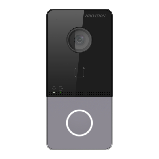
DS-KV61X3-(W)PE1
Video Intercom Villa Door Sta on
UD20195B-B
ENGLISH
Diagram References
1
Appearance
1
Microphone
2
Camera
3
Indicator
4
Bu on
5
Card Reading Area
6
Loudspeaker
7
Terminals
8
Debugging Port
9
TAMPER
10
Set Screw
11
TF Card Slot
12
Network Interface
Note: The debugging port is used for debugging only.
Indicator Descrip on
Unlock: Green
Call: Orange
Communicate: White
2
Terminal and Wiring
NC: Door Lock Relay Output (NC)
485-: RS-485 Interface (Reserved)
NO: Door Lock Relay Output (NO)
485+: RS-485 Interface (Reserved)
COM: Common Interface
12 VDC IN: Power Supply Input
AIN1: For the access of Door Contact
GND: Grounding
AIN3: For the access of Exit Bu on
AIN2&AIN4: Reserved
3
Installa on Accessory
1
2
Moun ng Template
Moun ng Plate
Note: The dimension of the moun ng plate is 102.58 mm × 39.24 mm × 6.2 mm.
4
Installa on
Note: Video intercom villa door sta on supports surface moun ng.
Before You Start
Make sure all related equipments are power-off during the installa on.
Tools that you need to prepare for installa on:
Drill (ø2.846) and gradienter.
Purchase the protec ve shield before installa on.
Surface Moun ng without Protec ve Shield
1. S ck the moun ng template on the wall. Drill screw holes according to the moun ng
template. Remove the template from the wall.
2. Secure the moun ng plate on the wall with 4 supplied screws according to the screw
holes.
3. Install the villa door sta on to the moun ng plate. Fix the device on the moun ng
plate with the set screw.
Surface Moun ng with Protec ve Shield
1. S ck the moun ng template on the wall. Drill the screw holes according to the
moun ng template. Remove the template from the wall.
2. Align the protec ve shield with the moun ng template.
3. Secure the moun ng plate and protec ve shield on the wall with 4 supplied screws
according to the screw holes.
4. Install the villa door sta on to the moun ng plate. Fix the device on the moun ng
plate with the set screw.
5
Configura on via Web
1
Ac vate Device via Web
You are required to ac vate the device first by se ngs a strong password before you
can use the device.
Default parameters of door sta on are as follows:
Default IP Address: 192.0.0.65.
Default Port No.:8000.
Default User Name: admin
1. Power on the device, and connect the device to the network.
2. Enter the IP address into the address bar of the web browser, and click Enter to enter
the ac va on page.
Note: The computer and the device should belongs to the same subnet.
3. Create and enter a password into the password field.
4. Confirm the password.
5. Click OK to ac vate the device.
Note: When the device is not ac vated, the basic opera on and remote configura on of device cannot be
performed.
2
Access to the Device by Web Browsers
1. In the browser address bar, enter the IP address of the device, and press the Enter
key to enter the login page.
2. Enter the user name and password and click Login.
3
Communicate with Indoor Sta on
1. Click Se ngs -> Intercom -> Press Bu on to Call to enter the se ngs page.
2. Set the parameters.
- Edit call No. for every bu on.
- Check Call Management Center to set the bu on calling center.
Note: If you check Call Management Center and set the call No. as well, call management center has
higher privilege than call No.
3. Press bu on to call indoor sta on.
4
Issue Card
1. Click Se ngs -> Access Control and Elevator Control to enter the se ngs page.
2. Click Issue Card. Present the card on the card reading area.
3. When issuing finished, the windows pop up on the se ngs page.
Note:
Only Mifare card supported, and Mifare card with non-standard shape is recommended.
Up to 10000 cards can be issued and managed by V series door sta on. A voice prompt (No more cards
can be issued.) can be heard when the issued card amount exceeds the upper limit.
5
Unlock Door
A er issuing cards, you can unlock the door by presen ng the issued cards.
Refers to Video Intercom Villa Door Sta on User Manual (scan the QR code) for details.
The simplified declaration of conformity
Hereby, Hangzhou Hikvision Digital Technology Co., Ltd. ("Hikvision") declares that
the DS-KV6113-WPE1 device complies with the requirements of Directive 2014/53 / EU of
the European Parliament and of the Council of April 16, 2014 on the harmonization of
the laws of the Member States relating to making radio equipment available on the
market and repealing Directive 1999/5 / EC. The full text of the declaration of
conformity is available at the Hikvision website
h p://www.hikvisioneurope.com/portal
Industry Canada ICES-003 Compliance
This device meets the CAN ICES-3 (B)/NMB-3(B) standards requirements.
For RED-Direc ve 2014/53/EU
The frequency, mode and the maximum transmi ed power in EU are listed below:
Model
Received frequency
Transmi ed frequency
Bandwidth
Frequency power
802.11b:16dBm +/- 1.5dBm
DS-KV6113-
802.11g:15dBm +/- 1.5dBm
2.4 to 2.4835GHz
2.4 to 2.4835GHz
20 to 40MHz
WPE1
802.11n(ht20):14dBm +/- 1.5dBm
802.11n(ht40):12dBm +/- 1.5dBm
1 1
DS-KV6103-PE1
DS-KV6113-WPE1
1
2
3
4
4
Surface Moun ng without Protec ve Shield
Villa Door Station
2
3
Screw
Screws
Mounting Plate
Surface Moun ng with Protec ve Shield
Screws
Villa Door Station
3
4
Screw
Screws
Mounting Plate
Protective Shield
11
5
6
7
8
9
10
3
1
Mounting Template
Wall
1
2
Mounting Template
Wall
2
Orange
Yellow
Red
12
Black
White
White
White
White
Yellow
Green
Blue
Black
Black
39.24
1
1
1
Hole
Hole
102023104
The recommended distance from the ground level is 1.40
adjustable depends on the height of body.
1
1
Hole
Hole
2
Hole
RS-485+
Reserved
RS-485-
12 VDC
Power
Input
GND
AIN1
AIN2
AIN3
AIN4
NC
Exit Button
COM
PRESS
NO
TO EXIT
GND
GND
3.45
1.18
2
Unit : mm
6.2
Advertisement

Related Manuals for HIKVISION DS-KV61 3-PE1 Series


Summary of Contents for HIKVISION DS-KV61 3-PE1 Series
- Page 1 Refers to Video Intercom Villa Door Sta on User Manual (scan the QR code) for details. The simplified declaration of conformity Hereby, Hangzhou Hikvision Digital Technology Co., Ltd. ("Hikvision") declares that the DS-KV6113-WPE1 device complies with the requirements of Directive 2014/53 / EU of...
- Page 2 ENGLISH ENGLISH ENGLISH ENGLISH ENGLISH ENGLISH FRANÇAIS DEUTSCH ESPAÑOL ITALIANO Références du schéma Diagram References Diagram References Verweise auf Schaubilder Diagram References Diagram References Referencias del diagrama Diagram References Diagram References Riferimento schemi Apparence Au au Apariencia Aspe o Mikrofon Kamera Micrófono Cámara...
- Page 3 Uwaga: Aby uzyskać informacje dotyczące konfiguracji, skorzystaj z podręcznika użytkownika. Uproszczona deklaracja zgodności Niniejszym Hangzhou Hikvision Digital Technology Co., Ltd. (“Hikvision”) oświadcza, że urządzenie DS-KV6113-WPE1 spełnia wymagania dyrektywy Parlamentu Europejskiego i Rady 2014/53/UE z dnia 16 kwietnia 2014 r. w sprawie harmonizacji ustawodawstw państw członkowskich dotyczących udostępniania na rynku urządzeń...
- Page 4 ©2020 Hangzhou Hikvision Digital Technology Co., Ltd. Alle rechten voorbehouden. e gli altri mar chi e loghi di Hikvision sono di pr o prietà di Hikvision in v arie giurisdizioni. Gli altri mar c hi registra e loghi menziona appartengono ai...
Need help?
Do you have a question about the DS-KV61 3-PE1 Series and is the answer not in the manual?
Questions and answers