Table of Contents
Advertisement
Quick Links
JUICE ULTRA - Operation Instructions and Installation Guide
Version 1-3A
Content
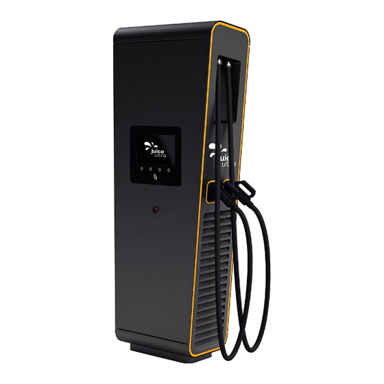
JUICE ULTRA (75kW – 300kW)
ultra-fast charging system for electric vehicles
IMPORTANT:
Read this manual before you start using the device!
Failure to comply with these instructions may result in injury or death, damage
to the device and harm to the environment.
Keep the manual in a safe place for future reference.
All rights reserved. The reproduction of this document, also partially, is allowed only with authorization by alpitronic s.r.l.
Operation Instructions
and Installation Guide
Version 1-3A | 3.0
Advertisement
Table of Contents

Related Manuals for Juice ULTRA


Summary of Contents for Juice ULTRA
- Page 1 JUICE ULTRA - Operation Instructions and Installation Guide Version 1-3A Content Operation Instructions and Installation Guide JUICE ULTRA (75kW – 300kW) ultra-fast charging system for electric vehicles Version 1-3A | 3.0 IMPORTANT: Read this manual before you start using the device! Failure to comply with these instructions may result in injury or death, damage to the device and harm to the environment.
- Page 2 JUICE ULTRA - Operation Instructions and Installation Guide Version 1-3A Content All rights reserved. The reproduction of this document, also partially, is allowed only with authorization by alpitronic s.r.l.
- Page 3 JUICE ULTRA - Operation Instructions and Installation Guide Version 1-3A Content Operation Instructions and Installation Guide Version Version 1-3A of operation instructions and installation guide, 25 January 2019 Original English version © 2019 alpitronic S.r.l. All rights reserved. The reproduction of this document, also partially, is allowed only with authorization by alpitronic S.r.l.
-
Page 4: Table Of Contents
JUICE ULTRA base positioning ..............38 4.1.5. JUICE ULTRA base ..................40 4.2. Electrical installation ....................42 4.2.1. JUICE ULTRA schematic for the double slot version ........42 4.2.2. JUICE ULTRA schematic for the quadruple slot version ........43 4.2.3. Preparation mains power-supply cables ............44 4.2.4. - Page 5 Figure 21: Unpacking the JUICE ULTRA ................32 Figure 22: Relevant components for the mechanical installation of the JUICE ULTRA ..34 Figure 23: Cable reach for the two DC outlets of the JUICE ULTRA .........35 Figure 24: Recommended distances for site configuration ..........37 Figure 25: Distances between base plate and outer dimensions of charging station on the concrete foundation double slot version (display/top view) ..........38...
- Page 6 Table 8: AC input switchgear components for JUICE ULTRA quadruple slot version ..28 Table 9: Dimension of the packaging ................29 Table 10: Maximum weight and threat size for eyebolts for different JUICE ULTRA product types ..........................29 Table 11: Distances to keep free for service ..............37 Table 12: Distances between base plate and outer dimensions of charging station ..39...
-
Page 7: Safety Instructions
JUICE ULTRA ultra-fast charging system. 1.1. Designated use The JUICE ULTRA ultra-fast charging system for electric vehicles is intended to be used both in indoor and outdoor environments for performing ultra-fast charging for electric vehicles. - Page 8 Before performing any installation, disassembly, repair or replacement of components, switch off the external group switch and the main switch in the JUICE ULTRA cabinet and do a voltage check to make sure that the electrical power is disconnected from the system.
- Page 9 The JUICE ULTRA power-stacks will be turned off. To turn off the JUICE ULTRA, one can find the main switch (see Figure 28) in the cabinet, rotate the handle to position ‘0’. This will turn off all internal components of the JUICE ULTRA.
-
Page 10: Product Description
Version 1-3A Page 10 of 72 2 Product description 2. Product description For the JUICE ULTRA charging stations product family two different housings are available, which can be equipped with various options shown in the following table: Options Model DC-Power Charging Interfaces (see chapter 2.2) -
Page 11: Figure 1: Double Slot Version With One (Left) And Two (Right) Power-Stacks
JUICE ULTRA - Operation Instructions and Installation Guide Version 1-3A 2 Product description Page 11 of 72 As shown in the following picture the double slot version can be equipped with one or two power-stacks: Figure 1: double slot version with one (left) and two (right) power-stacks... -
Page 12: Figure 3: Quadruple Slot Version With One, Two, Three And Four Power-Stacks
JUICE ULTRA - Operation Instructions and Installation Guide Version 1-3A Page 12 of 72 2 Product description As shown in the following picture the quadruple slot version can be equipped with one, two, three or four power-stacks: Figure 3: quadruple slot version with one, two, three and four power-stacks... -
Page 13: Additional Options
2.1.3. Door contact switches In order to be able to recognize, when the JUICE ULTRA doors are open, there is the possibility to optionally order door contact switches integrated in the system. 2.1.4. JUICE ULTRA colors As standard, the JUICE ULTRA is delivered with the housing color Noire 2100 and the reflector strips on the door have the standard color Pantone 3115 C. -
Page 14: Dc-Power
DC-Power 75kW JUICE ULTRA power-stacks are used to supply the DC-charging cables installed on the JUICE ULTRA. One power-stack can supply only one DC-charging cable at the same time. The JUICE ULTRA power-stacks can be switched in parallel mode to increase the power conducted via one DC-charging cable. -
Page 15: Charging Interfaces
Version 1-3A 2 Product description Page 15 of 72 2.3. Charging interfaces The following charging interfaces can be selected for the JUICE ULTRA in various combinations: Charging interfaces Charging interface Max. Voltage capability [V] Max. current capability [A] CCS Combo 2 (not liquid 1.000V DC... -
Page 16: Nameplate
2.6. Opening of the JUICE ULTRA The JUICE ULTRA has three doors which allow access to the inside of the device. The service door and charging cable door are equipped with a locking cylinder to lock the device. All rights reserved. The reproduction of this document, also partially, is allowed only with authorization by alpitronic s.r.l. - Page 17 JUICE ULTRA - Operation Instructions and Installation Guide Version 1-3A 2 Product description Page 17 of 72 The cylinder is a ‘10/30 mm profile half cylinder’ which can be replaced by a customer-owned one. All rights reserved. The reproduction of this document, also partially, is allowed only with authorization by alpitronic s.r.l.
-
Page 18: Figure 9: Order For Opening The Juice Ultra Doors
2° open charging cable door 3° open display door 1° open service door Figure 8: Order for opening the JUICE ULTRA doors All rights reserved. The reproduction of this document, also partially, is allowed only with authorization by alpitronic s.r.l. -
Page 19: Figure 10: Locking Mechanism For The Display Door
JUICE ULTRA - Operation Instructions and Installation Guide Version 1-3A 2 Product description Page 19 of 72 The display door can be opened with the release of the locking mechanism behind the charging cable door, see following picture. Figure 9: Locking mechanism for the display door... -
Page 20: Internal View
-FB2 -TB1 -QB1 -QB1 Figure 10: Internal view JUICE ULTRA double slot version (service-, display-, charging cable - side) The following table describes the single components highlighted in the figures above: Identifier Description DC fault current monitoring for AC charging (optional, only when AC-socket is... -
Page 21: Table 3: Juice Ultra Double Slot Version Cabinet Components
-XD7 AC socket (optional, only when AC-socket is present) -XF1 RJ45 ethernet network-socket Table 3: JUICE ULTRA double slot version cabinet components All rights reserved. The reproduction of this document, also partially, is allowed only with authorization by alpitronic s.r.l. -
Page 22: Figure 12: Dc Output Switchgear Of The Double Slot Version (Bottom View)
JUICE ULTRA - Operation Instructions and Installation Guide Version 1-3A Page 22 of 72 2 Product description The following figure shows the DC-output switchgear of the double slot version: DC-outlet 2 DC-outlet 1 -XD4.1 -XD4.2 -XD3.1 -XD3.2 -BE2 -BE1 -FC2.1 -FC2.2... -
Page 23: Figure 14: Ac Input Switchgear Of The Double Slot Version
DC-busbar + pole for vehicle cable connection XD6 (DC-outlet 2) DC-busbar – pole for vehicle cable connection XD6 (DC-outlet 2) -XD4.2 Table 4: DC output switchgear components for JUICE ULTRA double slot version The following figure shows the AC input switchgear of the double slot version: -TB1... -
Page 24: Quadruple Slot Version Internal View
-XF1 RJ45 ethernet network socket Table 5: AC input switchgear components for JUICE ULTRA double slot version 2.7.2. quadruple slot version internal view The following figure shows the JUICE ULTRA internal view for the quadruple slot version: -BX1.2 -SF3 -TF1 -SF2 -BX2.2... -
Page 25: Table 6: Juice Ultra Quadruple Slot Version Cabinet Components
DC charge outlet 1 -XD7 DC charge outlet 2 (optional) -XF1 Ethernet network-dose RJ45 Table 6: JUICE ULTRA quadruple slot version cabinet components All rights reserved. The reproduction of this document, also partially, is allowed only with authorization by alpitronic s.r.l. -
Page 26: Figure 16: Dc Output Switchgear Of The Quadruple Slot Version (Bottom View)
JUICE ULTRA - Operation Instructions and Installation Guide Version 1-3A Page 26 of 72 2 Product description The following figure shows the DC-output switchgear of the quadruple slot version: DC-outlet 1 DC-outlet 2 -XD3.2 -XD3.1 -XD4.2 -XD4.1 -BE1 -BE2 -FC1.2 -FC1.1... -
Page 27: Figure 18: Ac Input Switchgear Of The Quadruple Slot Version
DC-busbar + pole for vehicle cable connection XD6 (DC-outlet 2) DC-busbar – pole for vehicle cable connection XD6 (DC-outlet 2) -XD4.2 Table 7: DC output switchgear components for JUICE ULTRA quadruple slot version The following figure shows the AC input switchgear of the quadruple slot version: -XD1... -
Page 28: Table 8: Ac Input Switchgear Components For Juice Ultra Quadruple Slot Version
Auxiliary 24V power supply -XD1 Mains input busbars -XF1 RJ45 ethernet network socket Table 8: AC input switchgear components for JUICE ULTRA quadruple slot version All rights reserved. The reproduction of this document, also partially, is allowed only with authorization by alpitronic s.r.l. -
Page 29: Transport, Storage, Unpacking And Handling
4xM12 <750 c… number of charging interfaces Table 10: Maximum weight and threat size for eyebolts for different JUICE ULTRA product types All rights reserved. The reproduction of this document, also partially, is allowed only with authorization by alpitronic s.r.l. -
Page 30: Transport, Handling And Storage
Figure 18: Vertical transport with pallet truck or forklift In addition to the transport with a pallet truck or a forklift, the JUICE ULTRA can be moved using the two (double slot version housing) or four (quadruple slot version housing) crane eyelets which are located on top of the packaging. -
Page 31: Unpacking
Page 31 of 72 3.3. Unpacking It is recommended to transport the JUICE ULTRA to its final destination in its original packaging and unpack it there. The following illustrations show the sequence how to unpack the JUICE ULTRA: Unpacking the JUICE ULTRA... -
Page 32: Figure 21: Unpacking The Juice Ultra
The outer packaging is made of 100% recyclable wood, the inner packaging is made of plastic and must be disposed separately. *Attention Before loosening the mounting screws between the JUICE ULTRA and the pallet, the JUICE ULTRA must be protected against overturning. This protection must be maintained until final mounting to the foundation. -
Page 33: Juice Ultra Installation
4. JUICE ULTRA installation This chapter describes the mechanical and the electrical installation of the JUICE ULTRA. It is recommended to install the JUICE ULTRA according the following steps and related chapter in the following sections: Site configuration (see chapter 4.1.3) JUICE ULTRA base positioning (see chapter 4.1.4) -
Page 34: Juice Ultra Mechanical Installation
4.1.1. Relevant components for JUICE ULTRA installation The mounting of the JUICE ULTRA must be performed on a solid ground, this can be a concrete foundation or a concrete floor. When dimensioning the foundation, it’s recommended to perform a static load capacity analysis according to relevant norms. -
Page 35: Cable Reach
4.1.2. Cable reach In its default configuration, the JUICE ULTRA comes with a cable length of 350cm. The following figure shows the operating radius (3m) of the cables for the two DC outlets of the JUICE ULTRA. -
Page 36: Site Configuration
4 JUICE ULTRA installation 4.1.3. Site configuration When installing the JUICE ULTRA, it must be ensured to maintain a minimum distance from possible objects around the JUICE ULTRA, to allow adequate airflow, and space for possible service or maintenance operations. -
Page 37: Figure 24: Recommended Distances For Site Configuration
The following figure shows the recommended minimum distances which should be kept free during installation on site: Figure 23: Recommended distances for site configuration The figure above shows the JUICE ULTRA housing for the double slot version, the distances for the both housings can be found in the following table. Type... -
Page 38: Juice Ultra Base Positioning
JUICE ULTRA base positioning Once the position of the JUICE ULTRA is defined on the installation site according to 4.1.3 the position of the JUICE ULTRA base and the cable entries from the foundation have to be defined: The JUICE ULTRA base is to be arranged eccentrically to the charging station. The outer dimensions related to the center of the base plate are shown in Figure 24 for the double slot version. -
Page 39: Figure 26: Distances Between Base Plate And Outer Dimensions Of Charging Station On The Concrete Foundation Quadruple Slot Version (Display/Top View)
516 mm (± 3 mm) Table 12: Distances between base plate and outer dimensions of charging station The JUICE ULTRA base includes cable entry plate for the cable glands which must be defended at the order. All rights reserved. The reproduction of this document, also partially, is allowed only with authorization by alpitronic s.r.l. -
Page 40: Juice Ultra Base
18mm Figure 27: JUICE ULTRA-base for the quadruple slot version The JUICE ULTRA base has to be screwed together with the concrete foundation by min. 4x M12x30 screws and washers (M12 x 32mm / delivered together with the JUICE ULTRA). - Page 41 (details in chapter 4.2.3). Attention The use of the cable entry plate when mounting the JUICE ULTRA mains supply cables is mandatory. If the adaptor-plate not used it can happen that the JUICE ULTRA draws dust which can destroy the device.
-
Page 42: Electrical Installation
4.2. Electrical installation The dimensioning of the cables and the protection devices outside the JUICE ULTRA are to be done according the local regulations and in order to respect the technical specification of the JUICE ULTRA stated in chapter 8. -
Page 43: Juice Ultra Schematic For The Quadruple Slot Version
Version 1-3A 4 JUICE ULTRA installation Page 43 of 72 4.2.2. JUICE ULTRA schematic for the quadruple slot version The following figure shows the schematic of the JUICE ULTRA for the quadruple slot version: -XD10 -XD9 -XD8 -XD7 DC charging... -
Page 44: Preparation Mains Power-Supply Cables
4 JUICE ULTRA installation 4.2.3. Preparation mains power-supply cables After the JUICE ULTRA base is mounted (see chapter 4.1.5), the mains-side cables should be conducted through foundation and JUICE ULTRA-base. Then the mains-side cables should be fixed by tightening the cable gland. -
Page 45: Grid Connection
Page 45 of 72 4.2.4. Grid Connection The JUICE ULTRA charging stations can be used in supply networks of the type TT and TN- Attention The necessary protective measures against electric shock and other country-specific requirements must be taken into account. -
Page 46: Figure 33: Sideview Of The Input Busbars (Double Slot Version Left, Quadruple Slot Version Right)
JUICE ULTRA - Operation Instructions and Installation Guide Version 1-3A Page 46 of 72 4 JUICE ULTRA installation Figure 32: Sideview of the input Busbars (double slot version left, quadruple slot version right) If an active cooled Cable is used (option), the cooling unit for cooled charging cable should be removed during grid connection (see 7.3.). -
Page 47: Checks Before Initial Startup
JUICE ULTRA - Operation Instructions and Installation Guide Version 1-3A 4 JUICE ULTRA installation Page 47 of 72 4.2.5. Checks before initial startup The operation of this charging station must be carried out taking into account the test and maintenance instructions described below. All instructions listed below are considered mandatory and must be carried out by the operator of the charging station. -
Page 48: Diagnosis And Parameterization
JUICE ULTRA - Operation Instructions and Installation Guide Version 1-3A Page 48 of 72 5 Diagnosis and parameterization 5. Diagnosis and parameterization After successful mechanical and electrical installation of the charging station, the correct functioning of the device can be checked by means of a diagnostic and parameterization tool. -
Page 49: Figure 35: Home Screen Of Web Interface
‘Stop Button’ can be found. • To check the status of the JUICE ULTRA power-stacks, you can navigate to ‘STATUS’ from the main menu and then following the top menu ‘Stacks’ can be found. - Page 50 JUICE ULTRA - Operation Instructions and Installation Guide Version 1-3A Page 50 of 72 5 Diagnosis and parameterization ‘STATUS’ from the main menu and then following the top menu ‘Connectors’ can be found. • To check the software version running the charging station, you can navigate to ‘STATUS’...
-
Page 51: Diagnosis
JUICE ULTRA - Operation Instructions and Installation Guide Version 1-3A 5 Diagnosis and parameterization Page 51 of 72 5.2. Diagnosis There are currently three-diagnosis options for the charging station. SIM Signal The menu SIM signal allows one to check the strength of the connection using the GSM modem as connection method to the backend server. -
Page 52: Figure 37: Example Of Process View Webpage
JUICE ULTRA - Operation Instructions and Installation Guide Version 1-3A Page 52 of 72 5 Diagnosis and parameterization Figure 36: Example of Process View webpage Stop Button The menu stop button shows whether the Stop button is currently clicked. Location: Click on ‘STATUS’... -
Page 53: Figure 38: Example Of Stop Button Webpage
JUICE ULTRA - Operation Instructions and Installation Guide Version 1-3A 5 Diagnosis and parameterization Page 53 of 72 Figure 37: Example of Stop Button webpage Connector Cycles The menu connector cycles shows the number of cycles for each connector of the charging station. - Page 54 JUICE ULTRA - Operation Instructions and Installation Guide Version 1-3A Page 54 of 72 5 Diagnosis and parameterization Stack Status The menu stack status shows the CAN-bus interface of each power-stack in the charging station, this is display information regarding the input currents, output currents, temperatures and technical operational data.
- Page 55 JUICE ULTRA - Operation Instructions and Installation Guide Version 1-3A 5 Diagnosis and parameterization Page 55 of 72 Location: Click on ‘STATUS’ from the main menu and following the top menu click on ‘Software Version’. Figure 40: Example of the Software Version webpage...
-
Page 56: Parameterization
JUICE ULTRA - Operation Instructions and Installation Guide Version 1-3A Page 56 of 72 5 Diagnosis and parameterization 5.3. Parameterization BOOT The menu boot is used to set up the main running parameters for the charging station. They are required to be inserted manually. Click ‘Save Configuration’ when all parameters are typed. - Page 57 JUICE ULTRA - Operation Instructions and Installation Guide Version 1-3A 5 Diagnosis and parameterization Page 57 of 72 OCPP This menu is used to set up the OCPP parameters for the charging station. They are required to be inserted manually. Click ‘Save Configuration’ when all parameters are typed.
- Page 58 JUICE ULTRA - Operation Instructions and Installation Guide Version 1-3A Page 58 of 72 5 Diagnosis and parameterization The gui menu allows to edit the visible portions of the user GUI, here there are options to select what to view or hide in the GUI of the charging station.
- Page 59 JUICE ULTRA - Operation Instructions and Installation Guide Version 1-3A 5 Diagnosis and parameterization Page 59 of 72 Figure 44: Example of Ethernet Configuration webpage APN Configuration This menu allows to setup the connectivity to the backend through the GSM modem incorporated in the charging station.
- Page 60 JUICE ULTRA - Operation Instructions and Installation Guide Version 1-3A Page 60 of 72 5 Diagnosis and parameterization Figure 45: Example of SIM Configuration webpage SIM Network Configuration The menu SIM network configuration is used to select which network the modem should connect to, otherwise it is automatic.
-
Page 61: Table 17: Naming Schema For Uploaded Files
JUICE ULTRA - Operation Instructions and Installation Guide Version 1-3A 5 Diagnosis and parameterization Page 61 of 72 Figure 46: Example of the Sim Network Configuration webpage OpenVPN Configuration Used to edit the VPN settings to connect to backend servers, using OpenVPN. This is a configuration interface, it does not control the OpenVPN client behaviour (cannot test the connection). - Page 62 JUICE ULTRA - Operation Instructions and Installation Guide Version 1-3A Page 62 of 72 5 Diagnosis and parameterization Figure 47: Example of the OpenVPN Configuration webpage Max Power Configuration This menu allows to set the max power drain from the mains power supply. One can see what was already present and edit it, it is set up in Watts (W).
- Page 63 JUICE ULTRA - Operation Instructions and Installation Guide Version 1-3A 5 Diagnosis and parameterization Page 63 of 72 NFC WhiteList Configuration The NFC whitelist configuration menu allows to set up the NFC tags which are allowed to charge an electric vehicle without confirmation from the backend server.
- Page 64 JUICE ULTRA - Operation Instructions and Installation Guide Version 1-3A Page 64 of 72 5 Diagnosis and parameterization Password Configuration The password configuration menu is used to change the password to access the web interface. Credentials should be changed after first login.
-
Page 65: Error Description And Removal
JUICE ULTRA - Operation Instructions and Installation Guide Version 1-3A 6 Error description and removal Page 65 of 72 6. Error description and removal Attention Attention Observe all hazard warnings in chapter 1.3 Error Description Possible error cause Troubleshooting Display stays dark... -
Page 66: Maintenance
JUICE ULTRA - Operation Instructions and Installation Guide Version 1-3A Page 66 of 72 7 Maintenance 7. Maintenance Attention Attention Observe all hazard warnings in chapter 1.3 7.1. Overview of maintenance work For the safe operation of the charging station, regular maintenance or control of the safety equipment is required. -
Page 67: Replacing A Juice Ultra Power-Stack
JUICE ULTRA - Operation Instructions and Installation Guide Version 1-3A 7 Maintenance Page 67 of 72 7.2. Replacing a JUICE ULTRA power-stack Figure 52 shows the order of steps for changing a power-stack. To install the new power- stack, perform the steps in reverse order. -
Page 68: Cooling Unit For Cooled Charging Cable (Optional)
To facilitate the electrical installation of the JUICE ULTRA, the cooling unit can be removed during grid connection (see 4.2.4) Cooling liquid The coolant to use is ‘innovatek Protect PRO Konzentrat’ from innovatek OS GmbH. The coolant is delivered together with the JUICE ULTRA in a default concentration of 52% with an antifreeze protection till -40°C. -
Page 69: Technical Specifications
JUICE ULTRA - Operation Instructions and Installation Guide Version 1-3A 8 Technical specifications Page 69 of 72 8. Technical specifications General technical data: Parameter Nominal value Degree of protection IP54 Mounting Indoors and outdoors 0 – 95% rel. (not fogging) Humidity transport or storage range 0 –... -
Page 70: Declaration Of Conformity
JUICE ULTRA - Operation Instructions and Installation Guide Version 1-3A Page 70 of 72 9 Declaration of Conformity 9. Declaration of Conformity All rights reserved. The reproduction of this document, also partially, is allowed only with authorization by alpitronic s.r.l. - Page 71 JUICE ULTRA - Operation Instructions and Installation Guide Version 1-3A 9 Declaration of Conformity Page 71 of 72 All rights reserved. The reproduction of this document, also partially, is allowed only with authorization by alpitronic s.r.l.
- Page 72 JUICE ULTRA - Operation Instructions and Installation Guide Version 1-3A Page 72 of 72 9 Declaration of Conformity All rights reserved. The reproduction of this document, also partially, is allowed only with authorization by alpitronic s.r.l.
Need help?
Do you have a question about the ULTRA and is the answer not in the manual?
Questions and answers