Advertisement
Quick Links
TECHNICAL SUPPORT
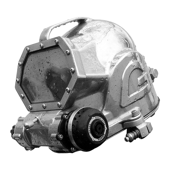
GX300 REGULATOR
FOR THE
AQUA LUNG G3000SS DIVING HELMET
MAINTENANCE MANUAL
FOR
AUTHORISED TECHNICIANS
Issue 4
Document No. AP2548
28/08/2015
APEKS MARINE EQUIPMENT LTD, NEPTUNE WAY, BLACKBURN, LANCASHIRE. BB1 2BT
Tel: +44 (0) 1254 692200 Fax: +44 (0) 1254 692211 E-mail: info@apeks.co.uk Web: www.apeks.co.uk
Advertisement

Subscribe to Our Youtube Channel
Related Manuals for Apeks GX300


Summary of Contents for Apeks GX300
- Page 1 FOR THE AQUA LUNG G3000SS DIVING HELMET MAINTENANCE MANUAL AUTHORISED TECHNICIANS Issue 4 Document No. AP2548 28/08/2015 APEKS MARINE EQUIPMENT LTD, NEPTUNE WAY, BLACKBURN, LANCASHIRE. BB1 2BT Tel: +44 (0) 1254 692200 Fax: +44 (0) 1254 692211 E-mail: info@apeks.co.uk Web: www.apeks.co.uk...
-
Page 2: Amendments Record
Amendments and approval of this document can only be carried out by the relevant people listed on the Approved list of signatures, which is listed in the Apeks Quality Manual. To instigate a change, a Task / Change request form, (Form No. -
Page 3: Copyright Notice
Apeks or Aqualung to speak directly with cleaning procedure. a Technical Advisor before proceeding any further. - Page 4 Remove O ring (6) from valve diaphragm housing (7) using O ring removal tool AT79 Unscrew the 4 mouthpiece screws (5) using the 5/64” allen key. Disassembly of the GX300 Regulator Case is Now Complete...
- Page 5 GX300 Regulator Maintenance Manual Disassembly Procedures for the Valve Using the protruding arms of the spindle locking washer (22) pull the whole side valve shuttle assembly from the Spindle Assembly side valve spindle (15). Remove Nylock nut (27) using 7mm nut driver or spanner and put to one side.
- Page 6 GX300 Regulator Maintenance Manual Unscrew nyloc nut (27) and dispose of, then slide the Remove O ring (18) spindle bush (23) and spindle locking washer (22) free from valve shuttle (17). from the side valve shuttle (17). Remove silicone seat (16) from valve shuttle (17).
- Page 7 GX300 Regulator Maintenance Manual Disassembly Procedures for the Valve Push on the underside of the diaphragm ring (32) to reveal the diaphragm (30). Peel the diaphragm Diaphragm (30) at one edge to reveal the groove which it was seated in and work free all the way around until the diaphragm ring (32) is free.
- Page 8 GX300 Regulator Maintenance Manual Carefully push on retaining ring (35) to diaphragm Assembly Procedures for the Valve (30). Ensure the eight teeth on the retaining ring Diaphragm Assembly (35) are facing towards the diaphragm (30). They must also fit between the four stop lugs of the diaphragm (30) but not go past or over them.
- Page 9 GX300 Regulator Maintenance Manual NOTE: Lubricate valve shuttle (17) shaft only. Do not Assembly Procedures for the GX300 lubricate threads or silicone valve seat end. Inlet Valve Place the silicone valve seat (16) on a clean flat surface face down. Press the valve shuttle (17) onto the seal until its fully located into place.
- Page 10 The ‘7 hole’ setting is the optimum setting for normal a preliminary setting diving operations. For further adjustment see page 11. only Fit O ring (12) onto Assembly of the GX300 Inlet Valve is Now spindle bush (23). Complete Assembly Procedures for the GX300 Regulator Case...
- Page 11 Assembly of the GX300 Regulator Case Regulator Adjustment is Now Complete is Now Complete See Page 12 for Optional Magnehelic Regulator Adjustment is Now Required...
- Page 12 10) is the optimum setting for normal diving operations. button to ensure all At this setting the regulator will function correctly within parts are operational a wide range of regulated supply pressures (see GX300 and have free Regulated Supply Pressure Guidelines on page 15). movement.
- Page 13 5. Fit the 3 new cap head screws (10), tighten each screw using a 5/32” allen key to 5Nm (44 in.lb). Final Installation of the GX300 Regulator is Now Complete Caution: Do not overtighten as this may damage the cover...
- Page 14 NOTE: When retro fitting the new GX300 regulator to an existing G2000SS helmet it will then be known as the Aqualung G3000SS helmet. A double exhaust kit (water dump), PN 400111, should be fitted to the helmet at the same time.
- Page 15 Apeks Quick Disconnect Hose -AP0205/Y, into the second port of the G3000SS Helmet d. Apeks Switch Block - AP0281/G, connected to the other end of the QD hose via the bail out port e. One of Apeks First Stage Regulators: i.
- Page 16 Main surface MP gas supply, using surface gas control panel and standard diver’s umbilical, connected directly into one port of the G3000SS Helmet c. Apeks Quick Disconnect Hose -AP0205/Y, from the first stage regulator to the second port of the G3000SS Helmet d. One of Apeks First Stage Regulators: i.
- Page 17 GX300 Regulator Maintenance Manual Table 1 - Troubleshooting Guide SYMPTOM POSSIBLE CAUSE TREATMENT Leakage from 1. Excessively high supply pressure. 1. Ensure supply pressure is below the regulator maximum stated within the pressure exhaust ports. guidelines. 2. Supply pressure is above the standard 2.
- Page 18 GX300 Regulator Maintenance Manual SYMPTON POSSIBLE CAUSE TREATMENT Excessive 1. Low supply pressure. 1. Check equipment upstream. work of 2. Lever (25) set too low. 2. Adjust lever. breathing. 3. Interruption in supply to the 3. Check for leaks. Check the supply hoses are regulator.
- Page 19 GX300 Regulator Maintenance Manual Table 2 - Recommended Tool List PART NO. DESCRIPTION APPLICATION AT33 3/4” Spanner Side Valve Lock Nut (1) AT51/L Slotted Valve adjustment Tool Valve Seat (13) AT88 Seal Expander O Ring (18+19) AT79 O Ring Tool...
- Page 20 GX300 Regulator Maintenance Manual Cleaning and Lubrication Procedure Cleaning Brass and Stainless Steel Parts If required, pre-clean in warm, soapy water* using a nylon bristle tooth brush. Thoroughly clean parts in an ultrasonic cleaner filled with a solution of household white distilled vinegar (Acetic Acid) mixed with fresh water (max 50% vinegar).
- Page 21 GX300 Regulator Maintenance Manual Table 3 - Recommended Lubricants & Cleaners LUBRICANT / CLEANER APPLICATION SOURCE Christo-Lube MCG-111 All O ring seals Lubrication Technologies ® (Lubricant). 310 Morton Street Jackson, OH 45640, USA (800) 477-8704, or Apeks Marine Equipment Ltd...
- Page 22 GX300 Regulator Maintenance Manual Table 4 - Torque Specifications PART NUMBER DESCRIPTION / KEY NUMBER TORQUE AP2502 Lock Nut 5 Nm (44 in.lb) A2 Stainless Steel Socket Head Cap Screw UNC AP2512 5 Nm (44 in.lb) 12-24 x 0.375 A2 Stainless Steel Socket Countersunk Screw UNC AP2510 0.5 Nm (4 in.lb)
-
Page 23: Exploded Parts Diagram
GX300 Regulator Maintenance Manual AP0300 GX300 Regulator Exploded Parts Diagram AP2502 Valve Lock Nut AP2501 Valve Diaphragm Housing AP2500 Valve Case AP2505 Diaphragm Spring AP2509 BS029 O ring AP2506 Spring Carrier AP2503 Valve Mouthpiece AP2512 A2 Stainless Steel Socket Head Cap Screw UNC 12-24 x 0.375... - Page 24 GX300 Regulator Maintenance Manual AP0279 Valve Spindle Assembly Exploded Parts Diagram AP2021 Spring AP1154 BS010 O ring AP2033 Valve Seat AP2515 Valve Sleeve AP2516 Spindle Locking Washer AP1159 BS014 O ring AP2513 Valve Spindle AP2518 Spindle Bush 129638 Silicone Seat...
- Page 25 GX300 Regulator Maintenance Manual AP0278 Valve Diaphragm Assembly Exploded Parts Diagram AP2525 BS0660-20 O ring AP2551 Diaphragm Ring AP2526 Diaphragm Carrier AP2550 Exhalation Diaphragm AP2553 Diaphragm 336100005 Sealing Disc (qty 5) (individual part no. 460190393) AP2528 Diaphragm Pad 336100008 Securing Ring (qty10) (individual part no.
-
Page 26: Technical Support
TECHNICAL SUPPORT GX300 REGULATOR MAINTENANCE MANUAL AUTHORISED TECHNICIANS Apeks Marine Equipment Ltd Neptune Way, Blackburn, Lancashire, England, BB1 2BT Tel: 0044 (0) 1254 692200...
Need help?
Do you have a question about the GX300 and is the answer not in the manual?
Questions and answers