
Related Manuals for Armstrong AVF


Summary of Contents for Armstrong AVF
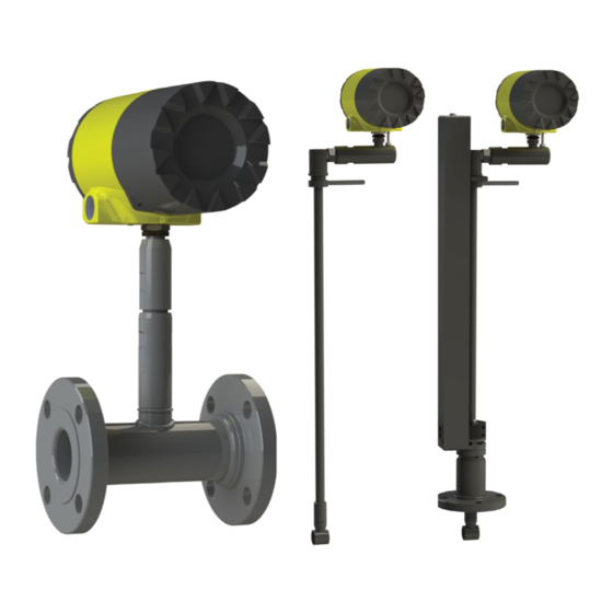
- Page 1 Armstrong AVF and AVI Vortex Meter Installation and Operation Manual Please read and save these instructions. 359-EN V1.0...
- Page 2 Some models can only be properly cleaned during the manufacturing process. Armstrong International is not liable for any damage or personal injury, whatsoever, resulting from the use of Armstrong’s standard vortex meters for oxygen gas.
-
Page 3: Table Of Contents
Table of Contents Chapter 1 Introduction Chapter 2 Installation AVF and AVI Vortex Mass Flow Meters ......7 Installation Overview ............. 14 Using this Manual ............7 Flow Meter Installation Requirements ......14 Note and Safety Information ......... 8 Unobstructed Flow Requirements ......... 15 Receipt of System Components ........ - Page 4 Symptom: Meter Displays Pressure Fault ........... 110 Electronics Assembly Replacement ............111 Pressure Sensor Replacement (Series AVF Only) ........112 Returning Equipment to the Factory ............112 Designs, materials, weights and performance ratings are approximate and subject to change without notice. Visit armstronginternational.com for up-to-date information.
- Page 5 Table of Contents Appendix A Product Specifications Appendix B Approvals Appendix C Flow Meter Calculations Appendix D Glossary Figures Figures continued 1-1. In-Line Vortex Multi-Parameter Mass Flow Meter ....9 2-42 High Power Flow Meter Junction Box ......... 45 1-2. Measurement Principle of Vortex Flow Meters ......9 2-43.
- Page 6 Caution! Calibration must be performed by qualified personnel. Armstrong International strongly recommends that you return your flow meter to the factory for calibration. In order to achieve accurate and repeatable performance, the flow meter must be installed with the specified minimum length of straight pipe upstream and downstream of the flow meter’s sensor head.
-
Page 7: Chapter 1 Introduction
Using This Manual This manual provides information needed to install and operate both the AVF In-Line and AVI Insertion Flow Meters. • Chapter 1 includes the introduction and product description • Chapter 2 provides information needed for installation •... -
Page 8: Note And Safety Information
Receipt of System Components When receiving an Armstrong mass flow meter, carefully check the outside packing carton for damage incurred in shipment. If the carton is damaged, notify the local carrier and submit a report to the factory or distributor. Remove the packing slip and check that all ordered components are present. -
Page 9: Velocity Measurement
Close to the shedder bar, the distance (or wave length) between vortices is always constant and measurable. Therefore, the volume encompassed by each vortex remains constant, as shown below. By sensing the number of vortices passing by the velocity sensor, the AVF or AVI flow meter computes the total fluid volume. -
Page 10: Vortex Frequency Sensing
How the Vortex Mass Flow Meter Operates Vortex Frequency Sensing The velocity sensor incorporates a piezoelectric element that senses the vortex frequency. This element detects the alternating lift forces produced by the Von Karman vortices flowing downstream of the vortex shedder bar. The alternating electric charge generated by the piezoelectric element is processed by the transmitter’s electronic circuit to obtain the vortex shedding frequency. -
Page 11: Pressure Drop
Figure 1-3. Reynolds Number Range for the AVF and AVI vortex meters Pressure Drop The pressure drop for series AVI insertion meters is negligible. The pressure drop for series AVF in-line meters is defined ∆P = .00024 PI V English units ( ∆P in psi, PI in lb/ft , V in ft/sec) ∆P = .000011 PI V... -
Page 12: Minimum Back Pressure
∆P = Permanent pressure loss across the flow meter (psia or bara). = Liquid vapor pressure at actual flowing conditions (psia or bara). Temperature Measurement Armstrong vortex flow meters use a 1000 ohm platinum resistance temperature detector (PRTD) to measure fluid temperature. Pressure Measurement Armstrong vortex flow meters incorporate a solid-state pressure transducer isolated by a 316 stainless steel diaphragm. -
Page 13: Multivariable Options
V4, external pressure transmitter input. Line Size / Process Connections / Materials The AVF In-line model is built for line sizes ½ through 4 inch wafer or ½ through 8 inch flanged design using ANSI 150, 300, 600, PN16, 40, or 64 class flanges. -
Page 14: Installation Overview
AVI Insertion type flow meter installations are covered in this chapter. After reviewing the installation requirements given below, see page 16 for Series AVF installation instructions. See page 19 for Series AVI installation instructions. Wiring instructions begin on page 32. -
Page 15: Unobstructed Flow Requirements
10 D D = Internal diameter of channel. N/A = Not applicable Figure 2-1. Recommended Pipe Length Requirements for Installation, Series AVF/AVI Designs, materials, weights and performance ratings are approximate and subject to change without notice. Visit armstronginternational.com for up-to-date information. - Page 16 Installation Overview – continued Recommended Meter Locations Liquid Horizontal Liquid Vertical Gas or Steam Horizontal Gas or Steam Vertical Designs, materials, weights and performance ratings are approximate and subject to change without notice. Visit armstronginternational.com for up-to-date information.
- Page 17 AVF In-Line Flow Meter Installation Install the AVF In-Line Flow Meter between two conventional pipe flanges as shown in Figures 2-3 and 2-4. The meter inside diameter is equal to the same size nominal pipe ID in schedule 80. For example, a 2” meter has an ID of 1.939”...
-
Page 18: Wafer-Style Flow Meter Installation
Installation Overview – continued Wafer-Style Flow Meter Installation Install the wafer-style meter between two conventional pipe flanges of the same nominal size as the flow meter. If the process fluid is a liquid, make sure the meter is located where the pipe is always full. This may require locating the meter at a low point in the piping system. -
Page 19: Flange-Style Flow Meter Installation
Installation Overview – continued Flange-Style Flow Meter Installation Install the flange-style meter between two conventional pipe flanges of the same nominal size as the flow meter. If the process fluid is a liquid, make sure the meter is located where the pipe is always full. This may require locating the meter at a low point in the piping sys-tem. - Page 20 Installation Overview – continued AVI Insertion Flow Meter Installation Prepare the pipeline for installation using either a cold tap or hot tap method described on the following pages. Refer to a standard code for all pipe tapping operations. The following tapping instructions are general in nature and intended for guideline purposes only.
-
Page 21: Cold Tap Guidelines
Installation Overview – continued Cold Tap Guidelines Refer to a standard code for all pipe tapping operations. The following tapping instructions are general in nature and intended for guideline purposes only. 1. Turn off the flow of process gas, liquid or steam. Verify that the line is not pressurized. 2. -
Page 22: Hot Tap Guidelines
Installation Overview – continued Hot Tap Guidelines Refer to a standard code for all pipe tapping operations. The following tapping instructions are general in nature and intended for guideline purposes only. 1. Confirm that the installation site meets the minimum upstream and downstream pipe diameter requirements. 2. -
Page 23: Flow Meter Insertion
Installation Overview – continued Flow Meter Insertion The sensor head must be properly positioned in the pipe. For this reason, it is important that insertion length calculations are carefully followed. A sensor probe inserted at the wrong depth in the pipe will result in inaccurate readings. -
Page 24: Installing Meters With A Compression Connection
Installation Overview – continued Installing Flow Meters with a Compression Connection* Use the following formula to determine insertion length for flow meters (NPT and flanged) with a compression process connection. The installation procedure is given on the next page. Insertion Length Formula I = S –... - Page 25 Installation Overview – continued Insertion Procedure for Meters with a Compression Connection Sensor alignment pointer Enclosure adapter Stem Compression nut Stem housing Compression nut Stem housing Sensor head 2-inch NPT Flange connection connection Figure 2-7. Flow Meter with Compression Type Fitting 1.
-
Page 26: Installing Meters With A Packing Gland Connection
Installation Overview – continued Installing Flow Meters with a Packing Gland Connection* Use the formula below to determine the insertion depth for flow me-ters (NPT and flanged) equipped with an insertion tool. To install, see the next page for instructions for meters with a permanent insertion tool. For meters with a removable insertion tool, see page 27. - Page 27 Installation Overview – continued Insertion Procedure for Flow Meters with Permanent Insertion Tool Depth marker arrow Upper retractor bracket Stanchion Stem lock bolt (center) Sensor alignment pointer Scribe mark Stem Packing gland nut Stem housing Permanent insertion tool Sensor head Figure 2-9.
- Page 28 Installation Overview – continued Insertion Procedure for Flow Meters with Removable Insertion Tool Depth marker arrow Upper retractor bracket Stanchion Stem lock bolt (center) Sensor alignment pointer Scribe mark Stem Stem clamp nuts Stem clamp bolts Packing gland nut (covered by stem clamp) Permanent insertion tool Lower retractor bracket Stem housing...
-
Page 29: Insertion Calculation (Meters Without Insertion Tool)
Installation Overview – continued Installation of Meters with Packing Gland Connection (No Insertion Tool)* Use the following formula to determine insertion depth for meters with a packing gland connection (NPT and flanged) without an inser-tion tool. Insertion Length Formula I = S – F – R – t Where: I = Insertion length. - Page 30 Installation Overview – continued Insertion Procedure for Flow Meters with No Insertion Tool (Packing Gland Connection) 1. Calculate the required sensor probe insertion length. 2. Fully retract the stem until the sensor head is touching the bottom of the stem housing. Remove the two top stem clamp nuts and loosen two stem clamp bolts.
-
Page 31: Adjusting Meter Orientation
The first ro-tates the position of the LCD display/keypad and is available on both in-line and insertion meters. The second is to rotate the enclosure po-sition. This adjustment is only allowed on AVF In-Line meters. Rotate display/keypad in 90 degree increments (maximum 180 degrees from original position) Figure 2-12. -
Page 32: Enclosure Adjustment
Installation Overview – continued Enclosure Adjustment (AVF Only) Loosen locking nut and rotate enclosure (maximum 180 degrees from original position Figure 2-13. Enclosure Viewing Adjustment To avoid damage to the sensor wires, do not rotate the enclosure beyond 180-degrees from the original position. -
Page 33: Loop Power Flow Meter Wiring Connections
Loop Power Flow Meter Wiring Connections The NEMA 4X enclosure contains an integral wiring compartment with one dual strip terminal block (located in the smaller end of the enclosure). Two 3/4-inch female NPT conduit entries are available for separate power and signal wiring. -
Page 34: Input Power Connections
Installation Overview – continued Input Power Connections To access the wiring terminal blocks, locate and loosen the small set screw which locks the small enclosure cover in place. Unscrew the cover to expose the terminal block. DC Power Wiring Connect 4-20 mA loop power (12 to 36 VDC at 25 mA, 1W max.) to the +Loop Power and –Loop Power terminals on the terminal block. -
Page 35: 4-20 Ma Output Connections
4-20 mA Output Connections The AVF/AVI meters have a single 4-20 mA loop. The 4-20 mA loop current is controlled by the meter electronics. The electronics must be wired in series with the sense resistor or current meter. The current control electronics require 12 volts at the input terminals to operate correctly. -
Page 36: Pulse Output Connections
Installation Overview – continued Pulse Output Connections The pulse output is used for a remote counter. When the preset volume or mass (defined in the totalizer settings, see page 3-10) has passed the meter, the output provides a 50 millisecond square pulse. The pulse output requires a separate 5 to 36 VDC power supply. -
Page 37: Frequency Output Connections
Installation Overview – continued Frequency Output Connections The frequency output is used for a remote counter. It can be scaled to output a 1 to 10 kHz signal proportional to mass or volume flow, temperature, pressure or density. The frequency output requires a separate 5 to 36 VDC power supply. The frequency output optical relay is a normally- open single-pole re-lay. -
Page 38: Remote Electronics Wiring
Installation Overview – continued Remote Electronics Wiring The remote electronics enclosure should be mounted in a convenient, easy to reach location. For hazardous location installations, make sure to observe agency requirements for installation. Allow some slack in the interface cable between the junction box and the remote electron-ics enclosure. - Page 39 Installation Overview – continued Figure 2-23. Loop Power Volumetric Flowmeter Junction Box Sensor Con-nections Supplied Prior to Jan. 1, 2014 (Wires enter the flow connector from the right side of the connector shown above.) Figure 2-24. Loop Power Mass Flowmeter Junction Box Sensor Connections Designs, materials, weights and performance ratings are approximate and subject to change without notice.
-
Page 40: High Power Flow Meter Wiring Connections
Installation Overview – continued High Power Meter Wiring Connections The NEMA 4X enclosure contains an integral wiring compartment with one dual strip terminal block (located in the smaller end of the enclosure). Two 3/4-inch female NPT conduit entries are available for separate power and signal wiring. - Page 41 Installation Overview – continued Figure 2-26. AC Power Connections Caution! The AC wire insulation temperature rat-ing must meet or exceed 90°C (194°F), maximum operating voltage 600 VRMS. Figure 2-27. DC Wiring Terminals Designs, materials, weights and performance ratings are approximate and subject to change without notice. Visit armstronginternational.com for up-to-date information.
-
Page 42: Dc Power Connections
Installation Overview – continued DC Power Wiring The DC power wire size must be 20 to 12 AWG with the wire stripped 1/4 inch (7 mm). Connect 18 to 36 VDC (300 mA, 9 W max-imum) to the +DC Pwr and –DC Pwr terminals on the terminal block. Torque all connections to 4.43 to 5.31 in-lbs (0.5 to 0.6 Nm). -
Page 43: 4-20 Ma Output Connections
4-20 mA Output Connections The standard AVF and AVI Flow Meters have a single 4-20 mA loop. Two additional loops are available on the op-tional communication board. The 4-20 mA loop current is controlled by the meter electronics. The electronics must be wired in series with the sense resistor or current meter. -
Page 44: Frequency Output Connections
Installation Overview – continued Figure 2-31. Non-Isolated 4–20 mA Output Using Meter Input Power Supply Figure 2-32. Isolated 4–20 mA Output Using Meter Provided Power Supply Frequency Output Connections The frequency output is used for a remote counter. It can be scaled to output a 1 to 10 kHz signal proportional to mass or volume flow, temperature, pressure or density. -
Page 45: Pulse Output Connections
Installation Overview – continued Figure 2-34. Non-Isolated Frequency Output Using Input Power Supply Figure 2-35. Isolated Frequency Output Using Meter Provided Power Supply Pulse Output Connections The pulse output is used for a remote counter. When the preset vol-ume or mass (defined in the totalizer settings, see page 3-10) has passed the meter, the output provides a 50 millisecond square pulse. -
Page 46: Isolated Pulse Output Using External Power Supply
Installation Overview – continued Figure 2-36. Isolated Pulse Output Using External Power Supply Figure 2-37. Non-Isolated Pulse Output Using Input Power Supply Figure 2-38. Isolated Pulse Output Using Meter Provided Power Supply Designs, materials, weights and performance ratings are approximate and subject to change without notice. Visit armstronginternational.com for up-to-date information. -
Page 47: Alarm Output Connections
Installation Overview – continued Alarm Output Connections One alarm output (Alarm 1) is included on the standard Pro-V™ Flow Meter. Two or more alarms (Alarm 2 and Alarm 3) are included on the optional communication board. The alarm output requires a sepa-rate 5 to 36 VDC power supply. The alarm output optical relay is a normally-open single-pole relay. -
Page 48: Remote Electronics Wiring
Installation Overview – continued Figure 2-41. Isolated Alarm Output Using Meter Provided Power Supply Remote Electronics Wiring The remote electronics enclosure should be mounted in a convenient, easy to reach location. For hazardous location installations, make sure to observe agency requirements for installation. Allow some slack in the interface cable between the junction box and the remote electron-ics enclosure. -
Page 49: Optional Input Electronics Wiring
Installation Overview – continued Optional Input Electronics Wiring The meter has two optional input wiring terminals, maximum wire size is 16 AWG. These can be used to input a Remote or Second RTD input in the case of an Energy Monitoring meter, for the input of a Remote Pressure Transducer, to pass a Contact Closure or for a Remote Density measurement to name a few. -
Page 50: Optional External 4-20 Ma Input Wiring
Installation Overview – continued Optional External 4-20 mA Input Wiring The meter is set to have Option 1 used for the external input. Pro-gramming menus that pertain to the optional 4-20 mA input are locat-ed in the Hidden Diagnostics Menu in Chapter 5. Figure 2-44. -
Page 51: Optional Contact Closure Input Wiring
Installation Overview – continued Figure 2-46. External 4-20 mA Input Wiring - AC Powered Meter Follow the above diagram to wire the external 4-20 mA input into the flow meter using power from the 24 VDC output of an AC powered meter. Optional Contact Closure Input Wiring Figure 2-47. -
Page 52: Chapter 3 Operating Instructions
Chapter 3 – Operating Instructions After installing the AVF or AVI Flow Meter, you are ready to begin operation. The sections in this chapter explain the display/keypad commands, meter start-up and programming. The meter is ready to operate at start up without any special programming. -
Page 53: Start Up
Operating Instructions – continued Start-Up To begin flow meter operation: 1. Verify the flow meter is installed and wired as described in Chapter 2. 2. Apply power to the meter. At start up, the unit runs a series of self-tests that check the RAM, ROM, EPROM and all flow sensing components. -
Page 54: Using The Setup Menus
Operating Instructions – continued Using the Setup Menus Designs, materials, weights and performance ratings are approximate and subject to change without notice. Visit armstronginternational.com for up-to-date information. -
Page 55: Programming The Flow Meter
ENTER to continue. 3. Use the Setup Menus described on the following pages to customize the multiparameter features of your AVF/AVI Flow Meter. (The entire lower display line is available for entering parameters.) Some items depicted in the graphic on the preceding page may not be displayed based on flow meter configuration settings 4. -
Page 56: Output Menu
Operating Instructions – continued Output Menu Designs, materials, weights and performance ratings are approximate and subject to change without notice. Visit armstronginternational.com for up-to-date information. - Page 57 Operating Instructions – continued Example for Setting an Output The following shows how to set Output 1 to measure mass flow with 4 mA = 0 lb/hr and 20 mA = 100 lb/hr with a time constant of 5 seconds. (All outputs are disabled while using the Setup Menus.) First, set the desired units of measurement: 1.
-
Page 58: Display Menu
Operating Instructions – continued Display Menu Use the Display Menu to set the cycle time for automatic screen sequencing used in the Run Mode, change the precision of displayed values, smooth the values or enable or disable each item displayed in the Run Mode screens. Example for Changing a Run Mode Display Item The following shows how to remove the temperature screen from the Run Mode screens. -
Page 59: Alarms Menu
Operating Instructions – continued Alarms Menu Example for Setting an Alarm The following shows how to set Relay Alarm 1 to activate if the mass flow rate is greater than 100 lb/hr. You can check the alarm configuration in the Run Mode by pressing the keys until Alarm [1] appears. The lower line displays the mass flow rate at which the alarm activates. -
Page 60: Totalizer #1 Menu
Operating Instructions – continued Totalizer #1 Menu Use the Totalizer Menu to configure and monitor the totalizer. The totalizer output is a 50 millisecond (.05 second) positive pulse (relay closed for 50 milliseconds). The totalizer cannot operate faster than one pulse every 100 millisecond (.1 second). -
Page 61: Totalizer #2 Menu
Operating Instructions – continued Totalizer #2 Menu Use the Totalizer #2 to Monitor Flow or Energy. Note that Totalizer #2 does not operate a relay, it is for monitoring only. Designs, materials, weights and performance ratings are approximate and subject to change without notice. Visit armstronginternational.com for up-to-date information. -
Page 62: Energy Menu
Operating Instructions – continued Energy Menu – For EMS Energy Meters Only Configuration: There are several possibilities regarding the measurement of water or steam energy given the location of the meter and the use of a second RTD. The table below summarizes the possibilities: Fluid Meter Location Second RTD... -
Page 63: Fluid Menu
Operating Instructions – continued Fluid Menu Use the Fluid Menu to configure the flow meter for use with common gases, liquids and steam. Your flow meter is pre- programmed at the factory for your application’s process fluid. Reference Richard W. Miller, Flow Measurement Engineering Handbook (Third Edition, 1996), page 2-75 for definition and use of the Goyal-Doraiswamy equation and page 2-76 for the definition and use of the API 2540 equation. -
Page 64: Units Menu
Operating Instructions – continued Units Menu Use the Units Menu to configure the flow meter with the desired units of measurement. (These are global settings and determine what appears on all screens.) Designs, materials, weights and performance ratings are approximate and subject to change without notice. Visit armstronginternational.com for up-to-date information. -
Page 65: Time And Date Menu
Operating Instructions – continued Time & Date Menu Use the Time and Date Menu to enter the correct time and date into the flow meter’s memory. The parameters are used in the Run Mode and the alarm and system log files. Note: Time is displayed in AM/PM format, but military format is used to set the time. -
Page 66: Diagnostics Menu
Operating Instructions – continued Diagnostics Menu Use the Diagnostics Menu to simulate operation and review the system files. The system log files contain time/date stamped messages including: power on, power off, programming time outs, parameter faults, incorrect password entry and other various information relative to system operation and programming. The simulated inputs are for testing the meter to verify that the programming is correct. -
Page 67: Calibration Menu
Operating Instructions – continued Calibration Menu The Calibration Menu contains the calibration coefficients for the flow meter. These values should by changed only by properly trained personnel. The Vortex Coef Ck and Low Flow Cutoff are set at the factory. Consult the factory for help with these settings if the meter is showing erratic flow rate. -
Page 68: Password Menu
Operating Instructions – continued Password Menu Use the Password Menu to set or change the system password. The factory-set password is 1234. Designs, materials, weights and performance ratings are approximate and subject to change without notice. Visit armstronginternational.com for up-to-date information. -
Page 69: Chapter 4 Serial Communications
Chapter 4 – Serial Communications HART Communications ® The HART Communications Protocol (Highway Addressable Remote Transducer Protocol) is a bidirectional digital serial communications protocol. The HART signal is based on the Bell 202 standard and is superimposed on 4-20 mA Output 1. -
Page 70: Dc Powered Meter Wiring (Hart)
Serial Communications – continued DC Powered Meter Wiring Figure 4-2.DC Powered Meter Wiring (HART) AC Powered Meter Wiring Figure 4-3.AC Powered Meter Wiring (HART) Designs, materials, weights and performance ratings are approximate and subject to change without notice. Visit armstronginternational.com for up-to-date information. - Page 71 Serial Communications – continued HART Commands with the Digital Display Menu ® Online Menu Designs, materials, weights and performance ratings are approximate and subject to change without notice. Visit armstronginternational.com for up-to-date information.
- Page 72 Serial Communications – continued HART Commands with the Digital Display Menu – continued ® Analog Output Menu Designs, materials, weights and performance ratings are approximate and subject to change without notice. Visit armstronginternational.com for up-to-date information.
- Page 73 Serial Communications – continued HART Commands with the Digital Display Menu – continued ® Fluid Menu Designs, materials, weights and performance ratings are approximate and subject to change without notice. Visit armstronginternational.com for up-to-date information.
- Page 74 Serial Communications – continued HART Commands with the Digital Display Menu – continued ® Diagnostics Menu Review Menu Designs, materials, weights and performance ratings are approximate and subject to change without notice. Visit armstronginternational.com for up-to-date information.
- Page 75 Serial Communications – continued HART Commands with the Digital Display Menu – continued ® Sensor Cal Menu Designs, materials, weights and performance ratings are approximate and subject to change without notice. Visit armstronginternational.com for up-to-date information.
- Page 76 Serial Communications – continued HART Commands with Generic Digital Display Menu ® Use password 16363. Designs, materials, weights and performance ratings are approximate and subject to change without notice. Visit armstronginternational.com for up-to-date information.
- Page 77 Serial Communications – continued Fast Key Sequence Use password 16363. Continued on next page Designs, materials, weights and performance ratings are approximate and subject to change without notice. Visit armstronginternational.com for up-to-date information.
- Page 78 Serial Communications – continued Fast Key Sequence – continued Designs, materials, weights and performance ratings are approximate and subject to change without notice. Visit armstronginternational.com for up-to-date information.
-
Page 79: Modbus Communications
Serial Communications – continued Modbus Communications Applicable Flow Meter Models Armstrong Vortex Flow Meters, Models AVF and AVI with Modbus communication protocol and firmware version 4.00.58 and above. Overview This document describes the preliminary implementation of the Modbus communication protocol for use in monitoring common process variables in the Armstrong Vortex Flow Meter. -
Page 80: Menu Items
Serial Communications – continued Menu Items The following menu items are in the Output Menu and allow selection and control of the Modbus communication protocol. Address When the Modbus protocol is selected, the Modbus address is equal to the user programmable device address if it is in the range 1…247, in accordance with the Modbus specification. - Page 81 Serial Communications – continued Modbus Protocol The Modbus RTU protocol is supported in this implementation. Supported baud rates are 1200, 2400, 4800, 9600, 19200, 38400, 57600, and 115200. The default baud rate is 19200 baud. Depending upon the Modbus protocol selected, data are transmitted in 8-bit data frames with even or odd parity and 1 stop bit, or no parity and 2 or 1 (non-standard) stop bits.
-
Page 82: Register Definitions
Serial Communications – continued Register Definitions The meter serial number and those variables that are commonly monitored (mass, volume and energy flow rates, total, pressure, temperature, density, viscosity, Reynolds number, and diagnostic variables such as frequency, velocity, gain, amplitude and filter setting) are accessible via the Modbus protocol. Long integer and floating point numbers are accessed as pairs of 16-bit registers in the register order selected in the Modbus Order menu. - Page 83 Serial Communications – continued Table 4-2.Register Definitions Function codes 03 (read holding registers) and 04 (read input registers) are the only codes supported for reading these registers, and function codes for writing holding registers are not implemented. We recommend that the floating point and long integer registers be read in a single operation with the number of registers being a multiple of two.
- Page 84 Serial Communications – continued Exception Status Definitions The Read Exception Status command (function code 07) returns the exception status byte, which is defined as follows. This byte may be cleared by setting “coil” register #00008 (function code 5, address 7, data = 0xff00). Bit(s) Definition Byte order (see Modbus Order on page 2)
- Page 85 Serial Communications – continued Control Register Definitions The only writeable registers in this implementation are the Reset Exception Status, Reset Meter and Reset Totalizer functions, which are implemented as ”coils” which may be written with the Write Single Coil command (function code 05) to address 7 through 9, respectively, (register #00008 through #00010).
- Page 86 Serial Communications – continued Exception Response Message Format Examples Read the exception status byte from the device with address 1: 01 07 41 E2 01 Device address 07 Function code, 07 = read exception status 41 E2 CRC A typical response from the device is as follows: 01 07 03 62 31 01 Device address 07 Function code...
- Page 87 Serial Communications – continued Examples – continued An attempt to read register(s) that don’t exist 01 04 00 00 00 50 F1 D2 Device address 04 Function code 4 = read input register 00 00 Starting address 00 50 Number of registers = 80 F0 36 CRC results in an error response as follows: 01 Device address...
- Page 88 Serial Communications – continued Examples – continued The unit responds with an identical message to that transmitted, and the totalizer is reset. If the “coil” is turned off as in the following message, the response is also identical to the transmitted message, but the totalizer is not affected. 01 05 00 09 00 00 1D C8 01 Device address 05 Function code 5 = write single coil...
-
Page 89: Bacnet™ Mstp Communications
MS/TP bus communicate at the same baud rate. The baud rate setting determines the rate at which devices communicate data over the bus. The baud rate settings available on Armstrong Vortex Flow Meters are 9600, 19200 and 38400. -
Page 90: Supported Bacnet Objects
Serial Communications – continued 3. Supported BACnet Objects A BACnet object represents physical or virtual equipment information, as a digital input or parameters. Armstrong Vortex Flow Meters presents the following object types: a. Device Object b. Analog Input c. Binary Input d. - Page 91 Serial Communications – continued (W) – Writable Property. 3.1. Device Object: The Device object default property values are as follows – Designs, materials, weights and performance ratings are approximate and subject to change without notice. Visit armstronginternational.com for up-to-date information.
- Page 92 Serial Communications – continued Note - Device Communication Control: Password – “armstrong” 3.2. Analog Input Object: Vortex Mass Flow Meters Analog Input type objects are described in the below Table – Designs, materials, weights and performance ratings are approximate and subject to change without notice. Visit armstronginternational.com for up-to-date information.
- Page 93 Serial Communications – continued Designs, materials, weights and performance ratings are approximate and subject to change without notice. Visit armstronginternational.com for up-to-date information.
- Page 94 Serial Communications – continued Designs, materials, weights and performance ratings are approximate and subject to change without notice. Visit armstronginternational.com for up-to-date information.
- Page 95 Serial Communications – continued 3.3. Binary Input Object: Vortex Mass Flow Meters Binary Input type objects are described in the below Table. Note - Binary Input 4, Present value always read zero, because no information available from client, so the polarity property doesn’t impact on Present value property when the Out of service property is false.
-
Page 96: Annex - Bacnet Protocol Implementation Conformance Statement
Serial Communications – continued 4. ANNEX - BACnet Protocol Implementation Conformance Statement Date: 19-April-2012 Vendor Name: Armstrong International Product Name: AVF/AVI Vortex Flow Meter Product Model Number: AVF/AVI V2/V3 Applications Software Version: 1.07 Firmware Revision: N/A BACnet Protocol Revision: 4... - Page 97 Serial Communications – continued Segmentation Capability: Able to transmit segmented messages Window Size Able to receive segmented messages Window Size Designs, materials, weights and performance ratings are approximate and subject to change without notice. Visit armstronginternational.com for up-to-date information.
- Page 98 Serial Communications – continued Standard Object Types Supported: Designs, materials, weights and performance ratings are approximate and subject to change without notice. Visit armstronginternational.com for up-to-date information.
- Page 99 Serial Communications – continued Object List: Designs, materials, weights and performance ratings are approximate and subject to change without notice. Visit armstronginternational.com for up-to-date information.
- Page 100 Serial Communications – continued Data Link Layer Options: BACnet IP, (Annex J) BACnet IP, (Annex J), Foreign Device ISO 8802-3, Ethernet (Clause 7) ANSI/ATA 878.1, 2.5 Mb. ARCNET (Clause 8) ANSI/ATA 878.1, EIA-485 ARCNET (Clause 8), baud rate(s) ...
- Page 101 Serial Communications – continued Network Security Options: Non-secure Device - is capable of operating without BACnet Network Security Secure Device - is capable of using BACnet Network Security (NS-SD BVBB) Multiple Application-Specific Keys: Supports encryption (NS-ED BVBB) ...
-
Page 102: Acronyms And Definitions
Serial Communications – continued 5. Acronyms and Definitions Item Description APDU Application Protocol Data Unit BACnet Building Automation and Control Network- Data communication protocol MS/TP Master-Slave Token passing(a twisted pair RS485 network created by BACnet) BACnet Interoperability Building Block (Specific individual function blocks for BIBB data exchange between interoperable devices). -
Page 103: Chapter 5 Troubleshooting And Repair
Chapter 5 – Troubleshooting and Repair Hidden Diagnostics Menus The menus shown on the following page can be accessed using the password 16363, then moving to the display that reads “Diagnostics Menu” and pressing ENTER (rather than one of the arrow keys). Use the right arrow key to move to the second level. - Page 104 Troubleshooting and Repair – continued Hidden Diagnostics Menus Not Present on AVF Models Designs, materials, weights and performance ratings are approximate and subject to change without notice. Visit armstronginternational.com for up-to-date information.
-
Page 105: Level One Hidden Diagnostics Values
Troubleshooting and Repair – continued Level One Hidden Diagnostics Values • f = Vortex shedding frequency (Hz). • fi = Adaptive filter – should be approximately 25% higher than the vortex shedding frequency, this is a low-pass filter. If the meter is using the Filter Control (see below) in the manual mode, fi will be displayed as fm. •... -
Page 106: Level Two Hidden Diagnostics Values
Troubleshooting and Repair – continued Level One Hidden Diagnostics Values – continued • Lvl = Threshold level. If the Low Flow Cutoff in the calibration menu is set above this value, the meter will read zero flow. The Lvl level can be checked at no flow. At no flow, the Lvl must be below the Low Flow Cutoff setting or the meter will have an output at no flow. - Page 107 Consult the factory before performing this process, it is required only in very rare cases. • Meter Type = Insertion (AVI) or Inline (AVF) meter. • Config Code = Factory use only.
-
Page 108: Analog Output Calibration
Troubleshooting and Repair – continued Level Two Hidden Diagnostics Values – continued • Pressure 9Cs = Nine pressure coefficients unique to the pressure transducer. Use the RIGHT ARROW to access all nine coefficients. - Press. Max psi = Based on installed sensor. - Press. -
Page 109: Troubleshooting The Flow Meter
Troubleshooting and Repair – continued Troubleshooting the Flow Meter Warning! Before attempting any flow meter repair, verify that the line is not pressurized. Always remove main power before disassembling any part of the mass flow meter. Use hazardous area precautions if applicable. - Page 110 Troubleshooting and Repair – continued Record values - Hidden Diagnostics Menu – continued With Flow With No Flow (if possible) Ck = Lvl = Adj. Filter = Iso. Power Volts = Record the following values from the Calibration Menu. Meter Size / Pipe ID = Meter Factor = Vortex Coef Ck = Low Flow Cutoff =...
-
Page 111: Determine The Fault
Troubleshooting and Repair – continued Determine the Fault Symptom: Output at no Flow 1. The low flow cutoff is set too low. At no flow, go to the first level of the hidden diagnostics menu and record the Lvl value. The low flow cutoff must be set above this value. 2. -
Page 112: Symptom: No Output
Troubleshooting and Repair – continued Determine the Fault – continued Symptom: No Output 1. For remote mounted electronics, carefully check all the wiring connections in the remote mount junction box. There are 18 connections that must be correct, verify each color (black and red), shield, and wire number. 2. -
Page 113: Symptom: Meter Displays Temperature Fault
Troubleshooting and Repair – continued Determine the Fault – continued Symptom: Meter Displays Temperature Fault 1. For remote mounted electronics, carefully check all the wiring connections in the remote mount junction box. There are 15 connections that must be correct, verify each color (black and red), shield, and wire number. 2. -
Page 114: Electronics Assembly Replacement
Troubleshooting and Repair – continued Electronics Assembly Replacement (All Meters) The electronics boards are electrostatically sensitive. Wear a grounding wrist strap and make sure to observe proper handling precautions required for static-sensitive components. 1. Turn off power to the unit. 2. -
Page 115: Returning Equipment To The Factory
5. Reassemble in reverse order using acceptable thread sealant on NPT threads. Returning Equipment to the Factory Before returning any Armstrong Vortex Flow Meter to the factory, you must request a Return Material Authorization (RMA) number. To obtain an RMA number and the correct shipping address, contact Customer Service at: veris-sales@armstronginternational.com or 303-652-8550,... -
Page 116: Appendix A Product Specifications
Appendix A – Product Specifications Designs, materials, weights and performance ratings are approximate and subject to change without notice. Visit armstronginternational.com for up-to-date information. - Page 117 Appendix A – continued Designs, materials, weights and performance ratings are approximate and subject to change without notice. Visit armstronginternational.com for up-to-date information.
- Page 118 Appendix A – continued Designs, materials, weights and performance ratings are approximate and subject to change without notice. Visit armstronginternational.com for up-to-date information.
- Page 119 Appendix A – continued Designs, materials, weights and performance ratings are approximate and subject to change without notice. Visit armstronginternational.com for up-to-date information.
- Page 120 Appendix A – continued Designs, materials, weights and performance ratings are approximate and subject to change without notice. Visit armstronginternational.com for up-to-date information.
- Page 121 Appendix A – continued Designs, materials, weights and performance ratings are approximate and subject to change without notice. Visit armstronginternational.com for up-to-date information.
- Page 122 AVF Ordering Information Product Code Armstrong Honey-V Inline Vortex Process Connections Compression, 2 inch NPT Compression, 2 inch 150# Flange Compression, DN50 PN16 Flange Compression, 2 inch 300# Flange Compression, DN50 PN 40 Flange Compression, 2 inch 600# Flange Compression, DN50 PN64 Flange...
- Page 123 AVI Ordering Information Product Code Armstrong Honey-V Insertion Vortex Process Connections Compression, 2 inch NPT CF8150 Compression, 2 inch 150# Flange CF5016 Compression, DN50 PN16 Flange CF8300 Compression, 2 inch 300# Flange CF5040 Compression, DN50 PN 40 Flange CF8600 Compression, 2 inch 600# Flange...
-
Page 124: Appendix B Approvals
Appendix B – Approvals ATEX-IECEx Specifications / Approval EN 60079-0 (2012+A11:2013) IEC 60079-0 (2011) Electrical Apparatus for explosive gas atmospheres General Requirements EN IEC 60079-1 (2014) Electrical Apparatus for explosive gas atmospheres Flameproof enclosures “d” EN 60079-31 (2014) Explosive atmospheres. Equipment dust ignition protection by enclosure “t” Directive 2014/34/EU Equipment Intended for use in Potentially Explosive Atmospheres (ATEX) FM18CA0015X... - Page 125 Appendix B – continued Declares that the product: Vortex Flow Meter Type AVF, AVI Conforms to the regulations of the European Directives: EMC Directive 2014/30/EU Low Voltage Directive 2014/35/EU Pressure Equipment Directive 2014/68/EU Explosion Protection Directive 2014/34/EU Applied harmonized standards or normative documents:...
-
Page 126: Appendix C Flow Meter Calculations
Appendix C – Flow Meter Calculations In-Line Flow Meter Calculations Designs, materials, weights and performance ratings are approximate and subject to change without notice. Visit armstronginternational.com for up-to-date information. - Page 127 Appendix C – continued Insertion Flow Meter Calculations Designs, materials, weights and performance ratings are approximate and subject to change without notice. Visit armstronginternational.com for up-to-date information.
- Page 128 Appendix C – continued Fluid Calculations Calculations for Steam T & P When “Steam T & P” is selected in the “Real Gas” selection of the Fluid Menu, the calculations are based on the equations below. Density The density of steam is calculated from the formula given by Keenan and Keys. The given equation is for the volume of the steam.
- Page 129 Appendix C – continued Calculations for Gas (“Real Gas” and “Other Gas”) Use this formula to determine the settings for “Real Gas; Gas” selections and “Other Gas” selections entered in the Fluid Menu. The calculations for gas were taken from Richard W. Miller, Flow Measurement Engineering Handbook (Third Edition, 1996).
- Page 130 Appendix C – continued Calculations for Liquid Use this formula to determine the settings for “Goyal-Dorais” selections and “Other Liquid” selections entered in the Fluid Menu. The liquid calculations were taken from Richard W. Miller, Flow Measurement Engineering Handbook (Third Edition, 1996). Density The liquid density is found using the Goyal-Doraiswamy Equation.
-
Page 131: Appendix D Glossary
Appendix D – Glossary Designs, materials, weights and performance ratings are approximate and subject to change without notice. Visit armstronginternational.com for up-to-date information. - Page 132 Appendix D – continued Designs, materials, weights and performance ratings are approximate and subject to change without notice. Visit armstronginternational.com for up-to-date information.
- Page 133 Appendix D – continued Designs, materials, weights and performance ratings are approximate and subject to change without notice. Visit armstronginternational.com for up-to-date information.
- Page 134 Notes Designs, materials, weights and performance ratings are approximate and subject to change without notice. Visit armstronginternational.com for up-to-date information.
- Page 135 Notes Designs, materials, weights and performance ratings are approximate and subject to change without notice. Visit armstronginternational.com for up-to-date information.
- Page 136 VERIS, Inc. Limited Warranty and Remedy Veris, Inc. (“Veris”) warrants to the original user of those products supplied by it and used in the service and in the manner for which they are intended shall be free from defects in material and workmanship for a period of five (5) years from the date of installation, but not longer than 63 months from the date of shipment from the Veris factory, unless a Special Warranty Period applies, as noted below.
- Page 137 Armstrong AVF and AVI Vortex Meter Installation and Operation Manual Designs, materials, weights and performance ratings are approximate and subject to change without notice. Visit armstronginternational.com for up-to-date information. Armstrong International North America • Latin America • India • Europe / Middle East / Africa • China • Pacific Rim armstronginternational.com...
Need help?
Do you have a question about the AVF and is the answer not in the manual?
Questions and answers