Sign In
Upload
Manuals
Brands
Armstrong Manuals
Measuring Instruments
AVF
Armstrong AVF Manuals
Manuals and User Guides for Armstrong AVF. We have
1
Armstrong AVF manual available for free PDF download: Installation And Operation Manual
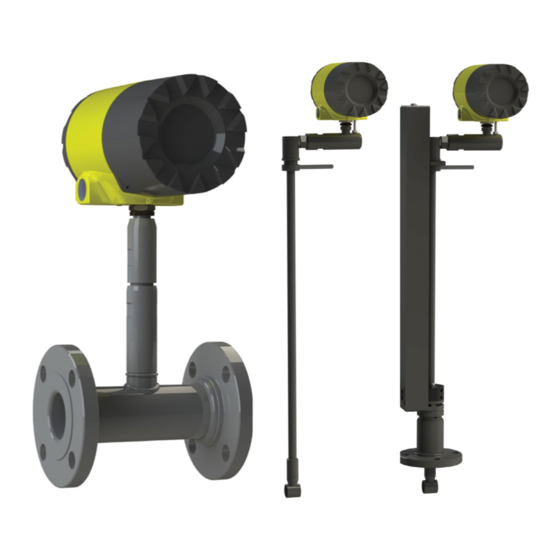
Armstrong AVF Installation And Operation Manual (137 pages)
Vortex Meter
Brand:
Armstrong
| Category:
Measuring Instruments
| Size: 16.16 MB
Table of Contents
Table of Contents
3
Chapter 1 Introduction
7
Using this Manual
7
Note and Safety Information
8
Receipt of System Components
8
Technical Assistance
8
Velocity Measurement
9
Vortex Shedding Frequency
9
Vortex Frequency Sensing
10
Flow Velocity Range
10
Pressure Drop
11
Minimum Back Pressure
12
Temperature Measurement
12
Pressure Measurement
12
Flow Meter Configurations
12
Multivariable Options
13
Line Size / Process Conditions / Materials
13
Flow Meter Electronics
13
Chapter 2 Installation
14
Installation Overview
14
Flow Meter Installation Requirements
14
Unobstructed Flow Requirements
15
Wafer-Style Flow Meter Installation
18
Flange-Style Flow Meter Installation
19
Cold Tap Guidelines
21
Hot Tap Guidelines
22
Flow Meter Insertion
23
Installing Meters with a Compression Connection
24
Insertion Calculation (Compression Type)
24
Installing Meters with a Packing Gland Connection
26
Insertion Calculation (Meters with Insertion Tool)
26
Insertion Calculation (Meters Without Insertion Tool)
29
Adjusting Meter Orientation
31
Display/Keypad Adjustment
31
Enclosure Adjustment
32
Loop Power Flow Meter Wiring Connections
33
Input Power Connections
34
DC Power Connections
34
4-20 Ma Output Connections
35
Load Resistance Versus Input Voltage
35
Pulse Output Connections
36
Isolated Pulse Output Using External Power Supply
36
Non-Isolated Pulse Output Using External Power Supply
36
Frequency Output Connections
37
Optional Backlight Connections
37
Isolated Frequency Output Using External Power Supply
37
Remote Electronics Wiring
38
Loop Power Volumetric Flowmeter Junction Box
38
High Power Flow Meter Wiring Connections
40
Input Power Connections
40
DC Power Connections
42
4-20 Ma Output Connections
43
Load Resistance Versus Input Voltage
43
Frequency Output Connections
44
Isolated Frequency Output Using External Power Supply
44
Pulse Output Connections
45
Non-Isolated Frequency Output Using Input Power Supply
45
Isolated Pulse Output Using External Power Supply
46
Non-Isolated Pulse Output Using Input Power Supply
46
Alarm Output Connections
47
Isolated Alarm Output Using External Power Supply
47
Remote Electronics Wiring
48
High Power Flow Meter Junction Box
48
Optional Input Electronics Wiring
49
Optional Energy EMS RTD Input Wiring
49
Optional External 4-20 Ma Input Wiring
50
External 4-20 Ma Input Wiring - External Power Supply
50
External 4-20 Ma Input Wiring - DC Powered Meter
50
Optional Contact Closure Input Wiring
51
External 4-20 Ma Input Wiring - AC Powered Meter
51
Chapter 3 Operating Instructions
52
Flow Meter Display/Keypad
52
Start up
53
Run Mode Screens
53
Using the Setup Menus
54
Programming the Flow Meter
55
Output Menu
56
Display Menu
58
Alarms Menu
59
Totalizer #1 Menu
60
Totalizer #2 Menu
61
Energy Menu
62
Fluid Menu
63
Units Menu
64
Time and Date Menu
65
Diagnostics Menu
66
Calibration Menu
67
Password Menu
68
Chapter 4 Serial Communications
69
HART™ Communications
69
Wiring
69
Loop Powered Meter Wiring (HART)
69
DC Powered Meter Wiring (HART)
70
AC Powered Meter Wiring (HART)
70
MODBUS Communications
79
Wiring
79
Menu Items
80
Register Definitions
82
BACNET™ MSTP Communications
89
1. Bacnet MS/TP Description
89
Baud Rates on the MS/TP Bus
89
Supported Bacnet Objects
90
ANNEX - Bacnet Protocol Implementation Conformance Statement
96
Acronyms and Definitions
102
Chapter 5 Troubleshooting and Repair
103
Hidden Diagnostics Menus
103
Level One Hidden Diagnostics Values
105
Level Two Hidden Diagnostics Values
106
Analog Output Calibration
108
Troubleshooting the Flow Meter
109
First Check Items
109
Record Values
109
Determine the Fault
111
Symptom: Output at no Flow
111
Symptom: Erratic Output
111
Symptom: no Output
112
Symptom: Meter Displays Temperature Fault
113
Symptom: Meter Displays Pressure Fault
113
Pressure Sensor Connector
113
Electronics Assembly Replacement
114
Returning Equipment to the Factory
115
Appendix A Product Specifications
116
Appendix B Approvals
124
Appendix C Flow Meter Calculations
126
Appendix D Glossary
131
Advertisement
Advertisement
Related Products
Armstrong AIM ST6700
Armstrong AMF
Armstrong AVI
Armstrong AVR 235
Armstrong AMC-210 Series
Armstrong Flo-Direct AFD-1500
Armstrong Flo-Direct AFD-14000
Armstrong ASF-H4 2-1/2NPT
Armstrong A95DF1E
Armstrong Flo-Direct AFD-4000
Armstrong Categories
Water Pump
Control Unit
Controller
Humidifier
Water System
More Armstrong Manuals
Login
Sign In
OR
Sign in with Facebook
Sign in with Google
Upload manual
Upload from disk
Upload from URL