
Related Manuals for Armstrong AMF


Summary of Contents for Armstrong AMF
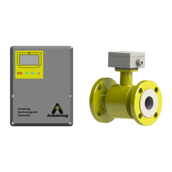
- Page 1 Armstrong Electromagnetic Flowmeter Installation & Operations Manual Remote Type Integral Type Please read and save these instructions 476-EN V1.1...
- Page 2 The following conventions are used through this manual: WARNING! Read the declaration carefully before starting any other action! Local safety regulations must be applied! CAUTION! Attention! Damage could occur to the device if handled inappropriately. Designs, materials, weights and performance ratings are approximate and subject to change without notice. Visit armstronginternational.com for up-to-date information. North America •...
-
Page 3: Table Of Contents
Table of Contents Table of Contents ............. 1.0 Introduction . -
Page 4: Introduction
Operation of the AMF is based on the electromagnetic induction law of Faraday. The AMF is used to measure the volume flow of conductive fluids in a closed pipeline. Examples of applicable liquids are: water, salt water, sewage, pulps, slurry, acid, alkali, or any mixture of liquids and solids which have a specific minimum of electric conductivity. -
Page 5: Features
1.2 Features *Structure Type: * Electrode Materials: Integral type or remote type 316L SS, Hastelloy B, Hastelloy C, Titanium or * Accuracy: Tantalum Standard version: ±0.5% of reading * Sensor Material: High-accuracy version: ±0.25% of reading - Measuring tube: stainless steel - Housing: carbon steel or stainless steel Accuracy not affected by variation of flow density, - Flange type: ANSI #150 or DIN... -
Page 6: Dimensions And Pressure Ratings
1.3 Dimensions and Pressure Ratings Dimension (in) Weight Nominal Inches Pressure Compact Remote 10.5 11.5 1025 1015 1145 1075 1075 1115 1245 1175 1000 1000 1175 1230 1360 1290 1200 1200 1405 1450 1580 1510 1400 1400 1630 1630 1760 1690 1239 1240... -
Page 7: Flow Measurement Principle
With the flowing fluid as the moving conductor and measuring- electrodes inside the flow-cell wall, the AMF detects an induced voltage which is proportional to the flow velocity. These velocity measurements are virtually independent of pressure, density, temperature and viscosity. Because of these operating principles, accurate measurements can be made of fluids containing solids such as ore slurry, and cellulose pulp. -
Page 8: Typical Applications
1.5 Typical Applications The AMF can be applied to a wide range of pipe flow measurements. Applicable liquids include pure liquids as well as mixtures of liquids and solids which have a minimum of electric conductivity. Examples are: • Water (hot water, chilled water, city water, sea water, waste water, etc.);... -
Page 9: Specifications
Structure Type Integral type, remote type, submersible type Figure 1.6 AMF Specifications Designs, materials, weights and performance ratings are approximate and subject to change without notice. Visit armstronginternational.com for up-to-date information. North America • Latin America • India • Europe / Middle East / Africa • China • Pacific Rim... -
Page 10: Installation And Measurement
90%. 2.2.2 Installing the Flowcell The flowcell should be installed by or under the supervision of a professional. When installing the AMF in an environment involving hazardous liquids please follow proper safety protocol. Please refer to Appendix E for installation recommendations Designs, materials, weights and performance ratings are approximate and subject to change without notice. -
Page 11: Wiring
Never install the flowmeter or do the wiring with power supply on! Your AMF will require a power supply of either 85VAC-250VAC; 20VDC-36VDC. Opening the flowmeter enclosure you should see seven terminal blocks. Refer to Figure 2.2 Terminal Connectors for details regarding these terminals. - Page 12 SIG1 Signal 1 SGND Signal Ground SIG2 Signal 2 Shielded Exciting1 To Separate Model Sensor Shielded Exciting2 EXT + Exciting Current EXT - Exciting Current - VDIN Current Two lines 24V Spots ICOUT Analog Current Output Analog Current Output ICCOM Analog Current Output Ground POUT Flow Frequency (Pulse) Output...
- Page 13 2.3.1 Terminals and Labels of Connectors in Circular Model (Integral Type Flowmeter) COM I+ COM P+ FUSE Figure 2.4 Connectors for Circular Model Symbols and Description of Connectors in Circular Pane Output Current for Flow Measurement COM: Output Current (Ground) for Flow Measurement Frequency(Pulse) Output for Bi-directional Flow COM: Frequency (Pulse) Output (Ground)
- Page 14 2.3.2 Labels and Connection of Signal Lines in Circular Model White Cable Red 12 Conductor Shielded Cable Black 12 Conductor Shielded Cable Red 10 Conductor Shielded Cable White 13 Conductor Shielded Cable Shield Screen Gray Shielded Cable Figure 2.5 Labels and connection of signal lines in circular model Signal lines labels in circular model: White twisted-pair cable (for exciting current): 12 Conductors (Red) 12 Conductors (Black)
- Page 15 Note: When the DIP switch next to terminal is set to ON places, the converter from its inside can provide +28Vpower supply and up-pull 10kΩ resistance to output Frequencies (PUL) to isolated OC gate, Alarm Output (ALMH.ALML), and Status Control (INSW).Therefore, when converter has frequency output and works with sensor together, DIP switch can be set as ON getting frequency signals from POUT and PCOM terminals.
- Page 16 Integrated Flow 1 2 3 4 5 6 Figure 2.6(c) Connection of electronic counter Low Limit Alarm DC Power Supply Upper Limit Alarm Figure 2.6(d) Connection of alarm output inside outside Pout ALMH ALML PCOM ALCOM Figure 2.6(e) Connection of OC gate Designs, materials, weights and performance ratings are approximate and subject to change without notice.
- Page 17 2.3.3(d) Grounding Please note that grounding is very important for guarantee the measurement accuracy as well as for safety protection. The contact area of copper Connector PE on Converter Cabinet for grounding should be larger than 1.6mm Contact resistance should be less than 10Ω. Please see Appendix D for earth grounding recommendations.
- Page 18 2.3.4(d) The connection of digital voltage output Pout User equipment Voltage input Pcom Inside Figure 2.7(a) The connection of digital voltage output 2.3.4(e) Digital output connect photoelectrical coupling (PLC etc.) Pout User inside equipment Pcom Figure 2.7(b) Digital output connect photoelectrical coupling Commonly user’s photoelectrical coupling current is about 10mA, so about E/R=10mA, E=5~24V.
- Page 19 Table of digital output parameter: POUT Parameter Test Condition Mini Typical Unit Voltage IC=100 mA Current Vol≤1.4V Frequency IC=100mA 5000 7500 Vcc=24V High voltage IC=100mA Low voltage IC=100mA 2.3.5 Simulation signal output and calculate 2.3.5a Simulation signal output There are two signal system: 0~10mA and 4~20mA, user can select from parameter setting. Simulation signal output inner is 24V under 0~20mA, it can drive 750Ω...
- Page 20 Converter Figure 2.8(a) AMF two connection Converter Figure 2.8(b) AMF three connection (power supply and current output are not insulated) Converter Designs, materials, weights and performance ratings are approximate and subject to change without notice. Visit armstronginternational.com for up-to-date information.
-
Page 21: Power Up
2.4 Power Up The AMF does not have a power ON/OFF switch. When it is connected to power, it will start to run automatically. After the power is turned on, the flowmeter will run a self-diagnostic program, checking first the hardware and then the software integrity. -
Page 22: Quick Start Menu Navigation
Step 1: Power On Upon power up of the AMF you will be prompted with the flow measurement window. The flow measurement window in Figure 2.5 provides the user with real-time volume and velocity readings as well as a programmable alarm indicator and flow units. -
Page 23: Menu Windows & Details
3.0 Menu Windows & Details The AMF has 5 different levels of passwords which allow access to different menu windows and the ability to change their parameter settings. To enter the password, from the main screen, press the MENU + ENT buttons simultaneously. For access to all menus, enter the factor set password 07206, otherwise: Level 1 password (set by manufacturer as 00521): Allows users to read-only privileges of parameter settings. -
Page 24: Table Of Parameter Setting Menu - Continued
3.2 Table of Parameter Setting Menu - continued Item No. Menu Display Setting Method Value Range Password Level Clr Sum Key Modify 0 ~ 99999 Snsr Code 1 Option Finished Y/M Snsr Code 2 User Set Product No. Field Type Option Type 1,2,3 Sensor Fact... -
Page 25: Parameter Details
2400, the user can select: 300, 1200, 2400, 4800, 9600, 19200, baud rate. Please refer to Appendix A for Modbus protocol 3.3.4 Snsr Size The AMF converters can be equipped with different sensors for different diameters of measuring pipes. The pipes diameters can range from 3mm to 3000mm. 3.3.5 Flow Unit... - Page 26 3.3.10 Flow Cutoff Flow cutoff is used to delete negligible small signals of flow volume. Set the flow cutoff slightly above the maximum reading during zero flow. 3.3.11 Cutoff Ena If Cutoff is enabled and flow is lower than the set value, the display of flowrate, speed and percentage and signal outputs are forced to zero.
- Page 27 This coefficient is used to select the length time of the ‘restrain cuspidal disturb’ and the unit is ms. If the duration is too short, The AMF will think that it is ‘cuspidal disturb’. If it is too long, the AMF. It also needs to select parameter in fact.
- Page 28 3.3.36 User’s password 1~4 Users can use 5 levels of passwords to correct these passwords. Reminder: Keep passwords in a safe place. 3.3.37 Analog Zero The analog output is zero calibrated by the factory and adjustments should NOT be made by the user. 3.3.38 Anlg Range Here you can adjust the analog output range (units are in mA).
-
Page 29: Warranty And Services
The products manufactured by Armstrong are warranted to be free from defects in materials and workmanship for a period of one year from the date of shipment to the original purchaser. Armstrong’s obligation should be limited to restoring the meter to normal operation or replacing the meter, at Armstrong’s choice, and shall be conditioned upon receiving written notice of any alleged defect within 10 days after its discovery. -
Page 30: Appendices
Appendices Appendix A - MODBUS COMMUNICATION PROTOCOL AMF communication protocol uses standard MODBUS RTU communication protocol. AMF device is defined as the slave. It supports half-duplex communication at 1200, 2400, 4800, 9600 or 19200 baud rate. The Master device must have a communication buffer (FIFO) for at least 11 bytes. - Page 31 3. Register Write Command 1) Master Command Format Device Address Function Code Register Address Data1 Data0 (8 bit) (8 bit) (16 bit) (High byte) (Low byte) (16 bit) 1~99 0000--0035 xxxx 2) Slave Response Format Device Address Function Code Register Address Data1 Data0 (8 bit)
- Page 32 2) Battery and Alarm 100AH High Byte Low Byte The register high byte is the battery level: 0-5 The register low byte is for alarm: BIT 0 - weak signal alarm BIT 1 - empty pipe alarm BIT 2 - system alarm (for battery powered unit) BIT 3 - upper limit alarm BIT 4 - lower limit alarm Register Table II...
-
Page 33: Appendix B - Hart Communication Protocol
Appendix B - HART COMMUNICATION PROTOCOL Please contact veris-sales@armstronginternational.com for detailed information Designs, materials, weights and performance ratings are approximate and subject to change without notice. Visit armstronginternational.com for up-to-date information. North America • Latin America • India • Europe / Middle East / Africa • China • Pacific Rim armstronginternational.com... -
Page 34: Appendix C - Profibus Communication Protocol
Appendix C - PROFIBUS COMMUNICATION PROTOCOL Please contact veris-sales@armstronginternational.com for detailed information Designs, materials, weights and performance ratings are approximate and subject to change without notice. Visit armstronginternational.com for up-to-date information. North America • Latin America • India • Europe / Middle East / Africa • China • Pacific Rim armstronginternational.com... -
Page 35: Appendix D - Earth Grounding
Appendix D - EARTH GROUNDING The sensor body must be grounded using grounding or bonding straps or grounding rings to protect flow signal against stray electrical noise and lightning. Well-grounded installation will make noise carried through sensor body so that the measuring area within sensor body is noise-free. -
Page 36: Lightning Protection Note
For pipe lines with cathodic protection: Connecting Wire Flow Grounding flange Copper wire, >4mm Earth Ground Ground resistance <10Ω LIGHTNING PROTECTION NOTE When installing, you need to connect the converter’s Earth terminal with the metal enclosure, and then to the earth ground reliably, because electrical current could flow from the earth ground through the metal enclosure by the gas discharger of a lightning protection device. -
Page 37: Appendix E - Flow Sensor Installation Recommendations
Appendix E - FLOW SENSOR INSTALLATION RECOMMENDATIONS Designs, materials, weights and performance ratings are approximate and subject to change without notice. Visit armstronginternational.com for up-to-date information. North America • Latin America • India • Europe / Middle East / Africa • China • Pacific Rim armstronginternational.com... - Page 38 Designs, materials, weights and performance ratings are approximate and subject to change without notice. Visit armstronginternational.com for up-to-date information. North America • Latin America • India • Europe / Middle East / Africa • China • Pacific Rim armstronginternational.com...
-
Page 39: Limited Warranty And Remedy
As a condition of enforcing any rights or remedies relating to Armstrong products, notice of any warranty or other claim relating to the products must be given in writing to Armstrong: (i) within 30 days of last day of the applicable warranty period, or (ii) within 30 days of the date of the manifestation of the condition or occurrence giving rise to the claim, whichever is earlier. - Page 40 Installation & Operations Manual Designs, materials, weights and performance ratings are approximate and subject to change without notice. Visit armstronginternational.com for up-to-date information. Armstrong International - VERIS Flow Measurement Group 5820 Glacier Way, Frederick, CO 80205 - USA Phone: 303-652-8550 Fax: 303-652-8552 armstronginternational.com 476-EN V1.1...
Need help?
Do you have a question about the AMF and is the answer not in the manual?
Questions and answers