Table of Contents
Advertisement
Quick Links
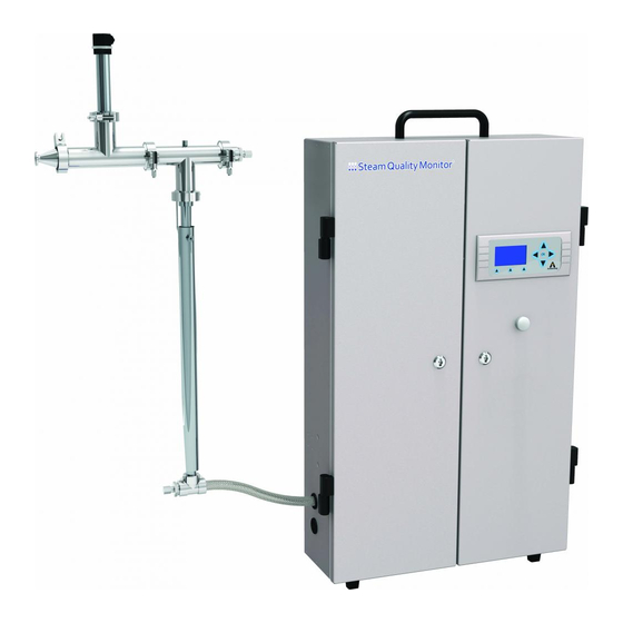
Steam QM-3 Steam Quality Monitor
Installation and Operation Manual
Certified by
IOM-245-V2.1
Armstrong International
Armstrong International
Parc Industriel des Hauts-Sarts, 2ème avenue 4, 4040 HERSTAL - BELGIUM
Tél : +32(0)4 240 90 90 Fax : +32 (0)4 240 40 33 armstrong
Keep this manual with equipment
for future reference.
armstronginternational.com
Advertisement
Table of Contents

Subscribe to Our Youtube Channel
Related Manuals for Armstrong Steam QM-3


Summary of Contents for Armstrong Steam QM-3
- Page 1 Installation and Operation Manual Certified by Keep this manual with equipment IOM-245-V2.1 for future reference. Armstrong International Armstrong International Parc Industriel des Hauts-Sarts, 2ème avenue 4, 4040 HERSTAL - BELGIUM Tél : +32(0)4 240 90 90 Fax : +32 (0)4 240 40 33 armstrong armstronginternational.com...
-
Page 2: Table Of Contents
Limited Warranty and Remedy ..Armstrong International Armstrong International Parc Industriel des Hauts-Sarts, 2ème avenue 4, 4040 HERSTAL - BELGIUM Phone : +32(0)4 240 90 90 Fax : +32 (0)4 240 40 33 armstrong armstronginternational.com... -
Page 3: Revision History
Yokogawa information deleted from document. 31/07/2020 page 8: Electrical parmameter - add : (±10 %) page 9: add Indore use and Pollution Degree 2 to General Consideration (Site Selection) § Page 1 of 30 Armstrong International Armstrong International IOM-245-V2.1 Steam QM-3... -
Page 4: Safety
Improper installation, start-up, operation, maintenance, or service may void warranty. You are encouraged to contact Armstrong International or its local sales representative for additional information. Service must be performed by a qualified person. Equipment must be disposed of according to applicable environmental requirements. -
Page 5: Abbreviations And Acronyms
Dryness Fraction (sometimes called steam Xmin is the lower dryness limit. Alarm 1 indicates the limit has been exceeded. Range is quality or moisture content) 0.85–0.95. Default is 0.95. Page 3 of 30 Armstrong International Armstrong International IOM-245-V2.1 Steam QM-3... -
Page 6: General Description
(NCG measurement is performed first. If it is within range, dryness and superheat measurements will be performed.) Armstrong strongly recommends that the Steam QM-3 unit be installed in one location and not used for checking multiple steam outlets. It is possible to use one unit for multiple locations and it could be installed for portability at customer's preference. -
Page 7: Calorimeter Assembly
Steam line from calorimeter to superheating chamber (not visible) Superheating chamber Drain (6 mm) T1 temperature transmitter T2 temperature transmitter Heating Element Steam to cabinet (flexible hose not shown) Calorimeter Assembly Page 5 of 30 Armstrong International Armstrong International IOM-245-V2.1 Steam QM-3... -
Page 8: Cabinet Exterior
(M12) Auxiliary (unused) Cooling water connections outlet Harting connector Steam from calorimeter Condensate drain Electrical connection and power switch (not visible) Wheel (back)/Foot (front) Cabinet Exterior Page 6 of 30 Armstrong International Armstrong International IOM-245-V2.1 Steam QM-3... -
Page 9: Cabinet Interior
Condensate pressure differential sensor Relay board with solenoid LED T3 temperature sensor Main screen (consult page 6) Condensate burette Cabinet steam inlet EV3 solenoid valve Cabinet condensate outlet Cabinet Interior Page 7 of 30 Armstrong International Armstrong International IOM-245-V2.1 Steam QM-3... -
Page 10: Specifications
1,5 kg/h (3,3 lbs/h ) @ 3 barg (45 psig) Estimated water consumption 15 L/h (4 gal/h ) @ 10 °C (50 °F) Electrical 115/230 VAC (±10 %) 50/60 Hz 100 W Specifications Page 8 of 30 Armstrong International Armstrong International IOM-245-V2.1 Steam QM-3... -
Page 11: Installation
Unit must be installed with the following utilities nearby: • Cooling water supply • Drain • Grounded power source with required voltage (alternative grounding of unit is permissible, but grounding is required) General Considerations (Site Selection) Page 9 of 30 Armstrong International Armstrong International IOM-245-V2.1 Steam QM-3... -
Page 12: Typical Installation
• Installation is highly variable based on site requirements. • Connections shown below are typical. • Contact Armstrong for variations as required. • The cable connecting Harting Plug to the sensors can not be looped. - Page 13 Loosen clamp between calorimeter and heating chamber. Reattach linking pipe Tighten clamp Screw plug on unused connection Remove plug from alternate connection point Rotate heating chamber 180° Typical Installation Page 11 of 30 Armstrong International Armstrong International IOM-245-V2.1 Steam QM-3...
- Page 14 Maximum inlet pressure is 90 psi (6 bar). Tubing diameter is 0.23" (6 mm). Note: Armstrong recommends deionized, R/O, or softened water, although tap water is permissible. Armstrong provides as a standard a 394" (10 meter) hose. Plumb both cooling water and condensate discharges to drain.
- Page 15 Modbus protocol. Note: Modbus settings may need to be changed; see "Advanced Setting Menu" on p. 17. (See appendix three on p. 29 for Modbus connection information.) Typical Installation Page 13 of 30 Armstrong International Armstrong International IOM-245-V2.1 Steam QM-3...
-
Page 16: Start-Up Procedure
Note: Parameters will display in about 10 minutes (may require up to 30 minutes if condenser is empty). Check for leaks and tighten connections as necessary. Page 14 of 30 Armstrong International Armstrong International IOM-245-V2.1 Steam QM-3... -
Page 17: Software Navigation
Ringing bell symbol accesses alarm settings menu. Option keys Down arrow symbol displays subsidiary EN285 screen. [psi] [ppm] 18.3 [kg/h] EN285 EN285 returns to initial screen. Standard Screens Page 15 of 30 Armstrong International Armstrong International IOM-245-V2.1 Steam QM-3... - Page 18 • Navigate arrow (–>) to alarm or default using arrow keys () as appropriate. • Press "OK." Note: Alarms and defaults cannot be reset over Modbus connection. Standard Screens Page 16 of 30 Armstrong International Armstrong International IOM-245-V2.1 Steam QM-3...
-
Page 19: Special Screens
Navigation is same as screen above. Scroll using up/down arrows ( or). With arrow (–>) at left of digits you want press ok. Calibration PSensor 0barg 3barg Special Screens Page 17 of 30 Armstrong International Armstrong International IOM-245-V2.1 Steam QM-3... - Page 20 64.3 • 10 if T1 < 212 °F (100 °C) (no steam) • > 1000 if superheated steam • 850–1000 (dryness fraction x 1000) during normal operation Special Screens Page 18 of 30 Armstrong International Armstrong International IOM-245-V2.1 Steam QM-3...
-
Page 21: Troubleshooting
Troubleshooting Components and water may be hot. Disconnect power before performing electrical work. If problem cannot be resolved, contact Armstrong. Power Light /Display Off Power switch Turn on switch. Power Check fuses in light Check power cable. switch. Check switch on Check F2 fuse. - Page 22 Check EV3 (see “Solenoid Check tubing for Check for plugged circulating? Valve” on p. 23). blockage. condenser. Check: 1. Cooling water temperature 2. Cooling water pressure 3. Orifice 4. T1 5. Df6 Page 20 of 30 Armstrong International Armstrong International IOM-245-V2.1 Steam QM-3...
- Page 23 (remove and clean or replace as necessary) Conden- Wait for unit to cycle. (Contact sate overfilling Armstrong if it does not.) burette? 1. Remove tubing to burette. Check EV2 (see “Solenoid 2. Remove water from tubing. Go to “NCG Burette Overflowing.”...
- Page 24 Reduce steam pressure below 60 psig (4 barg). Check T2. T2 < 1. Calibration 356 °F Check heating element function. 2. Wiring connections (180 °C)? 3. Wires Reset Df6. Page 22 of 30 Armstrong International Armstrong International IOM-245-V2.1 Steam QM-3...
- Page 25 Coil Magnetic 1. Contacts burnt/melted or field present Replace coil. 2. DIN connector cold with power at coil? 3. All wiring connections present? Replace solenoid valve or call Armstrong. Page 23 of 30 Armstrong International Armstrong International IOM-245-V2.1 Steam QM-3...
-
Page 26: Software Update
6. Plug and turn on the QM-3, light is ON and screen is activated. 7. Check the version software in the code menu (press simultaneously on and ). Page 24 of 30 Armstrong International Armstrong International IOM-245-V2.1 Steam QM-3... -
Page 27: Component And Parts List
BURKERT 3/2 solenoid valve (EV2) D44121 JUMO PT100 (T3) D44122 JUMO Differential pressure sensor D44123 Orifice Plate with Gasket D40020 Gasket PTFE for 1/2'' flexible hose (bag with 3 pieces) D53335 Page 25 of 30 Armstrong International Armstrong International IOM-245-V2.1 Steam QM-3... -
Page 28: Product Certifications
• EN 60204-1: Safety of machinery – Electrical Equipment of machines – Part 1: General requirements • EN 292 Parts 1 & 2: Safety of machinery basic principle mechanical design CONFORMS TO UL STD 61010-1 CERTIFIED TO CSA STD C22.2 NO. 61010-1 4007613 Page 26 of 30 Armstrong International Armstrong International IOM-245-V2.1 Steam QM-3... -
Page 29: Appendix One: Wiring Diagram
Appendix One: Wiring Diagram Page 27 of 30 Armstrong International Armstrong International IOM-245-V2.1 Steam QM-3... -
Page 30: Appendix Two: Principle Schematic
Appendix Two: Principle Schematic Page 28 of 30 Armstrong International Armstrong International IOM-245-V2.1 Steam QM-3... -
Page 31: Appendix Three
The logger end of the cord must be wired by the customer. Program the logger with the following information. Note: The Modbus address and the mode of communication is define in the Steam QM-3 Advanced Setting Menu, see p. 17. #3, RS - (B) #1, RS + (A) -
Page 32: Limited Warranty And Remedy
As a condition of enforcing any rights or remedies relating to Armstrong products, notice of any warranty or other claim relating to the products must be given in writing to Armstrong: (i) within 30 days of last day of the applicable warranty period, or (ii) within 30 days of the date of the manifestation of the condition or occurrence giving rise to the claim, whichever is earlier.
Need help?
Do you have a question about the Steam QM-3 and is the answer not in the manual?
Questions and answers