
Related Manuals for BCM ECM-WHL

Summary of Contents for BCM ECM-WHL
- Page 1 ECM-WHL 8th Gen Intel® Whiskey Lake 3.5”Micro Module User’s Manual Ed –12 October 2020 Part No. E2047394603R...
- Page 2 We assume no responsibility or liability for the use of the described product(s), conveys no license or title under any patent, copyright, or masks work rights to these products, and makes no representations or warranties that 2 ECM-WHL User’s Manual...
- Page 3 For the most frequently asked questions, you can easily find answers in your product documentation. These answers are normally a lot more detailed than the ones we can give over the phone. So please consult the user’s manual first. ECM-WHL User’s Manual...
- Page 4 A product returned without proof of the purchase date is not eligible for warranty service. Write the RMA number visibly on the outside of the package and ship it prepaid to your dealer. 4 ECM-WHL User’s Manual...
-
Page 5: Table Of Contents
Front Panel connector (JFP1) ....................27 2.3.18 PC Buzzer connector (JBZ1) ..................... 28 Cooler Installation ....................29 Heatsink/Heat spreader Installation ................ 30 3.BIOS Setup ........................31 Introduction ......................32 Starting Setup ......................32 Using Setup ......................33 Getting Help ......................34 ECM-WHL User’s Manual... - Page 6 Board & Panel Configuration ....................66 3.6.4 Security ............................67 3.6.4.1 Secure Boot ........................... 68 3.6.4.1.1 Key Management ........................69 3.6.5 Boot .............................. 70 3.6.6 Save and exit ..........................71 3.6.6.1 Save Changes and Reset ...................... 71 6 ECM-WHL User’s Manual...
- Page 7 Install ME Driver ...................... 75 Install VGA Driver ....................76 Install Audio Driver (For Realtek ALC892) .............. 78 Install Ethernet Driver ....................79 Install HDMI_CEC Driver ..................81 Install IRST Driver ....................83 5. Mechanical Drawing ....................85 ECM-WHL User’s Manual...
-
Page 8: Getting Started
1.2 Packing List Before you begin installing your single board, please make sure that the following materials have been shipped: 1 x 3.5” ECM-WHL Micro Module 1 x Cable set contains the followings: ... -
Page 9: Document Amendment History
User’s Manual 1.3 Document Amendment History Revision Date Comment October 2019 Initial Release February 2020 Update 2.3.4 JAT1 April 2020 Add 2.5 Heatsink/Heat spreader Installation October 2020 Update 2.3.4 JAT1 ECM-WHL User’s Manual... -
Page 10: Manual Objectives
We strongly recommend that you study this manual carefully before attempting to set up ECM-WHL or change the standard configurations. Whilst all the necessary information is available in this manual we would recommend that unless you are confident, you contact your supplier for guidance. -
Page 11: System Specifications
1 x LED for Data Access 1 x Line-Out Audio 1 x Mic-In Onboard I/O Connector 2 x USB 2.0 1 x RS-232 GPIO 1 x 8-bit GPIO 1 x LPC 1 x SPI SMBus 1 x SMBus ECM-WHL User’s Manual 11... - Page 12 1 x Intel i211AT LAN Chip 1 x Intel i219LM Ethernet 10/100/1000 Base-Tx GbE compatible Interface Connector 2 x RJ45 with ACT/LINK and SPEED LEDs Mechanical & Environmental Power +12Vdc Requirement ACPI Single power ATX Support S0,S3, S4, S5 12 ECM-WHL User’s Manual...
- Page 13 10G, IEC 60068-2-27, Half Sine, 11ms, Z Axis Drop Test ISTA 2A, IEC-60068-2-32 Test : Ed, 1 Corner, 3 Edges, 6 Faces OS Support (listed in accordance Windows 10 with Intel Linux document) Note: Specifications are subject to change without notice. ECM-WHL User’s Manual 13...
-
Page 14: Architecture Overview-Block Diagram
ECM-WHL User’s Manual 1.6 Architecture Overview—Block Diagram The following block diagram shows the architecture and main components of ECM-WHL 14 ECM-WHL User’s Manual... -
Page 15: Hardware Configuration
User’s Manual 2. Hardware Configuration ECM-WHL User’s Manual 15... -
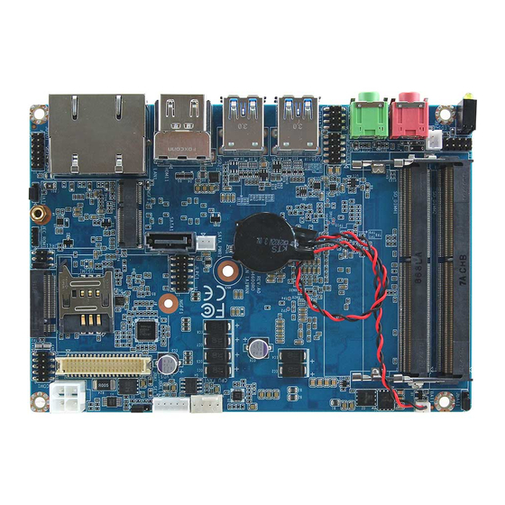
Page 16: Product Overview
ECM-WHL User’s Manual 2.1 Product Overview 16 ECM-WHL User’s Manual... -
Page 17: Jumper And Connector List
Matching Connector: JST PHR-5 CPU fan connector 4 x 1 wafer, pitch 2.54mm CPU_FAN1 Serial Port 1 connector 5 x 2 header, pitch 2.00mm JCOM1 JDIO1 General purpose I/O connector 6 x 2 wafer, pitch 2.00mm ECM-WHL User’s Manual 17... - Page 18 3 x 1 header, pitch 2.00mm SATA_PWR1 SATA Power connector 2 x 1 wafer, pitch 2.00mm SATA1 Serial ATA connector HDMI1 HDMI connector 2 x DDR4 SODIMM socket SO_DIMM1/2 Mic-in audio jack MIC1 Line-out audio jack LOUT1 SIM card slot USIM1 18 ECM-WHL User’s Manual...
-
Page 19: Setting Jumpers & Connectors
User’s Manual 2.3 Setting Jumpers & Connectors 2.3.1 Serial port 1 pin9 signal select (JRI1) Ring* +12V * Default 2.3.2 Clear CMOS (JBAT1) Normal* Clear CMOS * Default ECM-WHL User’s Manual 19... -
Page 20: Lcd Backlight Brightness Adjustment (Jbkl_Sel1)
ECM-WHL User’s Manual 2.3.3 LCD backlight brightness adjustment (JBKL_SEL1) PWM Mode* DC Mode * Default 2.3.4 AT/ATX Input power select (JAT1) * Default 20 ECM-WHL User’s Manual... -
Page 21: Lcd Inverter Connector (Jbkl1)
User’s Manual 2.3.5 LCD inverter connector (JBKL1) Signal VBRIGHT BKLEN +12V 2.3.6 CPU fan connector (CPU_FAN1) Signal +12V EC_R_TACH0 FAN_PWM0 ECM-WHL User’s Manual 21... -
Page 22: Serial Port 1 Connector (Jcom1)
Serial port 1 connector (JCOM1) Signal PIN PIN Signal COM_DCD#_1 COM_RXD_1 COM_TXD_1 COM_DTR#_1 COM_DSR#_1 COM_RTS#_1 COM_CTS#_1 NRIA# 2.3.8 General purpose I/O connector (JDIO1) Signal PIN PIN Signal DIO_GP20 DIO_GP10 DIO_GP21 DIO_GP11 DIO_GP22 DIO_GP12 DIO_GP23 DIO_GP13 SMB_SCL_S0 SMB_SDA_S0 22 ECM-WHL User’s Manual... -
Page 23: Sata Power Connector (Sata_Pwr1)
User’s Manual 2.3.9 SATA Power connector (SATA_PWR1) Signal 2.3.10 Power connector (PWR1) Signal Signal +12V +12V ECM-WHL User’s Manual 23... -
Page 24: Lvds Connector (Jlvds1)
LVDS_CLK1_N LVDS_CLK2_P LVDS_CLK1_P LVDS_DATA7_N 29 30 LVDS_DATA6_N LVDS_DATA7_P 27 28 LVDS_DATA6_P LVDS_DATA5_N 23 24 LVDS_DATA4_N LVDS_DATA5_P 21 22 LVDS_DATA4_P LVDS_DATA3_N 17 18 LVDS_DATA2_N LVDS_DATA3_P 15 16 LVDS_DATA2_P LVDS_DATA1_N 11 12 LVDS_DATA0_N LVDS_DATA1_P 10 LVDS_DATA0_P +3.3V +3.3V 24 ECM-WHL User’s Manual... -
Page 25: Usb2.0 Connector (Jusb1)
User’s Manual 2.3.12 USB2.0 connector (JUSB1) Signal PIN PIN Signal +5VSB USB_R_DN7 USB_R_DP7 USB_R_DP8 USB_R_DN8 +5VSB 2.3.13 SPI connector (JSPI1) Signal PIN PIN Signal +3.3VSB SPI_CS0# SPI_CLK SPI_MISO SPI_MOSI BIOS_HOLD# BIOS_WP# ECM-WHL User’s Manual 25... -
Page 26: Ec Debug Connector (Jec_Rom1)
ECM-WHL User’s Manual 2.3.14 EC Debug connector (JEC_ROM1) Signal EC_SMCLK_DEBUG EC_SMDAT_DEBUG 2.3.15 Battery connector (BAT1) Signal +RTCBAT 26 ECM-WHL User’s Manual... -
Page 27: Lpc Connector (Jlpc1)
User’s Manual 2.3.16 LPC connector (JLPC1) Signal PIN PIN Signal LPC_AD0 +3.3V LPC_AD1 RST_TPM# LPC_AD2 LPC_LFRAME# LPC_AD3 CLK2_LPC1_DEBUG LPC_SERIRQ 2.3.17 Front Panel connector (JFP1) Signal PIN PIN Signal PWRBTN_IN# PM_SYSRST# FP_PWR_LED+ PWR_LED# HDD_LED# CASE_OPEN# ECM-WHL User’s Manual 27... -
Page 28: Pc Buzzer Connector (Jbz1)
ECM-WHL User’s Manual 2.3.18 PC Buzzer connector (JBZ1) Signal SOC_SPKR_R 28 ECM-WHL User’s Manual... -
Page 29: Cooler Installation
User’s Manual 2.4 Cooler Installation 1. Please remove release paper. 2. Please follow the below picture to install the cooler and cooler wire. And fix the 5 screw of cooler and finish the installation. Step1: Step2: Step3: ECM-WHL User’s Manual 29... -
Page 30: Heatsink/Heat Spreader Installation
ECM-WHL User’s Manual 2.5 Heatsink/Heat spreader Installation 1. Using 5 screws to lock the Heatsink/Heat spreader from PCB backside. 30 ECM-WHL User’s Manual... -
Page 31: Bios Setup
User’s Manual 3.BIOS Setup ECM-WHL User’s Manual 31... -
Page 32: Introduction
If the message disappears before you respond and you still wish to enter Setup, restart the system to try again by turning it OFF then ON or pressing the "RESET" button on the system case. You may also restart by simultaneously pressing <Ctrl>, <Alt>, and <Delete> keys. 32 ECM-WHL User’s Manual... -
Page 33: Using Setup
Note: Some of the navigation keys differ from one screen to another. To Display a Sub Menu Use the arrow keys to move the cursor to the sub menu you want. Then press <Enter>. A “” pointer marks all sub menus. ECM-WHL User’s Manual 33... -
Page 34: Getting Help
BIOS Vendor and your systems manufacturer to provide the absolute maximum performance and reliability. Even a seemingly small change to the chipset setup has the potential for causing you to use the override. 34 ECM-WHL User’s Manual... -
Page 35: Bios Setup
<Enter> to accept and enter the sub-menu. 3.6.1 Main Menu This section allows you to record some basic hardware configurations in your computer and set the system clock. ECM-WHL User’s Manual 35... -
Page 36: System Language
Note: The BIOS setup screens shown in this chapter are for reference purposes only, and may not exactly match what you see on your screen. 3.6.2 Advanced Menu This section allows you to configure your CPU and other system devices for basic operation through the following sub-menus. 36 ECM-WHL User’s Manual... -
Page 37: Connectivity Configuration
Integrated solution (CNVi) will be enabled; [Disable Auto Detection[Default] Integrated] disables Integrated Solution. NOTE: When CNVi is present, the GPIO pins that are used for radio. Disabled[Default] Seriallo UART0 needs to be enabled to select BT Discrete Bluetooth Module Thunder Peak Module. ECM-WHL User’s Manual 37... -
Page 38: Wwan Configuration
ECM-WHL User’s Manual 3.6.2.1.1 WWAN Configuration Item Option Description Enabled WWAN Device Enable or Disable M.2 WWAN Device. Disabled[Default] 3.6.2.2 CPU Configuration Use the CPU configuration menu to view detailed CPU specification and configure the CPU. 38 ECM-WHL User’s Manual... -
Page 39: Power & Performance
When enabled, a VMM can utilize the additional Intel (VMX) Virtualization Disabled hardware capabilities provided by Vanderpool Technology Enabled[Default] Technology. All[Default] Number of cores to enable in each processor Active Processor Cores package. 3.6.2.3 Power & Performance ECM-WHL User’s Manual 39... -
Page 40: Cpu - Power Management Control
Speed Step or Intel Speed Shift to be available and Disabled enabled). Enabled[Default], C States Enable/Disable CPU Power Management. Disabled Enabled[Default], Enable/Disable C1E. When enabled, CPU will switch Enhanced C-States Disabled to minimum speed when all cores enter C-State. 40 ECM-WHL User’s Manual... - Page 41 SKUs: This value must be between Min Power. Power Limit 2 value in Milli Watts. BIOS will round to the nearest 1/8W when Power Limit 2 programming. 0= no custom override. For 12.50W, enter 12500. Processor applies ECM-WHL User’s Manual 41...
-
Page 42: Gt - Power Management Control
Check to enable render RC6(Render Standby) Disabled standby support. Default Max Frequency[Default] 100Mhz/150Mhz/200Mhz/250Mhz/300Mhz /350Mhz/400Mhz/450Mhz/500Mhz/550Mhz Maximum GT frequency Auto Updated. /600Mhz/650Mhz/700Mhz/750Mhz/800Mhz /850Mhz/900Mhz/950Mhz/1000Mhz/1050Mhz /1100Mhz/1150Mhz/1200Mhz Enabled: Disables Turbo GT Disable Turbo GT Enabled frequency. Disabled: GT frequency Disabled[Default] frequency is not limited. 42 ECM-WHL User’s Manual... -
Page 43: Pch-Fw Configuration
When disabled AMT BIOS Features are no longer Disabled, supported and user is no longer able to access AMT BIOS Features Enabled[Default] MEBx Setup. Note: This option does not disable Manageability Features in FW. 3.6.2.4.1 Firmware Update Configuration ECM-WHL User’s Manual 43... -
Page 44: Trusted Computing
O.S. will not show Security Device. TCG EFI protocol Enable[Default] and INT1A interface will not be available. Disable, SHA-1 PCR Bank Enables or Disables SHA-1 PCR Bank. Enable[Default] Disable, SHA256 PCR Bank Enables or Disables SHA256 PCR Bank. Enable[Default] 44 ECM-WHL User’s Manual... -
Page 45: Apci Settings
Hibernate (OS/S4 Sleep State). This Enable Hibernation Enabled[Default], option may not be effective with some Select the highest ACPI sleep state the Suspend Disabled, ACPI Sleep State system will enter when the SUSPEND S3 (Suspend to RAM)[Default] button is pressed. ECM-WHL User’s Manual 45... -
Page 46: It8528 Super Io Configuration
Please refer to 3.6.2.7.1 for more information. Item Description Serial Port 1 Configuration Set Parameters of Serial Port 1 (COMA). 3.6.2.7.1 Serial Port 1 Configuration Item Option Description Enabled[Default], Serial Port Enable or Disable Serial Port (COM). Disabled 46 ECM-WHL User’s Manual... -
Page 47: Hw Monitor
Enable or disable System wake on alarm event. Select Disabled[Default], Fixed Time, system will wake on the hr::min::sec specified. Wake system from S5 Fixed Time Select Dynamic Time, System will wake on the current time Dynamic Time + Increase minute(s). ECM-WHL User’s Manual 47... -
Page 48: Serial Port Console Redirection
3.6.2.10.1 Legacy Console Redirection Settings Item Option Description Select a COM port to display redirection of Redirection COM Port COM0[Default] Legacy OS and Legacy OPROM Messages. 80x24[Default] On Legacy OS, the Number of Rows and Resolution 80x25 Columns supported redirection. 48 ECM-WHL User’s Manual... -
Page 49: Usb Configuration
Mass storage device emulation type. ‘AUTO’ Auto[Default] Floppy enumerates devices according to their media Mass Storage Devices Forced FDD format. Optical drives are emulated as ‘CDROM’, drives with no media will be Hard Disk CD-ROM emulated according to a drive type. ECM-WHL User’s Manual 49... -
Page 50: Network Stack Configuration
ECM-WHL User’s Manual 3.6.2.12 Network Stack Configuration Item Options Description Enabled Network Stack Enable/Disable UEFI Network Stack. Disabled[Default] 3.6.3 Chipset 50 ECM-WHL User’s Manual... -
Page 51: System Agent (Sa) Configuration
User’s Manual 3.6.3.1 System Agent (SA) Configuration Item Option Description Enabled[Default] VT-d VT-d capability. Disabled 3.6.3.1.1 Memory Configuration ECM-WHL User’s Manual 51... -
Page 52: Graphics Configuration
Select the card used on the platform Auto: Skip Auto[Default] GPIO based Power Enable to dGPU Elk Creek Select PCIE Card Elk Creek 4 4: DGPU Power Enable = ActiveLow PEG Eval : PEG Eval DGPU Power Enable= ActiveHigh. 52 ECM-WHL User’s Manual... -
Page 53: Pch-Io Configuration
User’s Manual 3.6.3.2 PCH-IO Configuration Item Option Description Disabled PCH LAN Controller Enable/Disable onboard NIC. Enabled[Default] 3.6.3.2.1 PCI Express Configuration ECM-WHL User’s Manual 53... - Page 54 L0s State AUTO – BIOS auto ASPM7 configure DISABLE – Disables ASPM. L0sL1 Auto Disabled, L1 Substates L1.1 PCI Express L1 Substates settings. L1.1 & L1.2[Default] Auto[Default] Gen1 PCIe Speed Configure PCIe Speed. Gen2 Gen3 54 ECM-WHL User’s Manual...
- Page 55 L0s State AUTO – BIOS auto ASPM11 configure DISABLE – Disables ASPM. L0sL1 Auto Disabled, L1 Substates L1.1 PCI Express L1 Substates settings. L1.1 & L1.2[Default] Auto[Default] Gen1 PCIe Speed Configure PCIe Speed. Gen2 Gen3 ECM-WHL User’s Manual 55...
- Page 56 L0s State AUTO – BIOS auto ASPM12 configure DISABLE – Disables ASPM. L0sL1 Auto Disabled, L1 Substates L1.1 PCI Express L1 Substates settings. L1.1 & L1.2[Default] Auto[Default] Gen1 PCIe Speed Configure PCIe Speed. Gen2 Gen3 56 ECM-WHL User’s Manual...
-
Page 57: Sata And Rst Configuration
State Drive or Hard Disk Drive. Enabled[Default] Port 1 Enable or Disable SATA Port. Disabled Hard Disk Drive[Default] Identify the SATA port is connected to Solid SATA Device Type Solid State Drive State Drive or Hard Disk Drive. ECM-WHL User’s Manual 57... - Page 58 To set RAID configuration, please follow the instruction below. Set RAID 0 (DATA Striping) Step 1: - Select “SATA mode selection” as “Intel RST Premium with Intel Optane System Acceleration” - Save and Reset system 58 ECM-WHL User’s Manual...
- Page 59 User’s Manual Step 2: Enter “Intel® Rapid Storage Technology” Step 3: Enter “Create RAID Volume” ECM-WHL User’s Manual 59...
- Page 60 ECM-WHL User’s Manual Step 4: Enter “Name “as “name of raid “and Set “RAID Level” as “RAID0” Step 5: - Select disk SATA 0.0 and SATA 0.1 - Select “Strip Size” - Select “Capacity” - Enter “Create Volume” 60 ECM-WHL User’s Manual...
- Page 61 User’s Manual Step 6: Completed. This page show the information of raid created by user Delete Raid 0: Step1: Enter “Delete” ECM-WHL User’s Manual 61...
- Page 62 ECM-WHL User’s Manual Step 2: Select “Yes “to delete RAID Set RAID 1 (DATA Mirroring) Step1: Enter “Create RAID Volume” 62 ECM-WHL User’s Manual...
- Page 63 - Set “RAID Level “ as “RAID1” - Select disk “SATA 0.0” and ”SATA 0.1” - Select “Strip Size” - Select “Capacity” - Enter “Create Volume” Step 3: Raid 1 be created. Select”Volume1” to see detail. ECM-WHL User’s Manual 63...
- Page 64 ECM-WHL User’s Manual Step 4: Completed. This page show the information of raid created by user. Delete Raid 1 Step1: Enter “Delete” 64 ECM-WHL User’s Manual...
-
Page 65: Hd Audio Configuration
Step2: Select “Yes” to delete RAID 3.6.3.2.3 HD Audio Configuration Item Option Description Control Detection of the HD-Audio device. Disable = HDA Disabled HD Audio will be unconditionally disabled Enabled = HDA will be Enabled[Default] unconditionally enabled. ECM-WHL User’s Manual 65... -
Page 66: Board & Panel Configuration
1680x1050 24/2 Panel Brightness Control BIOS[Default] Panel Brightness Control Method. 1.BIOS Method OS Driver 2.OS Driver. Select Panel(eDP/LVDS) back light PWM Panel Brightness duty. 100%[Default] 200[Default] Panel Back Light PWM Select Panel(eDP/LVDS) back light PWM Frequency Frequency. 66 ECM-WHL User’s Manual... -
Page 67: Security
30 min Disabled Wake Up by Ring Wake Up by Ring from S3/S4/S5. Enabled[Default] Disabled Enable/Disabled USB Standby Power USB Standby Power Enabled[Default] during S3/S4/S5. 3.6.4 Security Administrator Password Set setup Administrator Password User Password ECM-WHL User’s Manual 67... -
Page 68: Secure Boot
Platform Key(PK) is enrolled and the System is in User Enabled mode. The mode change requires platform reset. Secure Boot mode selector: Standard/Custom. In Standard Secure Boot Mode Custom mode Secure Boot Variables can be configured Custom[Default] without authentication. 68 ECM-WHL User’s Manual... -
Page 69: Key Management
User’s Manual 3.6.4.1.1 Key Management Item Option Description Install factory default Secure Boot keys after Disabled[Default] Factory Key Provision the platform reset and while the System is in Enabled Setup mode. ECM-WHL User’s Manual 69... -
Page 70: Boot
Setup Prompt Timeout 1~ 65535 key. 65535(0xFFFF) means indefinite waiting. Bootup NumLock State Select the keyboard NumLock state Off[Default] Disabled[Default] Quiet Boot Enables or disables Quiet Boot option Enabled Boot Option #1 Set the system boot order. 70 ECM-WHL User’s Manual... -
Page 71: Save And Exit
Reset the system after saving the changes. 3.6.6.2 Discard Changes and Reset Any changes made to BIOS settings during this session of the BIOS setup program are discarded. The setup program then exits and reboots the controller. ECM-WHL User’s Manual 71... -
Page 72: Restore Defaults
This option restores all BIOS settings to the factory default. This option is useful if the controller exhibits unpredictable behavior due to an incorrect or inappropriate BIOS setting. 3.6.6.4 Launch EFI Shell from filesystem device Attempts to Launch EFI Shell application (Shellx64.efi) from one of the available filesystem devices. 72 ECM-WHL User’s Manual... -
Page 73: Drivers Installation
User’s Manual 4. Drivers Installation Note: Installation procedures and screen shots in this section are for your reference and may not be exactly the same as shown on your screen. ECM-WHL User’s Manual 73... -
Page 74: Install Chipset Driver
Windows 10 operation system. If the warning message appears while the installation process, click Continue to go on. Step 3. Click Install. Step 4. Setup completed. Step1. Click Next. Step 2. Click Accept. 74 ECM-WHL User’s Manual... -
Page 75: Install Me Driver
Continue to go on. Step 3. Click Next to continue installation. Step 4. Installing. Step1. Click Next to start installation. Step 2. Click Next. Step 5. Click Finish to complete setup. ECM-WHL User’s Manual 75... -
Page 76: Install Vga Driver
Note: The installation procedures and screen shots in this section are based on Windows 10 operation system. Step 3. Click Next. Step 4. Click Next. Step 1. Click Next to continue installation. Step 5. Click Next. Step 6. Click Yes. 76 ECM-WHL User’s Manual... - Page 77 User’s Manual Step 6. Click Finish to complete setup. ECM-WHL User’s Manual 77...
-
Page 78: Install Audio Driver (For Realtek Alc892)
4.4 Install Audio Driver (For Realtek ALC892) Note: The installation procedures and screen shots in this section are based on Windows 10 operation system. Step 3. Click Finish to complete the setup Step 1. Click Next to continue setup. Step 2. Installing. 78 ECM-WHL User’s Manual... -
Page 79: Install Ethernet Driver
Windows 10 operation system. Step 3. Click Next. Step 1. Click Install Drivers and Software to continue installation. Step 4. Click Next. Step 2. Click Next. Step 5. Click Install. ECM-WHL User’s Manual 79... - Page 80 ECM-WHL User’s Manual Step 6. Installing. Step 7. Click Finish to complete setup. 80 ECM-WHL User’s Manual...
-
Page 81: Install Hdmi_Cec Driver
3. Please use HDMI1 first if single device (TV/Monitor) will be connected. Step 3. Click Next. 4. HDMI-CEC supports ON/OFF function only. Step 1. Click Install to continue installation. Step 4. Click Next. Step 2. Click Next. Step 5. Click Next. ECM-WHL User’s Manual 81... - Page 82 ECM-WHL User’s Manual Step 6. Install complete. 82 ECM-WHL User’s Manual...
-
Page 83: Install Irst Driver
Note: The installation procedures and screen shots in this section are based on Windows 10 operation system. Step 3. Click Next. Step 1. Click Next to continue installation. Step 4. Click Next. Step 2. Click Next. Step 5. Click Next. ECM-WHL User’s Manual 83... - Page 84 ECM-WHL User’s Manual Step 6. Installing. Step 7. Click Finish to complete setup. 84 ECM-WHL User’s Manual...
-
Page 85: Mechanical Drawing
User’s Manual 5. Mechanical Drawing ECM-WHL User’s Manual 85... - Page 86 ECM-WHL User’s Manual Unit: mm 86 ECM-WHL User’s Manual...
Need help?
Do you have a question about the ECM-WHL and is the answer not in the manual?
Questions and answers