Advertisement
Quick Links
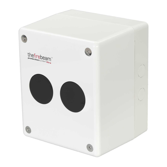
FireBeam Xtra
Servo-Motorized Beam
Detector for Automatic
Alignment & Displacement
Compensation
Technical instructions
Date: 2.2020
Revision: 1.11
T
F
F
G
D
ELE
IRE
IRE AND
AS
ETECTORS
L
.
TD
P.O. Box 7036
Petach Tikwa 49250
Tel:
(03) 970 0400
Fax:
(03) 921 1816
Email: info@telefire.com
www.telefire.com
Advertisement

Related Manuals for Telefire FireBeam Xtra


Summary of Contents for Telefire FireBeam Xtra
- Page 1 FireBeam Xtra Servo-Motorized Beam Detector for Automatic Alignment & Displacement Compensation Technical instructions IRE AND ETECTORS P.O. Box 7036 Date: 2.2020 Petach Tikwa 49250 Revision: 1.11 Tel: (03) 970 0400 Fax: (03) 921 1816 Email: info@telefire.com www.telefire.com...
- Page 2 Please Note! Do not install, operate or conduct maintenance operations in the device before reading this manual thoroughly. © 2007-2020 A LL RIGHTS RESERVED TO IRE AND ETECTORS...
-
Page 3: Operation Range
LL RIGHTS RESERVED TO IRE AND ETECTORS EVISION EBRUARY 1 Operation range and location Operation range FIREBEAM Xtra detectors can be installed at three distance ranges: • 7-70-m (detector + prims) • 70-140m (Detector + 4 prisms) • 140-160-m (detector + 9 prisms) -
Page 4: Installation
©2007-2020 A 1.11 F 2020 LL RIGHTS RESERVED TO IRE AND ETECTORS EVISION EBRUARY Location When installed beneath a flat ceiling (where the level of the high part of the ceiling is not 60-cm higher than its lower part), the FireBeam detector can be installed at a level of 30- 60cm below the highest point on the ceiling, at a level up to up to 40-m from the floor. -
Page 5: Installation Of The Control Unit
©2007-2020 A 1.11 F 2020 LL RIGHTS RESERVED TO IRE AND ETECTORS EVISION EBRUARY Connect the detector head to its base by connecting the connector and tightening it to the base with the Allen key supplied with the detector. Installation of the control unit Install the control unit at a suitable level, taking into account accessibility and convenience considerations. - Page 6 ©2007-2020 A 1.11 F 2020 LL RIGHTS RESERVED TO IRE AND ETECTORS EVISION EBRUARY Wiring Page 4 of 19...
- Page 7 ©2007-2020 A 1.11 F 2020 LL RIGHTS RESERVED TO IRE AND ETECTORS EVISION EBRUARY Alignment Detector initialization. The Firebeam detector initialization is an easy process. Check that the installation is properly completed, according to the installation instructions, and that the path of the laser beam to the reflector is free from interferences.
- Page 8 ©2007-2020 A 1.11 F 2020 LL RIGHTS RESERVED TO IRE AND ETECTORS EVISION EBRUARY The receiver sensitivity adjustment starts by going up to 100%, and then the output power is increased to 100%. Additional output power is provided if necessary to cover the distance, and the said levels are reduced when an automatic alignment process takes place.
- Page 9 ©2007-2020 A 1.11 F 2020 LL RIGHTS RESERVED TO IRE AND ETECTORS EVISION EBRUARY 9. Now locate or expose the reflector. When you install or expose the reflector, the AQ value will increase to 135%. This means that the beam detects the reflector. Press Enter to go to Auto Alignment.
- Page 10 ©2007-2020 A 1.11 F 2020 LL RIGHTS RESERVED TO IRE AND ETECTORS EVISION EBRUARY Inspection Two tests have to be carried out to ensure the correct detector alignment: "F " TEST Alarm - Cover the detector gradually and make sure that the air quality is up to 70%.
- Page 11 ©2007-2020 A 1.11 F 2020 LL RIGHTS RESERVED TO IRE AND ETECTORS EVISION EBRUARY No communication with the controller. Check the wires. You can check this by reading the resistance on the grey and black terminals. If connected, 110-Ohm has to be shown, and if disconnected, the resistance will be 220-Ohm.
- Page 12 ©2007-2020 A 1.11 F 2020 LL RIGHTS RESERVED TO IRE AND ETECTORS EVISION EBRUARY Specification of the main menus Press Enter to enter the system menu. Then press Down to browse the main menu options: Press Enter to change the language. Press Enter to align the detector.
- Page 13 ©2007-2020 A 1.11 F 2020 LL RIGHTS RESERVED TO IRE AND ETECTORS EVISION EBRUARY Sub-menus The default language is English. If this is ok, press Enter to continue the initiatlization. Press up to return to the home screen. To change the language, press the left and right arrows, and to confirm the language, press Enter.
- Page 14 ©2007-2020 A 1.11 F 2020 LL RIGHTS RESERVED TO IRE AND ETECTORS EVISION EBRUARY Here you can change the beam behavior. Press Enter to enter the mode change menu and sub-menus. Press the left and right arrow keys to increase/decrease the beam sensitivity.
- Page 15 ©2007-2020 A 1.11 F 2020 LL RIGHTS RESERVED TO IRE AND ETECTORS EVISION EBRUARY Use the right and left arrows to turn on or off the green flashing LED lamp on the controller. When using several beam detectors directed one against the other, an error in data reading can occur.
- Page 16 ©2007-2020 A 1.11 F 2020 LL RIGHTS RESERVED TO IRE AND ETECTORS EVISION EBRUARY You can see the number of times the beams was in fault or alarm mode since the detector was installed or since the recent event list was erased, including tests. Press Enter to clear events.
- Page 17 ©2007-2020 A 1.11 F 2020 LL RIGHTS RESERVED TO IRE AND ETECTORS EVISION EBRUARY Page 15 of 19...
- Page 18 IRE AND ETECTORS EVISION EBRUARY 4 Connection to the TeleFire panels Note 24VDC supply to the detector will be provided from 24R input in TSA-200 / TSA-240 and TSA-1000 panels, and from 24V input for ADR-712 assembly. Make sure that the ADR-712 assembly is of software version 6 and higher.
- Page 19 ©2007-2020 A 1.11 F 2020 LL RIGHTS RESERVED TO IRE AND ETECTORS EVISION EBRUARY Connection to TSA-1000 panel Note! When connecting a beam detector to TSA- 1000 panel, properly set the zone to verify the alarm. FireBeam detector Drawing 2: Connection of Fire Beam detector to TSA-1000 panel Page 17 of 19...
- Page 20 ©2007-2020 A 1.11 F 2020 LL RIGHTS RESERVED TO IRE AND ETECTORS EVISION EBRUARY Connection to TSA-200 / TSA-240 panel Note! When connecting a beam detector to TSA- 200 panel, properly set the zone to verify the alarm. FireBeam detector Drawing 3: Connection of Fire Beam detector to TSA-200 / TSA-240 panel Page 18 of 19...
-
Page 21: Technical Data
©2007-2020 A 1.11 F 2020 LL RIGHTS RESERVED TO IRE AND ETECTORS EVISION EBRUARY 5 Technical data Input voltage ............12 – 30 Vdc Current consumption ..........3.5 mA Operating temperature ........... -10°C – 55°C Relative humidity ............ 10-95% with no condensation Water protection classification ........
Need help?
Do you have a question about the FireBeam Xtra and is the answer not in the manual?
Questions and answers