Advertisement
Quick Links
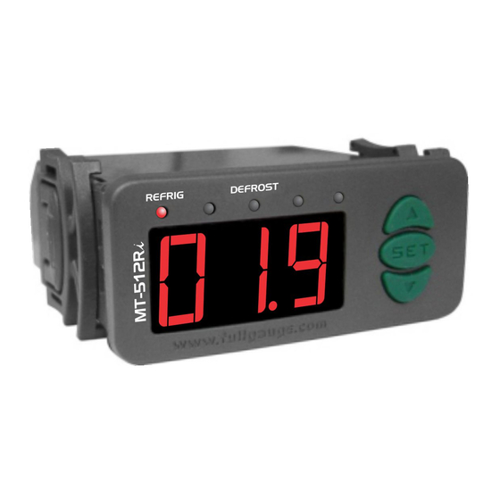
1. DESCRIPTION
The
MT-512Ri LOG
is a temperature controller and indicator, with a joined cyclical timer. Controls
cooling and defrost through compressor shutdowns. It also has an internal datalogger and a serial
output for communication with the SITRAD .
®
Product complies with CE (European Union) and UL Inc. (United States and Canada).
2. APPLICATIONS
• Counters
• Cooled chambers
3. TECHNICAL SPECIFICATION
- Power supply:
MT-512Ri LOG 115 or 230 Vac ±10%(50/60 Hz)
MT-512RiL LOG 12 or 24 Vac/dc
- Control temperature:
-50 to 75.0ºC / -58 to 167°F
- Load current:
NO 16(8)A/250Vac 1HP
NC 8A/250Vac
- Dimensions:
71 x 28 x 71mm
- Operating temperature:
0 to 50 ºC / 32 to 122°F
- Operating humidity:
10 to 90% RH (without condensation)
4. CONFIGURATIONS
4.1 - control temperature adjust (SETPOINT)
- Press
for 2 seconds until appears
SET
The set control temperature will appear.
- Use the
and
keys in order to change the value and, when ready, press
4.2 - Parameters table
Description
Fun
Datalogger operation mode
Indication offset
Minimum setpoint allowed for the end user
Maximum setpoint allowed for the end user
Control differential (hysteresis)
Delay to turn the cooling output on
Cooling time
Defrosting time
Initial state up on energizing the instrument
Indication of the temperature locked during defrost
Delay on the activation of the instrument
Additional time at the end of the first cycle
Datalogger sampling interval
Variation of the temperature to force data recording
Variation of the output force data recording
Memory overwriting
Address of the instrument on the network RS-485
4.3 - Parameters Alteration
-Access function "F01" by simultaneously pressing keys
When the message
appears release the keys and wait for the
indication appears on the display press the
(123) When ready press the
button to confirm.
SET
- Use keys
and
to access the desired function.
- After selecting the function, press
SET
function.
- Use the
and
keys to change the value and, when ready, press
configured value and return to the function menu.
- To exit the menu and return to the normal operation (temperature indication), press
until
appears.
5. FUNCTIONS WITH FACILITATED ACCESS
5.1 - Maximum and minimum temperature logs
Press the
key. The minimum and maximum temperatures registered will appear.
Note:
To restart the logs you just have to keep the
and maximum temperatures until
to be displayed.
MT-512Ri LOG
DIGITAL CONTROLLER FOR COOLING WITH
NATURAL DEFROST THROUGH COMPRESSOR
SHUTDOWN AND INTERNAL DATALOGGER
Ver.08
and then release the key.
to record.
SET
Min
Max
Unit
-
0
2
-5.0 / -9
5.0 / 9
°C / °F
-50 / -58
75.0 / 167
°C / °F
-50 / -58
75.0 / 167
°C / °F
0.1 / 1
20.0 / 40
°C / °F
0
999
sec.
1
999
min.
0
999
min.
0 - cooling
1 - defrost
-
0 - no
1 - yes
-
0
240
min.
0
240
min.
1
999
sec
0 / 0
10.0 / 17
°C / °F
0
1
-
0 - no
1 - yes
-
001
247
-
and
for 2 seconds.
indication. When the
key and use
and
to enter the access code
SET
(press once quickly) to view the value configured for that
to memorize the
SET
key pressed during the viewing of the minimum
5.2 - Manual datalogger activation
Y
ou can turn the internal
for
10
seconds The
and
(datalogger
messages
5.3 - Clearing datalogger memory:
Press the
don't want to clear the memory press
press
SET
5.4 - Viewing current date and time:
You can press the
current day, month, year, hours and minutes, in this order:
Ex: 03/17/2006 12h43min
5.5 - Manual defrost:
- To change from "cooling" to "defrost" or vice-versa, irrespective of the programming, hold
for four seconds, until
To visualize the status and the elapsed time, press
6. SIGNALLING
REFRIG
- Cooling output on
DEFROST
- Performing natural defrost
- Sensor disconnected or temperature out of the specified range.
Default
7. SELECTION OF THE UNIT (Cº / Fº)
2
In order to define the unit that the instrument will operate in, enter function "F01" with the access code
0 / 0
"231" and confirm with the
-50.0 / -58
to choose between
75.0 / 167
SET
appear, and the instrument will return to the function "F01". Every time that the unit is changed, the
1.0 / 2
20
parameters should be reconfigured, since they assume the "standard" values.
240
30
8. WIRING DIAGRAN
0 - cooling
0 - no
0
1
2
3
0
30
A
B
0 / 0
0
1 - yes
1
To the terminal
the distribution box
MT-512Ri LOG MT-512RiL LOG
7 - 8
7 - 9
Note: The length of the sensor cable may be increased by the user up to 200 meters, using a 2 x 24AWG
cable. For immersion in water, use thermometric well.
Integrating Controllers, RS-485 Serial Interface and Computer
(hold it in)
SET
A
A
B
B
A B
Instrument
Distribution Box
Used to connect more than one instrument to the Interface. The wire's connections must
be made in agreement with the following rules: terminal of the instrument connects to
the terminal of the distribution box, that must be connected with the terminal of the
A
Interface. Repeat the action for terminals and
The terminal
of distribution box must be connected to the respective terminals
each instrument.
temperature data
recording
(datalogger)
.
message is displayed followed by the message
). If the parameter F15 is configured with the values
or
will be displayed accordingly.
and
keys for 4 seconds to display
SET
. To clear the memory press
SET
to confirm and exit the function.
key shortly to view the date and time set in the controller. The display shows the
SET
Day
Month
Year
Hours
or
appears in the display.
.
Initial delay
Refrigeration
key. Press the
key and the indication
SET
or
and confirm. After selecting the unit the
REFRIG
4
5
6
7
8
9
10 11 12
0
115 V~
230 V~
(12 V~)
(24 V~)
Load
Power
supply
Load
supply
Above the current specified
of
use contactor
115V
12V
230V
24V
®
RS-485 Network
A
A
A
A
A
A
B
B
B
B
B
B
A B
A B
A B
External
mesh
B
A
B
A
B
A
A
A
B
, being
the cable shield.
ON or OFF by pressing
or
(datalogger
or
the
. The display shows
. If you
until
is displayed and
key in
Defrosting
will appear. Press
message will
Dimension of the clipping for
setting of the instrument
in panel
72 mm
Serial interface
RS-485 Network
RS-485
Full Gauge
A
A
B
B
A B
A B
terminal
grounded
MOD 64
RS-485 Serial Interface
Device used to establish the
of
connection Full Gauge Controls'
®
instruments with the Sitrad
.
)
Advertisement

Related Manuals for Full Gauge MT-512Ri LOG


Summary of Contents for Full Gauge MT-512Ri LOG
- Page 1 The display shows the - Power supply: MT-512Ri LOG 115 or 230 Vac ±10%(50/60 Hz) current day, month, year, hours and minutes, in this order: MT-512RiL LOG 12 or 24 Vac/dc...
- Page 2 IMPORTANT PROTECTIVE VINYL: According to the chapters of norm IEC 60364: Install protector against overvoltage on the power supply. This adhesive vinyl (included inside the packing) protects the instruments against Sensor cables and signal cables of the computer may be joined, but not in the same electric conduit water drippings, as in commercial refrigerators, for example.
Need help?
Do you have a question about the MT-512Ri LOG and is the answer not in the manual?
Questions and answers