Advertisement
Quick Links
Have this manual to hands when
using the FG Finder application.
1. DESCRIPTION
e
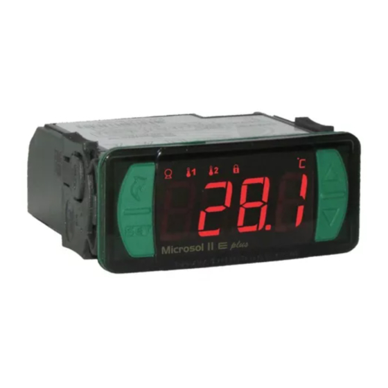
The MICROSOL II
plus is a differential temperature controller for solar heating systems, that
simplifies water temperature management in thermal tanks and swimming pools, using solar power
effectively. It has functions that avoid water from overheating or freezing within the piping. It controls the
water circulation pump based on the differential temperatures between the solar panels and the thermal
tank or swimming pool. It has two outputs for backup heating, that can be electric, gas, diesel-fuelled, or
to program the filtering of the swimming pool. The output AUX2 can also be used to program pool
filtration or as a thermostat for water circulation in the keg so the hot water takes less time to reach the
consumption point, thus wasting less water. In addition, it has a real time scheduling feature that allows
the programming. If a weekly schedule with up to eight daily events. It has RS-485 serial communication
port for Sitrad monitoring and management.
What do auxiliary systems mean (or backup systems)?
They function as backups for the solar heating system on rainy and cold days. They are usually gas
burners, electric heaters, or heat exchangers (heat pump). If the solar heating system is not enough to
heat the water (thermal tank and swimming pool), the auxiliary systems start to operate to heat the
water. Sensor 3 is responsible for the activation of the auxiliary equipment (backup systems).
2. SAFETY RECOMMENDATIONS
- Read this manual before installing and using the controller;
- The installation procedures should be performed by a qualified technician;
- Wear adequate personal protective equipment (PPE);
- Make sure the power supply is switched off and will not be switched on during the installation of the
controller;
- Make sure the controller is properly fastened;
- For application in location subject of water spills, install the vinyl protection provided with the
controller;
- For protection under more critical conditions, we recommend the Ecase cover, available as an option
(sold separately);
3. APLICATIONS
• Pumped solar heating systems
4. TECHNICAL SPECIFICATIONS
Power Supply
Approximate consumption
Temperature range
(**)
Operating temperature
Operating humidity
Maximum current per output
Degree of protection
Dimensions (mm)
Cutout dimensions (mm)
(*) Acceptable variation in relation to the rated voltage.
(**) This device can measure and control temperatures of up to 200°C/392°F, when used in conjunction with a SB59
model silicon sensor cable (sold separately).
IMPORTANT: Only sensors 1 and 2 are included with the product. Sensor 3 may be purchased separately.
5. INDICATIONS AND KEYS
AUX2 output led indication
AUX1 output led indication
PUMP output indication LED
Quick access
menu key (Flatec)
Set key
e plus
Microsol II
Microsol II
DIFFERENTIAL TEMPERATURE CONTROLLER
FOR SOLAR HEATING SYSTEMS WITH TWO
BACKUP STAGES
Functions
Control
Protection
Protection
Temperature
against
against
lock
Functions
differential
Shutdown
freezing
superheating
Microsol II E plus:115 or 230 Vac
±10%
* (50/60 Hz)
Microsol II EL plus:12 or 24 Vdc or Vac
+10%
0.5 VA
Sensor 1 - Panels (or solar collector):
Metal case - Silicon: -50 to 200°C / -58 to 392°F
Sensor 2 - Swimming pool (or thermal tank):
Plastic case - PVC: -50 to 105°C / -58 to 221°F
Sensor 3 -
Auxiliary equipment activation (backup systems):
Plastic case - PVC: -50 to 105°C / -58 to 221°F
0 to 50 ºC / 32 to 122°F
10 to 90% UR (no condensation)
PUMP: 12(8)A / 240Vac 1HP
AUX 1: 10A / 240Vac 2400W
AUX 2: 5(3)A / 240Vac
IP 65 (frontal)
76 x 34 x 77 mm (WxHxD)
X = 71±0,5 Y = 29±0,5 (see Image V)
Functions lock indication LED
Control functions switched off indication LED
Temperature unit indication LED
e plus
IP 65
FRONT
Supervisory
Serial
Degree of
system
programming
protection
6. CONNECTION DIAGRAM
6.1. Electric connections (see images I to IV)
SITRAD
A
B
5 6 7 8
1
2 3 4
D1
SITRAD
A
B
5 6 7 8
1
2 3 4
D1
SITRAD
A
B
5 6 7 8
1
2 3 4
D1
SITRAD
A
B
*
5 6 7 8
1
2 3 4
D1
CAPTION:
To the terminal of the connection block
SENSOR IDENTIFICATION:
S1: Solar panels
S2: Tank / swimming pool
S3*: Surface
Electric noise suppressor filter (sold separately)
Diagram showing the connection of
suppressors in contactors
A1 and A2 are the terminals of the contactor's
coil.
6.2. Temperature sensor connection
- Connect the wires of Sensor S1 to terminals "7 and 8" / Sensor S2 to terminals "1 and 2": the polarity is
indifferent and if Sensor S3 is used, it must be connected to terminals "1 and 3".
- Sensors cables lenght can be extended up to 200 meters using a PP 2 x 24 AWG cable.
- For water immersion use a thermowell (image VI-item 15), available from the Full Gauge Controls
Increase key
product line (sold separately).
6.3. Controller power supply
Decrease key
Use the terminals according to the table below, depending on the version of the controller:
Bornes
9 e 10
9 e 11
e
e
plu s
plu s
M icr os ol II
M icr os ol II
Image I:
Microsol II E plus - 115Vac
9 10 11 12 13 14 15 16 17
Image II:
Microsol II E plus - 230 Vac
9 10 11 12 13 14 15 16 17
Image III:
Microsol II EL plus - 12Vac/dc
9 10 11 12 13 14 15 16 17
12 Vac/dc
Image IV:
Microsol II EL plus - 24Vac/dc
9 10 11 12 13 14 15 16 17
24 Vac/dc
IMPORTANT
EVOLUTION LINE INSTRUMENTS HAVE TWO
DIFFERENT TERMINAL SIZES, BUT BOTH ARE
COMPATIBLE WITH THE 2.0 mm SCREWDRIVER. USE
APPROPRIATE TOOLS DURING INSTALLATION AND
ENSURE A LONGER LIFE AND THE PROPER
OPERATION OF THE PRODUCTS.
Diagram showing the connection of
suppressors in direct drive loads
For the direct drive, consider the specified
maximum current.
A1
A2
Microsol II E plus
115 Vac
230 Vac
evolution
115 Vac
230 Vac
Power supply
Power supply
Load
Microsol II EL plus
12 Vac/dc
24 Vac/dc
Advertisement

Related Manuals for Full Gauge Microsol II E plus


Summary of Contents for Full Gauge Microsol II E plus
- Page 1 Sensor S3 is used, it must be connected to terminals "1 and 3". - Sensors cables lenght can be extended up to 200 meters using a PP 2 x 24 AWG cable. - For water immersion use a thermowell (image VI-item 15), available from the Full Gauge Controls Quick access Increase key product line (sold separately).
-
Page 2: Basic Operations
6.4. NBR5410 and IEC60364 standard recommendations Quick touch: enter the quick access menu. a) Install voltage overload protection in the power supply line of the controller. Held down for 5 seconds: control functions shutdown. b) Install surge protectors-suppressor filter (RC type) - in the circuit to improves instruments performance. -
Page 3: Advanced Operations
The Vacation function is used to switch the backup systems off and to allow cooling of the tank through IMPORTANT: the solar panel when its temperature is below the tank temperature, for example: during the night. The controller has an auxiliary internal power supply to keep the clock running for at least 72 hours in During periods with low or no hot water consumption and high solar intensity, for example vacations, case of power failure. - Page 4 When sensor 1 (panel) is at 35° C and sensor 2 (tank or pool) is at 23° C, the difference will be 12º C. 10.6 Parameter Table Thus the circulation pump will be on (35-23 = 12 greater than 8). With the pump on, the warm water CELSIUS (°C) FAHRENHEIT (°F) circulates down and the cold water circulates up.
- Page 5 F15 - Backup 1 operating mode: F28 - Cyclical timer off time / Intervals* between scans: [,,,0]Backup 1 working independently from backup 2. It allows the adjustment of the time for which the controller will remain with output AUX 2 off when [,,,1]Backup 1 disabled when backup 2 is active.
- Page 6 Device used to establish the the procedure for terminals B and , with being the cable mesh (optional ground). connection of Full Gauge Controls NOTE: The terminal of the connection block is not connected in this instrument. ® F42 - Time for functions lock: instruments with Sitrad .
- Page 7 ENVIRONMENTAL INFORMATION Packaging: Image V Image VI The materials used in the packaging of Full Gauge products are 100% recyclable. Try to perform disposal through specialized recyclers. Product: The components used in Full Gauge controllers can be recycled and reused if disassembled by specialized companies.
Need help?
Do you have a question about the Microsol II E plus and is the answer not in the manual?
Questions and answers