Advertisement
Quick Links
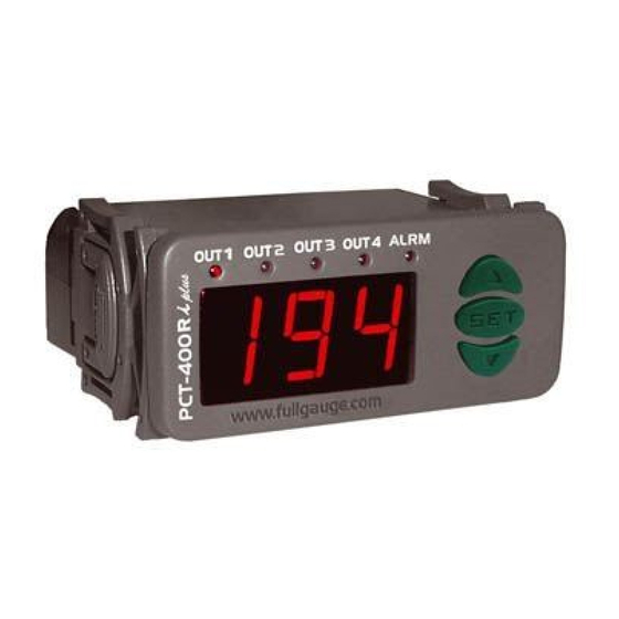
1. DESCRIPTION
PCT-400Ri plus
The
is a pressure controller to be used in cooling centers that need control over
the suction and discharge stages. Working in pairs, it is possible to control up to four fans and four
compressors at the same time. Through remote communication between suction and discharge
controllers, it is possible to obtain more precise control of the process.
Available in the version for high (discharge) and low (suction) pressures, the
operate in conjunction with another, or on its own.
With four pressure control outputs and remote communication, the
discharge pressure gauge to turn off the suction pressure gauge due to an alarm situation. Because it is
very versatile, it management the activation of the charges linearly, by rotation or by capacities. Through
serial output, the RS-485 allows communication with
simple and fast.
2. APPLICATION
For use with refrigeration processes controlling the system's compressors (suction) or fans (discharge).
3. TECHNICAL SPECIFICATIONS
- Power supply:
12Vac/dc (with external energy source 127/220Vac ±10% (50/60Hz))
- Control pressure:
0 to 100 psi / 0 to 6.9 bar (using the SB69-100V transducer)
0 to 500 psi / 0 to 34.4bar (using the SB69-500V transducer)
- Resolution:
1 psi / 0.1bar
- Maximum current:
5(3)A/ 250Vac 1/8HP (each output)
- Dimensions:
71 x 28 x 71mm
- Controller operating temperature:
0 to 50 ºC
- Transducer operating temperature:
-40 to 125°C
- Operating humidity:
10 to 90% RH (without condensation)
- Control outputs:
OUT1 - Output for the first pressure control stage
OUT2 - Output for the second pressure control stage
OUT3 - Output for the third pressure control stage
OUT4 - Output for the fourth pressure control stage
ALRM - Led for indicating alarms
4. CONFIGURATIONS
Attention
At first select the pressure measure unit (item 7) and the kind of pressostat (item 8) that you want to
work. It is very important select it to keep your configuration, if you do not do that the instrument returns
the standard configuration, now it is ready to select the setpoint.
4.1 - Control presssure adjust (SETPOINT)
- Press
for 2 seconds until appears
SET
will appear.
- Use
and
to change the value and then press
4.2 - To enter into the functions menu
Press
and
simultaneously for two seconds until it appears,
appears, press
(short hit) and enter the code (123) through keys
SET
press the key
. Through the keys
SET
manner to adjust them. To leave the menu and return to normal operations, press
appears.
4.3 - Parameters table
Fun
Description
Access code (123)
Indication Offset
-5 / -0.3
Control differential (hysteresis)
1 / 0.1
Minimum Setpoint allowed for the end user
0 / 0.0
Maximum Setpoint allowed for the end user
0
Low pressure alarm
0
High pressure alarm
0 / 0.0
Automatic rearm after alarm
Startup delay (activation)
Time for blocking the alarm
Delay for proving alarm situation
Number of stages
Operating Mode for the Stages
Capacity of the compressor/stage 1
Capacity of the compressor/stage 2
PCT-400Ri plus
DIGITAL PRESSURE CONTROLLER
FOR COOLING CENTERS
Ver.03
PCT-400Ri plus
PCT-400Ri plus
®
SITRAD
software, which makes its configuration
, and release it after that. The adjusted operation pressure
SET
to record it.
then releasing it. When
and
and
access the other functions and proceed in the same
SET
SUCTION
DISCHARGE
Min
Max
Unit
Standard
Min
Max
-99
999
-
0
-99
999
5 / 0.3
psi / bar
0 / 0.0
-20 / -1.4
20 / 1.4
100 / 6.9
psi / bar
4 / 0.4
1 / 0.1
100 / 6.9
100 / 6.9
psi / bar
0 / 0.0
0 / 0.0
500 / 34.4
/ 0.0
100 / 6.9
psi / bar
100 / 6.9
0 / 0.0
500 / 34.4
/ 0.0
100 / 6.9
psi / bar
0 / 0.0
0 / 0.0
500 / 34.4
100 / 6.9
psi / bar
100 / 6.9
0 / 0.0
500 / 34.4
0
4
-
0
0
4
0
999
sec.
0
0
999
0
999
sec.
0
0
999
0
999
sec.
1
0
999
1
4
-
4
1
4
0
2
-
0
0
2
0
100
%
25
0
100
0
100
%
25
0
100
UL-Underwriters Laboratories
Capacity of the compressor/stage 3
Capacity of the compressor/stage 4
Outputs' state when a sensor error is
detected
Minimum time between activation of 2
different stages
can
Minimum time between deactivation 2
different stages
allows the
Minimum time of stage activated
Minimum time of stage deactivated
Maximum operating time between
maintenances on the stage 1
Maximum operating time between
maintenances on the stage 2
Maximum operating time between
maintenances on the stage 3
Maximum operating time between
maintenances on the stage 4
Address of the equipment on the network
RS-485 (serial communication)
4.4 - Parameters description
Access code (123)
This will be necessary for changing the configuration parameters. This code will not be necessary for
only viewing the adjusted parameters.
Indication Offset
Allows compensation for any deviations on the pressure reading resulting from a change of the
sensor.
Control differential (hysteresis)
Is the value of the relative pressure that defines the pressure range within which the control stages
should be activated. The points on which each stage will be activated depend on functions F12
(number of stages) and F13 (operating mode for the stages). The minimum value of the hysteresis is
the number of stages configured in F12.
Minimum Setpoint allowed for the end user
Lower limit, the purpose of which is to avoid any accidental regulation of pressures at levels that are
exaggeratedly below the setpoint.
Maximum Setpoint allowed for the end user
Upper limit, the purpose of which is to avoid any accidental regulation of pressures at levels that are
exaggeratedly above the setpoint.
Low pressure alarm
This is the value of the reference pressure for activating the low pressure signal when below the
desired point.
High pressure alarm
This is the value of the reference pressure for activating the high pressure signal when above the
. To confirm,
desired point. In the event that the pressure gauge is configured as a discharge, a remote high
pressure alarm should also be sent to the suction pressure gauge, so that it deactivates its outputs.
(long hit) until
Automatic rearm after alarm
This function defines how the pressure gauge will behave after the remote alarm situation stops.
Unit
Standard
-
0
psi / bar
0 / 0.0
psi / bar
10 / 0.7
Startup delay (activation)
psi / bar
0 / 0.0
Time counted from the initialization wherein the instrument only shows the pressure without
psi / bar
500 / 34.4
activating either the alarm or the stages.
psi / bar
0 / 0.0
Time for blocking the alarm
psi / bar
500 / 34.4
This is the time that the alarm will remain deactivated, even under alarm conditions. This block time
starts to be counted after the startup delay count has ended (F09).
-
0
sec.
0
Delay for proving alarm situation
sec.
0
Alarm blocking time to distinguish between one of the alarm situations or a transitory condition of the
system.
sec.
1
-
4
Number of stages
Function that indicates which stages will be activated.
-
0
%
25
Operating Mode for the Stages
%
25
Function that selects the method for activating the stages.
pressure of the line moves away from the setpoint. The activation point for each compressor is
calculated in accordance with the value of the hysteresis (F03) and the number of stages
configured (F12).
SUCTION PRESSURE
GAUGE
0
100
0
100
0
15
0
999
0
999
0
999
0
999
0
999
0
999
0
999
0
999
1
247
Only accepts manual rearms, even after remote alarm situations stop
The controller only performs one automatic rearm
The controller only performs two automatic rearms
The controller only performs three automatic rearms
The controller only performs automatic rearms
Linear Mode:
In this mode of operation, the controller activates compressors as the
DISCHARGE PRESSURE
GAUGE
%
25
0
100
%
25
%
25
0
100
%
25
-
0
0
15
-
0
sec.
2
0
999
sec.
2
sec.
1
0
999
sec.
1
sec.
1
0
999
sec.
1
sec.
1
0
999
sec.
1
x10h
999
0
999
x10h
999
x10h
999
0
999
x10h
999
x10h
999
0
999
x10h
999
x10h
999
0
999
x10h
999
-
1
1
247
-
1
Advertisement

Related Manuals for Full Gauge PCT-400R Plus


Summary of Contents for Full Gauge PCT-400R Plus
- Page 1 PCT-400Ri plus DIGITAL PRESSURE CONTROLLER FOR COOLING CENTERS DISCHARGE PRESSURE GAUGE Ver.03 SUCTION PRESSURE GAUGE UL-Underwriters Laboratories 1. DESCRIPTION Capacity of the compressor/stage 3 PCT-400Ri plus is a pressure controller to be used in cooling centers that need control over Capacity of the compressor/stage 4 the suction and discharge stages.
- Page 2 Capacity of the compressor/stage 1 Compressor activation step Step = Hysteresis / Number of stages This function defines the capacity in a percentage of stage 1 in relation to the total of the active stages. Activation pressure of the "N" output Activation = Setpoint + ((N-1) x Step)) Capacity of the compressor/stage 2 For example, if the setpoint is 10psi, the hysteresis is 8psi and the number of stages is 4, the first...
- Page 3 Brown - A Device used to establish the Red - B Alarm Alarm connection Full Gauge Controls’ 5.4 - Restart of the maintenance alarm ® instruments with the Sitrad In the event that any of the maintenance alarms has activated the message with the number of the stage, it will be changed on the display.
Need help?
Do you have a question about the PCT-400R Plus and is the answer not in the manual?
Questions and answers