
Related Manuals for Bently Nevada 3300/01 Series


Summary of Contents for Bently Nevada 3300/01 Series
- Page 1 (217) 352-9330 | Click HERE Find the GE / Bently Nevada 3300/01-01 at our website:...
- Page 2 PART NO. 80175-01 3300/01 SYSTEM MONITOR OPERATION MANUAL BENTLY re\ NEVADA •...
- Page 3 NOTICE READ THE FOLLOWING BEFORE INSTALLING OR OPERATING EQUIPMENT Bently Nevada Corporation has attempted to identify areas of risk created by improper installation and/or operation of this product. These areas of information are noted as WARNING or CAUTION for your protection and for the safe and effective operation of this equipment. Read all instructions before installing or operating this product.
- Page 4 Transient Data Manager User Guide, 79206-01 Allen Bradley Communications Interface Module 1770-KF2 User's Manual Modicon Modbus Protocol Reference Guide PI-MBUS-300 REV B Keyphasor® is a registered trademark of Bently Nevada Corporation Proximitor® is a registered trademark of Bently Nevada Corporation •...
- Page 5 80175-01 System Monitor Blank Page...
-
Page 6: Table Of Contents
80175-01 • System Monitor CONTENTS SECTION TITLE System Monitor Monitor Functions Disassembly Procedure Front Panel Assembly Removal OK Relay Configuration Communications Processor Interface Performance Testing Keyphasor Performance Test -VT Jumper Configuration Recommended Spare Parts Specifications Serial Interface Overview Serial Interface Setup Switch Settings Jumper Settings Cabling... - Page 7 System Monitor Blank Page •...
-
Page 8: System Monitor
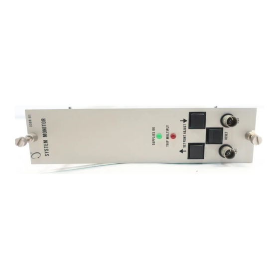
80175-01 • S y s t e m Monitor 1 I SYSTEM MONITOR 3 3 0 0 / 0 i ",r,TE.M M O N I T O R (6(6 6 1_ 0 PR )K M T O R — - L K 0 K 2 _ ( TOP I CAI. - Page 9 1 • System Monitor 80175-01 1 f SYSTEM MONITOR Two types of Power Input Modules (PIM) can be used with the System Monitor. The PIM shown below on the left is supplied when the Serial Interface option is specified. It includes the two additional 25-pin serial connectors.
-
Page 10: Monitor Functions
System Monitor M O N I T O R F U N C T I O N S SYSTEM POWER-UP INHIBIT The System Monitor provides a Power-up Inhibit function that allows each monitor to inhibit its alarms during power-up, or whenever a system supply voltage falls below its operating level. After power-up, the inhibit function remains active for approximately 2 seconds. - Page 11 System Monitor I 2 I MONITOR FUNCTIONS 1 1 0 ALARM SETPOINT ADJUST The System Monitor has two switches on the front panel that adjust alarm setpoint levels on each monitor. One switch is for upscale adjustments and the other is for downscale adjustments. KEYPHASORS The System Monitor receives input from two Keyphasor transducers through terminals o n the power input module and buffers the input for use by the monitors.
-
Page 12: Disassembly Procedure
System Monitor I DISASSEMBLY PROCEDURES ILM M O N I 1 o H u 111 I ILCM k A ( T h 0 0 y, j , S I C ) C U L T _ 6'E, SYSTEM M O N I T O R c: R E M O V E =_,IDE C O v r R B P i N C H I N G P H T H U D I N O ON E A C H CAL , c l i \ N D f l P 4 -... -
Page 13: Front Panel Assembly Removal
I • System Monitor 4 I FRONT PANEL ASSEMBLY REMOVAL Rr FA!NI N I C 3 I D I G L Aril-J[1r F ! P k I Nti: • f r P 5 3 T P ,131-p3 1 7 1 TF- I 7 t h 1 P 9... -
Page 14: Ok Relay Configuration
System Monitor 5 I OK RELAY CONFIGURATION THE F O L L O W I N G D I A G R A M SHOWS T H E F U N C T I O N A L C O N C E P T o r T H E O K R B L A I FOR MOPE D E T A I L _ _ r FR T O S C H F M AT I C ISEE MONI1OR MONITOR... -
Page 15: Communications Processor Interface
System Monitor 6 I COMMUNICATIONS PROCESSOR INTERFACE Communications processor systems used with 3300 systems should all operate from the same power source. If they do not and if the 3300 system power goes off, the computer screen will indicate system OK and displayed meter values will be approximately 7% of full scale. - Page 16 • System Monitor 6 I COMMUNICATIONS PROCESSOR INTERFACE MONITOR/1 MONITOR#2 MONITOR#N *CONNECTIONS T Y P I C A L O N AL:_ MONITORS POSITION ENABLE • BUFFERED D ATA SELECT STATIC D ATA O U T BUFFERED TRANSDUCER CED BUFFERED TRAN'T,DErhE C R 2 BAPKPLANf SYSTEM COMMUNICATION'T,...
-
Page 17: Performance Testing
System Monitor 7 1 PERFORMANCE TESTING !RIP WI !III I t ! ! POINT Afl.PiSl'ir r---1 V r J U M P E EM M O N I T OF< ALJ1) POWER S U P P L M U •`) I B E SETT T O F. A W . VOLTAGE ( - i 8 V D C O R - 2 4 V D C ) O R SYSTEM SUPPLIES OK L E D W I L L N O T G O O N . -
Page 18: Keyphasor Performance Test
• 1 System Monitor 8 I KEYPHASOR PERFORMANCE TEST NOTES: T H E F O L L O W I N G PROCEDURE F O R T E S F I N ( . ; K E - ( P H A S O R 1 I S T Y P I C A L FOR T E S T I N G K E Y P H A S O R 2 2. - Page 19 System Monitor 1 • K E Y P H A S O R P E R F O R M A N C E T E S T D I C O N N E C I W I R E : F R O M K 0 1 P O W E R / N D M E A S U R E V O L T A G E A T POWER I I \ P J T M O D U L E T E R M I N A L .
- Page 20 80175-01 S stem Monitor KEYPHASOR PERFORMANCE TEST RECONNECT WIRE A T KOI POWER TERMINAL. DISCONNECT W I R E A T - V T ( - 1 8 v D C OR - 2 4 V D C ) T E R M I N A L O F PROXIMITOR A N D MEASURE VOLTAGE AT WIRE_ V O LTA G E SHOULD MEET TOLERANCE L I S T E D I N STEP I VOLTAGE OUT O F...
- Page 21 System Monitor 80175-01 P E R F O R M A N C E T E S T 5. C H E C K K E Y P H A S O R O U T P U T S I G N A L A T S Y S T E M M O N I T O R F R O N T PA N E L K01 C O A X I A L 17ONNECTOR.
- Page 22 System Monitor • 1 8 I KEYPHASOR PERFORMANCE TEST D I S C O N N E U T W I P E A T P O W E R I N P U T M O D U L E K O 1 T E R M I N A L A N D C H E O T WIRE F O R ' r \ H Y P N A S O R S I G N A L ONAL 1 - ) f P E E L A G E...
- Page 23 I • System Monitor 8 I KEYPHASOR PERFORMANCE TEST ThJIHL; ' v . / A L A I L , H ( y r M r OP O U T P U T T E R M I N A L A N D C H E I C , ( 2 ; ‘ ; ' ) ; L . A I O U T P U T J A L n e i l n •...
- Page 24 • System Monitor 9 1 -VT JUMPER CONFIGURATION TO CHANGE TRANSDUCER V O LTA G E ( - V T ) O N SYSTEM M O N I TO R . D I S E N G A G E FROM R A C K ( S E E P ] ) A N D S E T J U M P E R A S FOLLOWS: VOLTAGE - V T JUMPER...
- Page 25 System Monitor I • I 1 0 I RECOMMENDED SPARE PARTS DESCRIPTION PART NUMBER System Monitor 3300/01-XX XX .-- 01 without Serial Interface XX -,-- 0 2 with Serial Interface 84030-01 System Monitor PWA 83989-01 Serial Interface PWA System Monitor front panel 78452-01 •...
-
Page 26: Specifications
• 80175-01 System Monitor 11 I SPECIFICATIONS INPUT SUPPLY No external loads, normal operation mode, 25°C Supply Voltage + VRH 22.55 ± 6.05 V d c 11.22 ± 3.09 V d c +VRL +7.5V 7.5 ± 0.1 V d c 5.00 ±... -
Page 27: Serial Interface Overview
System Monitor 80175-01 SERIAL INTERFACE OVERVIEW PROTOCOLS The 3300 Serial Interface option gives the 3300 system communication capability using either RS- 232C or RS-422A connections. The interface implements two standard protocols which are switch selectable on the interface. The protocols are Modicon Modbus and Allen Bradley full duplex (DF1). Each protocol possesses its own unique characteristics but the data which is transferred over each interface link is similar. - Page 28 • System Monitor 80175-01 SERIAL INTERFACE OVERVIEW discussion of the message content and other related protocol details refer to the documents listed in the forward of this manual. The Serial Interface is designed to operate concurrently with either Transient Data Manager (TDM) or Dynamic Data Manager (DDM).
-
Page 29: Serial Interface Setup
• System Monitor 80175-01 SERIAL INTERFACE SETUP Proper operation o f the Serial Interface requires that the switch and jumper settings b e set appropriate for both the configuration of the 3300 rack(s) and the style of communications between the host device and the Serial Interface. Once these settings and the proper cable connections are made, the interface can receive command messages and return response messages to a host device. -
Page 30: Switch Settings
• System Monitor 80175-01 13 I SERIAL INTERFACE SETUP SWITCH SETTINGS Three 8-position switch assemblies are located in the upper left corner of the Serial Interface option PWA. SE I T H E ADDRESS I N A . 0 1 4 . S W I T C H c o p R E s p o r n u „ '1':) A I S T A T E . -
Page 31: Jumper Settings
• System Monitor 80175-01 13 I SERIAL INTERFACE SETUP JUMPER SETTINGS Several j u m p e r s a r e l o c a t e d o n t h e S e r i a l `,FT T H I S C O N F I N N R AT I O N w H F N N S I N T Interface option PWA. - Page 32 • 80175-01 System Monitor CABLING CABLE CONNECTION TO ALLEN BRADLEY 1770-KF2 COMMUNICATIONS MODULE The 1770-KF2 is a stand-alone communication interface which provides a RS-232C or RS-422A link between asynchronous devices and an Allen Bradley Data Highway or Data Highway Plus communications network.
-
Page 33: Cabling
• System Monitor 80175-01 CABLING CABLE CONNECTION TO ALLEN BRADLEY 1771-KE OR 1785-KE COMMUNICATIONS MODULES Both the 1771-KE and the 1785-KE are designed to be installed in an I/O chassis. A 1771-KE provides an interface between a RS-232C communication link and an Allen Bradley Data Highway Communication link. - Page 34 • 80175-01 System Monitor 1 1 4 I CABLING CABLE CONNECTION TO HONEYWELL PLC GATEWAY (PLCG) OR HONEYWELL DATA HIGHWAY PORT (DHP-II) The Honeywell PLCG provides an interface between RS-232C devices using Modicon Modbus protocol and the TDC 3000 Local Control Network (LCN). The DHP-II provides a similar interface to the Honeywell Data Highway.
-
Page 35: Cable Diagrams
• System Monitor 80175-01 CABLE DIAGRAMS 8 4 I ) R A C K r),ARL I' FM E • ( RAO) (7;01411:C ND— 1.1.(5ATIECTON. • • • PE-MAL HC, ) •... - Page 36 • 80175-01 System Monitor CABLE DIAGRAMS ViHT 20 - - - - 8 4 9 1 7 1 R - 4 2 2 H O S T C A H L E • FEMALE • 85.34'3 P S 2 3 2 H O S T C A B L E MALE FEMALE •...
-
Page 37: 6 . P R O T O C O L Specifications
System Monitor 80175-01 16 I PROTOCOL SPECIFICATIONS ALLEN BRADLEY PROTOCOL MESSAGE TYPES For a complete description of the Allen Bradley message formats refer to the Allen Bradley protocol document listed in the forward. The messages that may be transmitted and received by the Serial Interface will be selected from the Allen Bradley basic command set. - Page 38 • 80175-01 System Monitor 16 IL PROTOCOL SPECIFICATIONS change to settle. 4. 16-bit counter of the number of times a communications overrun has occurred. The counters will be returned in the response message in the above order. The request message will set the ADDR field to 0 and the SIZE field to 8.
-
Page 39: Data Addressing
System Monitor 80175-01 PROTOCOL SPECIFICATIONS ALLEN BRADLEY PROTOCOL DATA ADDRESSING The Serial Interface uses fixed protocol addresses for the starting locations of rack data. These addresses are n o t the physical addresses o f the data in the interface memory. They are the addresses used in the protocol messages to access data which is available from the interface. - Page 40 80175-01 • S y s t e m Monitor PROTOCOL SPECIFICATIONS configuration of the rack is known, then the exact locations of all the rack's direct values can be specified. A simple formula which can be used to calculate the starting address of monitor direct values is Starting address = 8 + 2(monitor slot number - 1) + 2(number of 6-channel temperature monitors to the left of the selected monitor)
- Page 41 System Monitor 80175-01 1 1 6 PROTOCOL SPECIFICATIONS temperature for channel 1. Channels 2 through 6 follow at addresses 19 through 23. The Allen Bradley command format will have the ADDR field set to 36 and the SIZE field set to 12.
- Page 42 • 80175-01 System Monitor PROTOCOL SPECIFICATIONS host. The Allen Bradley command format will have the ADDR field set to 96 and the SIZE field set to 18. See note 2 at beginning of Allen Bradley Protocol Data Addressing. Example 2: Read monitor status from a 6-channel monitor in slot 7.
-
Page 43: Data Format
System Monitor 80175-01 PROTOCOL SPECIFICATIONS ALLEN BRADLEY PROTOCOL DATA FORMAT Internally the Serial Interface converts the backplane multiplexed static data signal into a digital value using an 8-bit analog-to-digital convertor. When an analog data request message is received on Allen Bradley full duplex protocol, this 8-bit value is shifted left four bits to represent a 12-bit value. - Page 44 • 80175-01 System Monitor 16 I PROTOCOL SPECIFICATIONS ALLEN BRADLEY PROTOCOL EXCEPTION RESPONSES Error codes will be returned in the response message when the interface receives a message with an illegal function, address, or data range. Error codes returned in the message are Allen Bradley type REMOTE error codes.
- Page 45 System Monitor PROTOCOL SPECIFICATIONS MODBUS PROTOCOL MESSAGE TYPES A Serial Interface in a Modbus protocol connection will behave as a slave only. The mode of transmission is RTU. The messages that will be allowed to be received and transmitted by the Serial Interface are as follows: Message Function Code...
- Page 46 • 80175-01 System Monitor PROTOCOL SPECIFICATIONS LOOPBACK/MAINTENANCE This message allows multiple functions depending on the diagnostic code which is imbedded in the request message. Diagnostic Code Meaning Return query data (2 bytes) Return diagnostic register Clear counters and diagnostic register Return message count Return communications error count Return exception count...
- Page 47 System Monitor 80175-01 PROTOCOL SPECIFICATIONS MODBUS PROTOCOL DATA ADDRESSING The Serial Interface uses fixed protocol addresses for the starting locations of rack data. These addresses are n o t the physical addresses o f the data in the interface memory. They are the addresses used in the protocol messages to access data which is available from the interface.
- Page 48 • 80175-01 System Monitor I 1 6 I PROTOCOL SPECIFICATIONS Example 1: Retrieve the direct values from a 3300 rack which contains a vibration monitor in slot 4 and a 6-channel temperature monitor in slot 5. The vibration monitor has two values associated with it, channel one vibration and channel two vibration.
- Page 49 • System Monitor 80175-01 PROTOCOL SPECIFICATIONS MONITOR STATUS The monitor status indicators have a value of 1 o r 0. Each monitor will have these three status values associated with it: Alert, Danger and not OK. Individual channel status is not available. If any channel of a monitor is in alert, then the monitor status is Alert.
- Page 50 • 80175-01 System Monitor PROTOCOL SPECIFICATIONS Example 2: Read monitor status from a 6-channel temperature monitor in slot 7. The rack also has a 6-channel temperature monitor in slot 1, with slots 3, 4, 5 and 6 empty. Starting address (point number) = 3(5) = 15. Note that slot 2 is not considered an empty slot because it is occupied by the double wide 6-channel monitor.
- Page 51 System Monitor 80175-01 PROTOCOL SPECIFICATIONS MODBUS PROTOCOL DATA FORMAT Internally the Serial Interface converts the backplane multiplexed static data signal into a digital value using an 8-bit analog-to-digital convertor. When an analog data request message is received on Modbus protocol, this 8-bit value is shifted left 4 bits to represent a 12-bit value. Since the maximum value the 8-bit convertor can have is 255, then the maximum 12-bit value is 255(16) = 4080.
- Page 52 • 80175-01 System Monitor PROTOCOL SPECIFICATIONS MODBUS PROTOCOL EXCEPTION RESPONSES Error codes will be returned in the response message when the interface receives a message with an illegal function, address, or data range. Exception Code Exception Condition illegal function in request message Illegal data address in request message Illegal data range in request message Example:...
-
Page 53: Exception Responses
• System Monitor 80175-01 PROTOCOL SPECIFICATIONS MODBUS PROTOCOL DIAGNOSTIC COUNTERS There are four diagnostic counters and one diagnostic register which are maintained by the Serial Interface when implementing the Modbus protocol. Each of these counters and the diagnostic register may be accessed via the Loopback/Maintenance function code 8. Access counter by using Counter Name What gets counted... - Page 54 80175-01 • System Monitor 16 I PROTOCOL SPECIFICATIONS DIAGNOSTIC REGISTER The diagnostic register is a status word that is maintained by the Serial Interface and is returned in response to a function code 8, diagnostic code 2 command. Failure of self tests will cause bits to be set in the diagnostic register.
-
Page 55: Scan Rates
System Monitor 80175-01 PROTOCOL SPECIFICATIONS BACKPLANE DATA SCAN RATES ACTIVE MODE When there is no Communications Processor connected to the monitor rack, the Serial Interface must control scanning o f the 3300 rack backplane t o acquire direct and status values. When operating in this mode the interface data base is completely updated for an entire rack in 120 msec. -
Page 56: Modem Controls
• 80175-01 System Monitor PROTOCOL SPECIFICATIONS MODEM CONTROLS The following definitions apply to the RS-232C signals as implemented by the Serial Interface. The modem control signals DTR, DSR, DCD, RTS and CTS are active only if the MDEM switch (SW2) on the Serial Interface circuit board is set ON. -
Page 57: Self Test
System Monitor 80175-01 SELF TEST The Serial Interface performs the following internal self tests on power-up: Rom Check A checksum calculation is performed on the rom memory. The value obtained is compared with a previously calculated value stored in memory. If the values do not compare, an error flag is set and bit 0 of the Diagnostic Register is set. -
Page 58: Schematics And Drawings
• 80175-01 System Monitor SCHEMATICS AND DRAWINGS • •... - Page 59 • Z 5 s ° 3 E a , ± 1 • • SERIAL INTERFACE SCHEMATIC SHEET 1 OF 4...
- Page 60 E N . C I 100K PLOP %PIT 1 U 5 PEov 100K U 2 5 " . . ° 1,re-411 5 C I R = , :111150-Ei 00695060 6 c i • - .owF I l F MURES r U P I •...
- Page 61 • • • Pg • • 4 2 5 . ix4.5 2200UF , - . I C 0.585sx „ ± 1 . _ C2 10Git 4•7"-F - 1 - 1 0 0 L F 0 0 2 VFEF , 9 5 . •1 S C / T C D .
- Page 62 • ? . 1 P .. • , T 7 : 1 • SERIAL INTERFACE SCHEMATIC SHEET 4 OF 4...
- Page 63 • ( 7 : 7 ' 7 1 7 0 - _ c,117.1[A 1/2 E)-(, � 0 0 0 0 0 0 0 0 0 0 0 0 0 0 0 0 0 0 0 0 0 0 0 0 0 n „00.0 o P , 1 1 1 14...
- Page 64 •...
- Page 65 REFERENCE DE5IGAATOE51 UOL - A G E C H A R T LAST USED N O T USED I C 5 8 C 5 3 , 5 4 CCOM C R 2 I ..8k., 1.25,26 ,ZIR k.42 ACOM T P 1 7 T P 4 . 1 0 . 1 6 1 4 7 , 1 7 , 4 , 6 , 5 °CCM J 4 .
- Page 66 • • • S U P P L Y C H E C K C I R C U I T S TP15 VQ L . 2 9 42.511 .011. F---<72, V I E D 0312 R E C I S 1 ' 4 5 3 2 C 6 b R 1 1Y101 v O u...
- Page 67 • SYSTEM MONITOR SCHEMATIC SHEET 3 OF 6...
- Page 68 • • • L O A - A 0 3 E N A B L E D 0 0 t t M O N I T O R S E L E C T 0 . 0 4 . 3 U 1 7 L O B - R E S E T 5 8 4...
- Page 69 '9%\i‘v 6 . 5 K .001 MC33172 K 6 1 0 11 3 K 2 7 0 ' 6 C 7 1/29, S H T 5 C O R I 5 2 24 9 K + 7 . 5 4 - - - 1 ( 1 1 , .
- Page 70 —VT M C 3 3 1 7 2 M P F 9 6 0 1.3K 1/4W R159 A J \ A , \ . , \ N 249K 1/414 R7E1 1>. —I— C24 S Y S T E M M O N I T O R S C H E M A T I C S H E E T 5 O F 6 •...
- Page 71 n Z n q r j ( j ) k 44 t 4 y i " 1 - t r u. v , 0 1 s i n a i r o bbtx_*5.1.*E.0.01b00450r 070 0 5 . 1 0 . L I N O W W O d J S I n d N i s i n ) s l i t w i n s •...
- Page 72 • nwn o•10.30 0 1 I i n I )10 i f ] ] W [II --1M o of -4 - I El „ A ' 0 7,31 I L i d 0 0 0 0 0 0 0 0 0 0 0 0 0 0 0 0 0 0 0 T .1...
- Page 73 • •...
- Page 74 System Monitor • INDEX -18V Option -24V Option 1770-KF2 1771-KE 1785-KE Active Mode ALARM SETPOINT ADJUST Backward compatible Baud rate Binary coded decimal Binary state Block character check BUS BUFFER Byte addresses Checksum CLEAR TO SEND Coaxial connectors Command code 1 33, 34 •...
-
Page 75: Indexi
System Monitor INDEX • DIAGNOSTIC COUNTERS DIAGNOSTIC COUNTERS RESET DIAGNOSTIC LOOP DIAGNOSTIC READ DIAGNOSTIC REGISTER DIAGNOSTIC STATUS Digital common Direct 31, 32, 40 Distributed Control Systems Double-wide Dynamic Data Manager ENVIRONMENTAL Error codes EXCEPTION RESPONSES Firmware revision Full duplex Function Code 4 Function code 8 •... - Page 76 • 80175-01 ystem Monitor INDEX 31, 39 Minor Rev Number Modem MODEM CONTROLS Octal OK led OK RELAY On-line Operating Temperature Parity Passive Mode PLCG Position select 3, 19, 50 POWER-UP Priority Programmable controller Protocol mode Ram Check 38, 40 READ INPUT REGISTER 38, 42 READ INPUT STATUS...
- Page 77 System Monitor • SUPPLY VOLTAGES OK System Reset TDC 3000 Terminate Transient Data Manager TRANSMITTED DATA TRIP MULTIPLY UNPROTECTED READ Unprotected Read Command Unstable Word Word address • • Index-4...
Need help?
Do you have a question about the 3300/01 Series and is the answer not in the manual?
Questions and answers