Table of Contents
Advertisement
Quick Links
Advertisement
Chapters
Table of Contents

Related Manuals for Bently Nevada 3300/48


Summary of Contents for Bently Nevada 3300/48
- Page 1 Artisan Technology Group is your source for quality new and certified-used/pre-owned equipment SERVICE CENTER REPAIRS WE BUY USED EQUIPMENT • FAST SHIPPING AND DELIVERY Experienced engineers and technicians on staff Sell your excess, underutilized, and idle used equipment at our full-service, in-house repair center We also offer credit for buy-backs and trade-ins •...
- Page 2 • PART NO. 84417-01 3300148 CASE EXPANSION MONITOR • OPERATION MANUAL BENTLY 1• • • • NEVADA • 1 • r i 1 1 4 2 : ; 1 0 1 " 3 1 .
- Page 3 NOTICE READ THE FOLLOWING BEFORE INSTALLJNG OR OPERATING EQUIPMENT Bently Nevada Corporation has attempted to identify areas of risk created by improper installation and/or operation of this product. These areas of information are noted as WARNING or CAUTION for your protection and for the safe and effective operation of this equipment. Read all instructions before installing or operating this product.
- Page 4 3300/01 System Monitor, 80175 3300/48 Case Expansion Maintenance, 84418-01 Dynamic Data Manager System, 46390-01 Keyphasore is a registered trademark of Bently Nevada Corporation • Proximitor4 is a registered trademark of Bently Nevada Corporation Document No. 84417 • First Printing: April 1989 • Revision NC: April 1989...
- Page 5 • 84417-01 Expansion Monitor Operation • Blank Page •...
-
Page 6: Table Of Contents
• 84418-01 Case Expansion Monitor Maintenance CONTENTS TITLE SECTION Case Expansion Monitor System Monitor Options 3. P r o g r a m m a b l e options 4. M o n i t o r Functions 6. B y p a s s 7. - Page 7 • Case Expansion Monitor Operation 84417-01 • Blank Page...
- Page 8 • Case Expansion Monitor Operation 84417-01 I 1 I C A S E EXPANSION MONITOR SYSTEM SIGNAL I N P U T RELAY MODULE LOCATION 4F,r-• 4.-14 -4r4 i rili 4 - 44 • IA 4 4 ° 4 1 I 41,.
-
Page 9: Monitor Options
MONITOR PART NUMBER TRANSDUCER FULL SCALE RANGE I N P U T A L A R M RELAY A P P R O V A L 3300/48 00 = NOT REQUIRED 01 = 1 inch LVDT 00 = NONE 01 = 0 - 1.0 inches... -
Page 10: P R O G R A M M A B L E Options
• 84417-01 Case Expansion Monitor Operation I 3 I PROGRAMMABLE OPTIONS M o n i t o r Feature Option Monitor Feature Option Latching Enabled * Danger Mode First Out Non-Latching Disabled Alarm Delays 0.1 sec +4 to +20 mA * 1 s e c Recorder Output +1 to + 5 Vdc... -
Page 11: Monitor Functions
• 84417-01 Case Expansion Monitor Operation MONITOR FUNCTIONS CASE EXPANSION - The Case Expansion ALARM - Since alarms for the case expansion Monitor continuously monitors the expansion monitor use differential values, alarm setpoints of the machine case o n both sides o f a may b e read when the monitor i s in the machine. - Page 12 • 84417-01 Case Expansion Monitor Operation MONITOR FUNCTIONS [CONT] The User-Invoked test performs a power-up BUFFERED OUTPUT - The Case Expansion self test and allows error messages stored Monitor provides the buffered output from the LVDTs at two locations: a t the coaxial cable during cyclic tests to be read and cleared.
- Page 13 • 84417-01 Case Expansion Monitor Operation 1 5 1 O K A • — op( — O D N O DIRECT 0 O A L R D I F F 0 0-9YRASS--0 Note: Since each channel in the system controls the OK Relay, either channel can cause a Not OK Relay conditon (de-energized relay).
-
Page 14: Bypass
• 84417-01 Case Expansion Monitor Operation 6 I BYPASS A O - - C R — O 8 00140 DIRECT 0 O A L R DUFF 0 0 —BYP ASS—. LED DISPLAY CONDITION • Monitor in DANGER BYPASS MODE • BYPASS •... -
Page 15: Alert And Danger
• 84417-01 Case Expansion Monitor Operation ALERT AND DANGER 7 . N Danger A O—OK— O B — OK . - - - 1 1 1 1 0 . 0 D N G DI R ECT 0 O D N G DI R ECT 0 A l e r t Q A L R D I F R 0 O A L R D I F F 0... -
Page 16: R E A D Direct And Differential Mode
• 84417-01 Case Expansion Monitor Operation jmn3 j R E A D DIRECT OR DIFFERENTIAL MODE e3340 / 4 0 3 3 0 0 / 4 4 1 C A S E EXPANSION C A S E EXP ANSION MONI T OR MCNI T OR 0 . - Page 17 Note: Yo u can read the setpoints in Differential Mode only. I f you try to read the setpoints in direct mode, the display will be blank. Alert SetPoint = 0.4 inches D a n g e r SetPoint = 0.6 inches • 3300/4e 3300/48 CASE EXPANSION CASE EXPANSION MONITOR MONITOR...
- Page 18 • Case Expansion Monitor Operation 84417-01 SELF TESTS The three levels of self tests are power-up - performed only when the monitor is turned on cyclic - continuously performed by the monitor user-invoked - performed only when initiated by the user. 3 3 0 0 / 4 8 The monitor on this page is giving a signal that CASE EXPANSION...
- Page 19 84417-01 Case Expansion Monitor Operation I 1 0 I S E L F TESTS Follow these steps to read the error codes that have been stored in the monitor: ((,€ 3 3 0 0 / 4 6 C A S E EXP ANSION M O N I T O R mmlimmor .71c.
- Page 20 • Case Expansion Monitor Operation 84417-01 SELF TESTS 3 00/4f €i ? 1 3300/41 CASE EXPANSION CASE EXPANSION MONITOR MONITOR m o i m m a r r = - 1 = . e E "7= = E • E X ;...
- Page 21 • 84417-01 Case Expansion Monitor Operation 1 . 2 . 1 S E L F TESTS e33os,41 C A S E EXP ANSION M O N I T O R 0 - - OK - - 0 Q o m D i FecTO OAut D i FFO •...
- Page 22 Case Expansion Monitor Operation 84417-01 SELF TESTS Error Code Description ROM CHECKSUM has failed. * e 3 3 0 0 / 4 8 EEPROM failure number 1. C A S E EXPANSION MONI T OR vommmimor 4 E E P R O M failure number 2. * * * Adjust set points =.
-
Page 23: Index
84417-01 Case Expansion Monitor Operation INDEX Alarm Alarm Relays Alert 4, 8 4, 8 Danger Levels of Alarm Alarm Delays Buffered Output Bypass 7, 11 Danger Bypass Errors Continuing Errors Description of Error Codes Error Code ... . - Page 24 84417-01 • Case Expansion Monitor Operation INDEX Self Tests 5, 6, 11, 15 Cyclic 5, 11 Power-up 5 , 7, 11, 12 User-Invoked Self Test Pins 11, 15 Setpoint Signal Input Relay Module Transducer Linear variable differential transducers Transducer input options Upscale Direction •...
- Page 25 • • •...
- Page 26 • PART NO. 84418-01 3300/48 CASE EXPANSION MONITOR • MAINTENANCE MANUAL BENTLY • • • • • • NEVADA • e r ..r • P . • • I • • • 0 • •...
- Page 27 NOTICE READ THE FOLLOWING BEFORE INSTALLING OR OPERATING EQUIPMENT Bently Nevada Corporation has attempted to identify areas of risk created by improper installation and/or operation of this product. These areas of information are noted as WARNING or CAUTION for your protection and for the safe and effective operation of this equipment. Read all instructions before installing or operating this product.
- Page 28 3300/01 System Monitor, 80175 3300/48 Case Expansion Operation, 84417-01 Dynamic Data Manager System, 46390-01 Keyphasor® is a registered trademark of Bently Nevada Corporation • Proximitor® is a registered trademark of Bently Nevada Corporation Document No. 84418 F i r s t Printing: April 1989 si Revision A: December 1989 Copyright©...
- Page 29 Case Expansion Monitor Maintenance Blank Page...
- Page 30 • 84417-01 Case Expansion Monitor Operation CONTENTS TITLE SECTION Case Expansion Monitor System Front Panel Features 3. M o n i t o r Removal 4. M o n i t o r Disassembly 5. S i g n a l Input Relay Module 6.
- Page 31 • Case Expansion Monitor Maintenance • Blank Page •...
-
Page 32: Case Expansion Monitor System
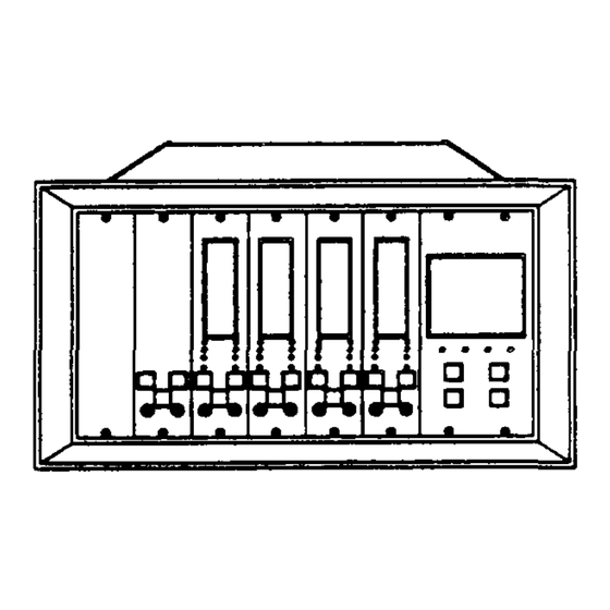
• Case Expansion Monitor Maintenance 84418-01 Case Expansion Monitor System SIGNAL I N P U T R E L AY MODULE LOCATION FOt4111:41 F 4 0 r * 1 4 4 4 1 tg P. . 11 , 4 1 $ 1 . -
Page 33: Front Panel Features
• 84418-01 Case Expansion Monitor Maintenance 1 2 1 F r o n t Panel Features Bergraph - Indicates Case Expansion values 6 S H E • Transducer OK LEDs A - O K Direct Display Indicator Danger LED O N G DI R ECTLJ Q A L R D I FFO Differential D i s p l a y Alert LED... -
Page 34: Monitor Removal
• 84418-01 Case Expansion Monitor Maintenance Monitor Removal CAUTION The machine i s n o t protected when the monitor is removed from the rack. 1. Loosen two screws. 2. Pull monitor from rack. •... -
Page 35: Monitor Disassembly
Case Expansion Monitor Maintenance 84418-01 Monitor Disassembly M A I N C I R C U I T B O A R D STANDOFF ( 4 PLACES) Side Cover Removal Squeeze t h e retaining tips o n each standoff, and remove the side cover from the monitor. - Page 36 • 84418-01 Case Expansion Monitor Maintenance Monitor Disassembly [Cont] Front Panel Removal WASHER RETAINING SPRING SCREW SLIDING STANDOFF V V V M • CONNECTOR V V V V I 0 •...
-
Page 37: S I G N A L Input Relay Module
• 84418-01 Case Expansion Monitor Maintenance Signal Input Relay Module (Dual Relay) WARNING High Voltage present Could cause shock, burns or death. Do Not touch exposed L t 1 1 : 1 wires or terminals. f • E . 4 1 The Signal Input Relay Module is on the back o f t h e r a c k . - Page 38 MONITOR PART NUMBER TRANSDUCER FULL SCALE RANGE I N P U T A L A R M RELAY A P P R O V A L 3300/48 00 = NONE 00 = NOT REQUIRED 01 = 0 - 1.0 inches...
-
Page 39: M O N I T O R Options
• 84418-01 Case Expansion Monitor Maintenance Monitor Options [Cont] The Case Expansion Monitor has several user-programmable options. The options can be changed by removing and installing jumpers on the printed circuit boards. ; - n . . : 1 1 121 1 •alluCaula. - Page 40 • 84418-01 Case Expansion Monitor Maintenance Monitor Options [Cant] Main Board Option Settings An monitor option jumpers for the Case Expansion Monitor are on the Main Board. Table 1 shows these options and their jumper positions. Table 1 Option Settings on Main Board Jumper Option I n s t a l l...
- Page 41 Case Expansion Monitor Maintenance 84418-01 • 6 I Monitor Options [Cont] Table 1 [continued] Jumper Option Setting Install R e m o v e Upscale Channel A T o w a r d Transducer *W12C Away from Transducer Upscale Channel B Toward Probe * W 1 2 B Away from Probe Note : Both channels must be configured in the same direction.
- Page 42 • Case Expansion Monitor Maintenance 84418-01 Monitor Options [Cont] Transducer Type Options To set the monitor up for the correct transducer type, remove all jumpers from headers W22A-D, W21C and D, W4A-F, W16 and W17. Install jumpers specified in Table 3. Table 3.
- Page 43 • 84418-01 Case Expansion Monitor Maintenance 1 7 I Meter Scale Replacement The Monitor meter scales can b e replaced for operation with different full scale ranges. The replacement meter scales are located in the back of this manual. To replace a meter scale : 1.
- Page 44 • Case Expansion Monitor Maintenance 84418-01 1 8 1 Alarm Setpoint Adjust The 3300 Case Expansion Monitor has alarm setpoints for the differential values only. The alarm setpoints are adjusted on the left side of the display. To adjust the differential alarm setpoints, use the following procedure.
-
Page 45: Bypass Monitor Channel
• 84418-01 Case Expansion Monitor Maintenance Bypass Monitor Channel Set B A (Bypass Channel A ) o r B B (Bypass channel B) switch t o the left (ON). The corresponding Bypass LED goes on, the OK LED goes off, and the Case Expansion reading is clamped to Zero. -
Page 46: Danger Bypass
• 84418-01 Case Expansion Monitor Maintenance 1 10 I Danger Bypass Set DB (Danger Bypass) switch to the left (ON). Both channel Bypass LEDs go on. The Danger alarm LEDs on the front panel can go on but the danger relay drive will not be activated if a Danger Setpoint is exceeded. - Page 47 • 84418-01 Case Expansion Monitor Maintenance 111 I Test Channel Alarms 7 7 1 CAUTION SHAFT C E N T E R L I N E LVDT Tests will exceed alarm setpoint levels causing alarms to activate. 4 1 ) 0 0 0 This could result in relay contact to change state.
-
Page 48: Test Channel Alarms
• 84418-01 Case Expansion Monitor Maintenance 11 I Test Channel Alarms 5. Adjust the power supply voltage past the alert setpoint level and verify that the ALERT LED goes on (Flashing if the first out option is selected). It may b e necessary t o switch the polarity a t the power supply to exceed the setpoint. - Page 49 84418-01 Case Expansion Monitor Maintenance 10. Press RESET switch on system monitor. Verify that ALERT and DANGER LEDs remain on and steady. 11. Reduce the power supply voltage to below the alarm set points and observe that the ALERT and DANGER LEDs go off (if non-latching alarm jumper is installed). Press RESET switch on system monitor to reset latching alarms.
- Page 50 • Case Expansion Monitor Maintenance 84418-01 121 Te s t OK Limits CAUTION 1 0 0 0 SHAFT CENTER L I N E Tests will exceed alarm set point levels causing alarms to activate. 0 0 0 This could result in relay contact to change state.
-
Page 51: Test Ok Limits
• Case Expansion Monitor Maintenance 84418-01 Test OK Limits [Conti 3 3 0 0 1 . . 0 C A S E EXPANSION 7. Adjust the power supply to Zero Vdc. Verify that the MONI T OR OK LED comes back on and the OK relay energizes (if non-latching OK mode is selected). -
Page 52: Calibrate Channels
• Case Expansion Monitor Maintenance 84418-01 13 I Calibrate Channels Figure 1 LVDT CAUTION Both channels will b e bypassed automatically during calibration. Machine Protection will b e lost during calibration. S e e Danger Bypass section 10. SLIDING FOOT FOOT Me lel 1 M N lull... - Page 53 • Case Expansion Monitor Maintenance 84418-01 17171 Calibrate Channels [Cont] 4. Short calibration terminals (CA) using a clip lead (a jumper may be used if the monitor is on an CASE EXPANSION MONITOR extender card). A test pattern will appear on the display when t h e Calibration terminals a r e shorted and no Calibration switches are set.
- Page 54 • Case Expansion Monitor Maintenance 84418-01 Calibrate Channels [Cont] 9. Move the core exactly the total linear distance of the full scale meter range in the upscale direction (opposite of direction of movement in step 6). The transducer output should be within the range indicated if Table 6 on page 24.
- Page 55 • Case Expansion Monitor Maintenance 84418-01 Calibrate Channels [Cont] Table 6 Zero Voltage Full Scale Voltage Toward A w a y from Toward A w a y from Transducer Transducer Transducer Transducer Transducer 1 Inch LVDT -3.6 to -5.4 Vdc +3.6 to +5.4 Vdc +3,6 to +5.4 Vdc -3.6 to -5.4 Vdc...
-
Page 56: Self Test
- performed only when the monitor is turned on cyclic - continuously performed by the monitor user-invoked - performed only when initiated by the user. 3300/48 The monitor on this page is giving a signal that a continuing error has been detected during a CASE EXPANSION self test. - Page 57 Case Expansion Monitor Maintenance 84418-01 Self Test [Cont] Follow these steps to read the error codes that have been stored in the monitor: S3300,4e 3 3 0 0 i 4 1 C A S E EXPANSION C A S E EXP ANSION MONI T OR M O N I T O R A •...
- Page 58 • Case Expansion Monitor Maintenance 84418-01 1 14 I Self Test [Cont] 3300,4s 7700/48 3300,48 CASE EXPANSION CASE EXPANSION CASE EXPANSION M O N I TOP M O N I TOP MONITOR MEMENII=MINV m n i i m m o r 1 - 7 C 5": SS- - T •...
- Page 59 Case E x p a n s i o n M o n i t o r M a i n t e n a n c e 84418-01 • Self Test [Cont] ( E ) 3 3 0 0 , 4 8 S 5 3 0 0 , 4 4 CASE EXPANSION CASE EXPANSION...
- Page 60 • Case Expansion Monitor Maintenance 84418-01 j Self Test [Cont] Error Code Description CHECKSUM has failed. * ( : 5 3 3 0 0 / 4 8 3 E E P R O M failure number 1. ** CASE EXPANSION MONITOR 4 E E P R O M failure number 2 * * * Adjust set points...
-
Page 61: F I E L D Wiring Diagrams
• 84418-01 Case Expansion Monitor Maintenance Field Wiring Diagram 3300/45 FIELD WIRING TRANSDUCER HOUSING ASSEMBLY TRANSDUCER HOUSING ASSEMBLY CHANNEL TERMINAL CHANNEL A TERMINAL BLOCK RECORDER RECORDER BLOCK OUTPUT OUTPUT JUMPER JUMPER DANGER A L E RT RELAY R E L AY CONTACTS CONTACTS •... -
Page 62: Recommended Spare Parts
If the monitor has been modified, specify the modification number on the parts order. User must set programmable options (Reference section 7 of this manual). If in doubt about the part number, call your Bently Nevada Corporation representative before ordering. - Page 63 • 84418-01 rPSE! PTerlrai'71r! MeNnitor M a i r n a r c a Snecifications INPUTS Signal Inputs: Two channels LVDT input, 230K Ohm input impedance. Signal Scale Factors: 9V/inch (0.35V/mm) - 1 Inch LVDT 10V/inch (0.39V/mm) - 2 Inch LVDT 3.5V/inch (0.14V/mm) - 4 Inch LVDT SIGNAL CONDITIONING Monitor Range:...
-
Page 64: S P E C I F I C A T I O N S
• Case Expansion Monitor Maintenance 84418-01 Specifications [Cont] RELAY CONTACT RATINGS Dual Relays: A @ 120 Vac 50/60 Hz. 5 A @ 28 Vdc. ENVIRONMENTAL Temperature: O p e r a t i n g +32°F to +149•F (0°C to +65^C). Storage -40°F to +185°F (-40°C to +85•C). - Page 65 • 84418-01 Case Expansion Monitor Maintenance Adjust Alarm Setpoints Alarm Delay Alert Alert Alarm Alert Mode Alert Relay Alert Setpoints Bar graph Buffered Transducer Output Calibrate Channels Calibration Terminology Channel B Off Channel Bypass Circuit Board Removal Danger Danger Alarm Danger Bypass Danger Mode •...
-
Page 66: Index
• 84418-01 Case Expansion Monitor Maintenance INDEX Spare Parts 32,33 Specifications Test Channel Alarms Test OK Limits Transducer Type Options Upscale Channel A Upscale Channel B User-programmable options Wiring Recommendations • •... -
Page 67: Schematics And Pwa Drawings
Case Expansion Monitor Maintenance APPENDIX • SCHEMATICS AND PWA DRAWINGS • • Appendix... - Page 68 • A / D ' 13 Dizttralitlir Ps/Vs.w 0 !4it!?1 1 7 1 1 1 1 , ! 1 ? 1 ? i l l 1 . • ..• • ..,.., .:9`..,12:-.0:-... se " • • o..•...
- Page 69 2 A 4 M a t A C ; • 4 9 4 4 9 4 n g 4 9 4 4 0 a q q n q 9 9 4 9 9 4 . . 7 9 , 9 A e 11 4 , 1 4 4 . 1 6 1 e 1 v v v v ••••...
- Page 70 • ir:/e gait 2, r :;' I 1 6 4 los% • • • • a t % • B I S • -40444 : I Z Z : s ; ; 4 4 1 . z • • ! W E . e a a S 3 6a &...
- Page 71 171: 57,E -CwQe • Case E x p a n s i o n M o n i t o r S c h e m a t i c S h e e t ( 4 o f 1 1 )
- Page 72 • • Case E x p a n s i o n M o n i t o r S c h e m a t i c S h e e t ( 5 o f 1 1 )
- Page 73 D A T A M A N A G E R I N T E R F A C E • i o _ NgXto a i d V2. X • Case E x p a n s i o n M o n i t o r S c h e m a t i c S h e e t ( 6 o f 1 1 )
- Page 74 mr m T R A N S D U C E R 111,l/1111 C U R R E N T L I M I T D i n C I R C U I T S t-,- 1-6 0 C I A .911111 .
- Page 75 ( F - - 9 - - 3 N= • A l y U : 1 * — C S Case E x p a n s i o n M o n i t o r S c h e m a t i c S h e e t ( 8 o f 1 1 )
- Page 76 • • & I I ) ID U ) ( D m C A S E E X P A N S I O N M O N I T O R 0 0 0 8 / 4 8 I- h V ) TRANDOUCER OPTION N_ANI REL 1-"...
- Page 77 • a - • la a s as 1 1 ! - C a s e E x p a n s i o n M o n i t o r B l o c k D i a g r a m S h e e t ( 1 0 o f 1 1 )
- Page 78 0 0 0 0 0 0 0 0 0 0 0 0 0 0 0 0 0 0 0 0 0 0 0 0 0 0 0 0 0 0 0 0 or t a04----1-0 • 0 0 0 0 0 0 0 0 0 0 0 0 0 0 0 0 0 0 0 0 0 0 0 0 0 0 0 0 0 0 0 0 a l e l o 0 Ho 18 o s i N 000...
- Page 79 Artisan Technology Group is your source for quality new and certified-used/pre-owned equipment SERVICE CENTER REPAIRS WE BUY USED EQUIPMENT • FAST SHIPPING AND DELIVERY Experienced engineers and technicians on staff Sell your excess, underutilized, and idle used equipment at our full-service, in-house repair center We also offer credit for buy-backs and trade-ins •...
Need help?
Do you have a question about the 3300/48 and is the answer not in the manual?
Questions and answers