Table of Contents
Advertisement
Quick Links
Advertisement
Chapters
Table of Contents

Subscribe to Our Youtube Channel
Related Manuals for Bently Nevada 3300/40


Summary of Contents for Bently Nevada 3300/40
- Page 1 Artisan Technology Group is your source for quality new and certified-used/pre-owned equipment SERVICE CENTER REPAIRS WE BUY USED EQUIPMENT • FAST SHIPPING AND DELIVERY Experienced engineers and technicians on staff Sell your excess, underutilized, and idle used equipment at our full-service, in-house repair center We also offer credit for buy-backs and trade-ins •...
- Page 2 • DOCUMENT NO. 82344-01 3300/40 ECCENTRICITY MONITOR OPERATION MANUAL • B E N T L Y r \ N E VA D A • 9 9 B •...
- Page 3 • NOTICE READ THE FOLLOWING BEFORE INSTALLING OR OPERATING EQUIPMENT. Bently Nevado Corporation h a s attempted t o identify areas o f risk created by improper installation a n d / o r operation o f this product. T h e s e areas o f in— formation o r e noted a s WARNING o r CAUTION f o r your protection a n d f o r t h e safe a n d effective operation o f this equipment.
- Page 4 • 3300/40 Eccentricity Monitor Maintenance, 82345-01 • Dynamic Data Manager System, 46390-01 Keyphasorg is a registered trademark of Bently Nevada Corporation Proximitor® is a registered trademark of Bently Nevada Corporation Document No. 82344 • F i r s t Printing: June 1988 • Revision G April 1989 Copyright ©...
- Page 5 Eccentricity Monitor Operator 82344-01 Blank Page...
-
Page 6: Table Of Contents
Eccentricity Monitor Operation CONTENTS TITLE ECCENTRICITY MONITOR SYSTEM MONITOR FUNCTIONS MONITOR OPTIONS PROGRAMMABLE OPTIONS BYPASS A L E RT DANGER MONITOR RANGES • R E A D DIRECT A N D PEAK TO PEAK VALUES READ A L E RT SETPOINT LEVELS READ DANGER SETPOINT LEVELS READ GAP A N D THRESHOLD V O LTA G E LEVELS SELF TEST... - Page 7 Eccentricity Monitor Operation 82344-01 Blank Page...
-
Page 8: Eccentricity Monitor System
Eccentricity Monitor Operation 82344-01 E C C E N T R I C I T Y M O N I T O R S Y S T E M 3300/40 ECCENTRICITY MONITOR • • • 1 • 1 1 1 . -
Page 9: Monitor Functions
82344-01 Eccentricity Monitor Operation 2 MONI T OR F U N C T I O N S S H E E T 1 O F 2 ECCENTRICITY - Eccentricity (ECC) is defined as the variation between the outer diameter of a shaft surface and the true geometric center line of the shaft. - Page 10 82344-01 Eccentricity Monitor Operation • I V E 2 0 2 1 1 1 1 1 1 1 1 i 2 MONITOR F U N C T I O N S S H E E T 2 O F 2 ALARM RELAYS - Monitor alarms can be programmed for both latching and nonlatching mode.
-
Page 11: Monitor Options
82344-01 Eccentricity Monitor Operation M O N I T O R O P T I O N S "PANSDuCE. ,-;P N Ji = ' 2 0 0 , - R A N S C : C E , : C C - ., Mil_ ,c... - Page 12 Eccentricity Monitor Operation TE: THIF OPEPATHr. RANGES FOR THE ECCENTRICITY A N D IKE P H A TRAINDUCERS ,A IRE MONITC1RED. THEREEORE, THE PERFPMANCE O F EITHER TRANSDUCER CAN CAUSE A N O T —OK CONDITION (DEENERGIZED A.NO OK LED T O CO OFE. nix' 1---:--- .
-
Page 13: Bypass
82344-01 Eccentricity Monitor Operation B Y P A S S 5 = - 0 - - 0 0 E C C R E DANGER a K i A L E R T 0 Z B Y P A S S • w . L - . -
Page 14: A L E Rt
Eccentricity Monitor Operation 82344-01 • A L E R T D A N C E R ALERT B Y P A S S • ALERT RELAY DE-. . E L _ _ = _ b) L) ' :-.) r--' L /2\ I COND T ON DIRECT ALARM! DIRECT A , D I R E C T... -
Page 15: Danger
82344-01 Eccentricity Monitor Operation D A N G E R 3— — - o - C D E C C 4 41) DANGER • ALERT T f l BYPASS DANGER RE..-1. _L:I1 71c-F-DLAY C O \ n T I O N DIRECT ALARMI : 7 - - _ - - . -
Page 16: Monitor Ranges
Eccentricity Monitor Operation 82344-01 • M O N I T O R R A N G E S TRANSDUCER 0 p r i o N =AR, NUMBER rULL—SCALE RANGE 3 3 0 0 ' 4 3 TO pcAlc 7200, 5 m m OR 8 m m 01 - 5 - 0 - 5 MILS MILS... -
Page 17: R E A D Direct A N D Peak To Peak Values
82344-01 Eccentricity M o n i t o r Operation • R E A D D I R E C T A N D P E A K T O P E A K V A L U E S D i P F 2,T A N D P E A K T O P E A K V A L E: T PEAK... -
Page 18: Read A L E Rt Setpoint Levels
82344-01 Eccentricity Monitor Operation 1 1 R E A D A L E R T S E T P O I N T L E V E L S A L E R T L . , v.:, : „ L E R Ti R S' N TS (FOR ROTH D I R E C T A PEAK/PEAK... -
Page 19: Read Gap A N D Threshold V O Lta G E Levels
82344-01 Eccentricity Monitor Operation 1 3 READ G A P A N D T H R E S H O L D V O L T A G E L E V E L S RRESS G A P / T H R E S H O L D SWITCH A N D READ VOLTAGE LEVELS (COP AND Kr'rPH,AS,7)P THRESHOLD) USING CENTER SCALE ON METER. - Page 20 Eccentricity Monitor Operation 82344-01 • 1 4 rib., T E S T S H E E T 1 O F 3 H T H R F F LEVELS OF SELF TESTS: k, I o POWER- U P TEST: PERFORMED ONLY WHEN MONITOR I S TURNED ON. •...
- Page 21 Eccentricity Monitor Operation 82344-01 I 14 SELF T E S T S H E E T 2 O F 3 1 1 0 -rST B y MOMENTARILY SHORTING ACROSS TWO SELF T E 1 2 i N S . r° \ MACHINE PROTECTION WILL 5 E DISCONTINUED FOR DURATION O r o AT COMPLETION O F USER-INVOKED TEST, MONITOR WILL RECALL A N Y ST,T-Ri--1-) _ - - .
-
Page 22: Self Test
Eccentricity Monitor Operation 82344-01 S E L F T E S T S H E E T 3 O F 3 1 1 1 1 1•F 11111,7SCR''PTI,:j C >,T= :c: y M i T l P ROM G H F C K j m EE PROM FA I L U R E N O . - Page 23 Eccentricity Monitor Operation INDEX Page Alert Bypass Danger Eccentricity Monitor System Monitor Functions Monitor Options Monitor Ranges Options Programmable Monitor Programmable Options Read Alert Setpoint Levels Read Danger Setpoint Levels Read Direct and Peak to Peak Values Read Gap and Threshold Voltage Levels Self Test Index-1...
- Page 24 DOCUMENT NO. 82345-01 • 3300/40 ECCENTRICITY MONITOR • MAINTENANCE MANUAL • • • • • • E I E N T L Y r \ a*.Ai R .. . c t N E VA D A •...
- Page 25 82345-01 3300/40 Eccentricity Monitor Maintenance NOTICE READ T H E FOLLOWING BEFORE INSTALLING O R 01=-'•PA.7lNG EQUiPMENT. B e n t l y N e v a d o C o r p o r a t i o n h a s a t t e m p t e d t o i d e n t i f y a r e a s o f r i s k c r e a : e d b y i m p r o p e r i n s t a l l a t i o n a n d / o r o p e r a t i o n o f t h i s p r o d u c t .
- Page 26 • 3300/40 Eccentricity Monitor Operation, 82344-01 • Dynamic Data Manager System, 46390-01 Keyphasor® is a registered trademark of Bently Nevada Corporation Proximitor® is a registered trademark of Bently Nevada Corporation Document No. 82345 • F i r s t Printing: October 1988 • Revision F November 1989 Copyright ©...
- Page 27 82345-01 3300/40 Eccentricity Monitor Maintenance Contents Section Page Introduction 1. Monitor Removal 2. Monitor Disassembly Side Cover Removal ....Circuit Board Removal ....
-
Page 28: Monitor Removal
82345-01 3300/40 Eccentricity Monitor Maintenance • 1. Monitor Removal The machine is not protected when the monitor is removed from the rack. 1. Loosen two screws. 2. Pull monitor from rack. • o ' c CI =CI CACI CICI CI '85 CI 8ID85 El &... -
Page 29: Monitor Disassembly
82345-01 3300/40 Eccentricity Monitor Maintenance 2. Monitor Disassembly MAIN CIRCUIT BOARD STANDOFF Side Cover Removal Squeeze the retaining tips on each standoff, and remove the side cover from the monitor. F-:C.ARn Circuit Board Removal Squeeze the retaining tips on each... -
Page 30: Front Panel Removal
3300/40 Eccentricity Monitor Maintenance • F r o n t Panel Removal RETAINING WASHER SLIDING STANDOFF SCREW S P R I N G m o w n RIBBON CABLE •... - Page 31 82345-01 3300/40 Eccentricity Monitor Maintenance 3. Signal Input Relay Modules D u a l Relays A\ WARNING High voltage present could cause shock burns or death a ® 0 I l l Do not touch exposed wires or terminals The Signal Input Relay Module is on fall the back of the rack.
-
Page 32: Signal Input Relay Modules
82345-01 3300/40 Eccentricity Monitor Maintenance 3. Signal Input Relay Modules [Cont.] Q u a d Relays .1 WARNING High voltage present could cause shock burns or death Do not touch exposed wires or terminals 1101 The Signal Input Relay Module is on 1 7 . - Page 33 82345-01 Eccentricity Monitor Maintenance Blank Page...
-
Page 34: Monitor Options
82345-01 3300/40 Eccentricity Monitor Maintenance 4. Monitor Options The Eccentricity Monitor has several user-programmable options. You can change the options by removing and in- stalling jumpers on the printed circuit boards. PWA81786-011 TP1 ■ • • • • • •... -
Page 35: Main Board Option Settings
Direct Alarm Enabled* W13A Disabled Alert Mode Latching* Non-Latching W13D Danger Mode Latching* W13D Non-Latching Danger Bypass Enabled Disabled* W9A, D Alarm Time Delay 0.1 Second 1 Second 3 Second* W9A, D 6 Second II Options shipped from Bently Nevada... -
Page 36: Monitor Full Scale Range Options
W7 C, D C, D A, B * Options shipped from Bently Nevada Monitor Full Scale Range Options For the monitor to work correctly, you need to set jumpers to match the transducer type and range. Remove all jumpers from Main Board terminals W1 A-F, W2 A-F, and W4 A-D. Remove all jumpers from Recorder Board ter- minals W8A-D. -
Page 37: Meter Scale Replacement
82345-01 3300/40 Eccentricity Monitor Maintenance 5. Meter Scale Replacement You can replace the Monitor meter scale to operate with different full scales. The replacement meter scale appears in the back of this manual. 1. Set the monitor full scale range. (See Section 4. Monitor Options.) 2. -
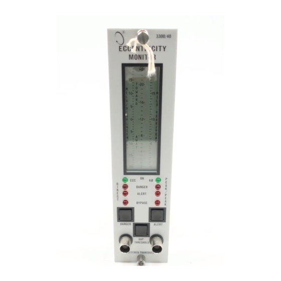
Page 38: Front Panel Features 1
82345-01 3300/40 Eccentricity Monitor Maintenance 6. Front Panel Features 3 3 0 0 / 4 0 ECCENTRICITY MONITOR Bargraph — Indicates instantaneous shaft — 3E position — 2 K Bargraph — Indicates peak to peak eccentricity amplitude when shaft is... -
Page 39: Signal Input Relay Module Features 1
82345-01 3300/40 Eccentricity Monitor Maintenance 7. Signal Input Relay Module Features D C R RECORD T E R M I N A L S E C G P W R I c a C O M Proximity transducer input I - - - - - Proximity transducer input... -
Page 40: 8, Monitor Zero Adjustment
82345-01 3300/40 Eccentricity Monitor Maintenance 8. Monitor Zero Adjustment Use this procedure adjust the Direct scale to zero. NOTE: For greatest accuracy, perform this procedure when the shaft is at rest. If the shaft is rotating faster than 1 /pm, the peak to peak envelope will appear as a bar on the meter. -
Page 41: Keyphasor Threshold Adjustment 1
3300/40 Eccentricity Monitor Maintenance 82345-01 9. Keyphasor Threshold Adjustment Use this procedure to adjust the Keyphasor threshold voltage. NOTE: Before adjusting the Keyphasor threshold, set this option to Manual. (See Section 4. Monitor Options.) The shaft must be rotating. 1. Open the front panel. -
Page 42: Alarm Setpoint Level Adjustment (Peak To Peak) 1
82345-01 3300/40 Eccentricity Monitor Maintenance 10. Alarm Setpoint Level Adjustment (Peak to Peak) Use this procedure to adjust the peak to peak alarm setpoint level. NOTE: The monitor will respond to the previous setpoint level until you perform step 4. -
Page 43: Alarm Setpoint Level Adjustment (Direct)
82345-01 3300/40 Eccentricity Monitor Maintenance 11. Alarm Setpoint Level Adjustment (Direct) Use this procedure to adjust the direct alarm setpoint level. NOTE: DANGER and the ALERT have TOWARD and AWAY setpoint levels. The monitor will respond to the previous setpoint level until you perform step S. -
Page 44: Monitor Bypass
3300/40 Eccentricity Monitor Maintenance 82345-01 • 12. Monitor Bypass Machine protection will be lost while monitor bypass is on. Monitor Bypass puts the monitor out of service. With Monitor Bypass on, the SYSTEM OK relay ignores NOT-OK conditions in the monitor. -
Page 45: Danger Bypass
3300/40 Eccentricity Monitor Maintenance 82345-01 13. Danger Bypass Machine protection will be lost while danger bypass is on. To enable Danger Bypass, install jumper W7 on the Main Board. If you select Danger Bypass, the Danger relay con. tacts will not activate. -
Page 46: Test Direct Alarms 1
82345-01 3300/40 Eccentricity Monitor Maintenance • 14. Test Direct Alarms A\ WARNING High voltage present Steps in this procedure could cause shock will exceed alarm set- burns or death points, activate alarms, Do not touch exposed and activate alarm relay wires or terminals contacts. -
Page 47: Test Peak To Peak Alarms
3300/40 Eccentricity Monitor Maintenance 82345-01 15. Test Peak to Peak Alarms * WARNING Ca:1T High voltage present Steps in this procedure could cause shock will exceed alarm set- burns o r death points, activate alarms, Do not touch exposed and activate alarm relay wires or terminals contacts. -
Page 48: Calibrate Channel
3300/40 Eccentricity Monitor Maintenance 82345-01 • 16. Calibrate Channel WARNING High voltage present Steps in this procedure could cause shock will exceed alarm set- burns or death points, activate alarms, Do not touch exposed and activate alarm relay wires or terminals contacts. -
Page 49: Ok Limits
82345-01 3300/40 Eccentricity Monitor Maintenance 17. O K Limits C O Q A\ WARNING High voltage present Steps in this procedure could cause shock will exceed alarm set- burns or death points, activate alarms, Do not touch exposed and activate alarm relay wires or terminals contacts. -
Page 50: Field Wiring Diagrams
3300/40 Eccentricity Monitor Maintenance 82345-01 • 18. Field Wiring Diagrams 1. Wiring Recommendations Signal module to Proximitor modules: 18-AWG to 22-AWG solid or stranded 3-wire shielded with insulating sheath. Signal module to Recorder/Readout: 18-AWG to 22-AWG solid or stranded 2-wire shielded with insulating sheath. - Page 51 82345-01 3300/40 Eccentricity Monitor Maintenance 1. Wiring Recommendations: Signal Module to Barrier—Barrier to Proximitor transducer: 14-AWG to 18-AWG solid or stranded, 3-wire shielded with insulating sheath. Signal Module to Recorder/Readout: 18-AWG solid or stranded 2-wire shielded with insulating sheath. 2. Shields are joined as shown terminating at Barrier Ground. Shields should be insulated.
-
Page 52: Recommended Spare Parts
3300/40 Eccentricity Monitor Maintenance 82345-01 • 19. Recommended Spare Parts To order replacement parts, specify the complete part number according to this table, as indicated on the identification label. I f the monitor has been modified, specify the modification number on the parts order. T h e customer must set programmable options. -
Page 53: Specifications 2
3300/40 Eccentricity Monitor Maintenance 82345-01 20. Specifications Input Signal Input Two channels with proximity probe signals, one for vibration and one for Keyphasor input Signal Scale Factor 200mV/mil (8 V/mm) or 100 mV/mil (4 V/mm), jumper selectable Signal Conditioning Monitor Range... - Page 54 3300/40 Eccentricity Monitor Maintenance 82345-01 • 20. Specifications [Cont.] Output (Continued) Transducer Power -24 Vdc or -18 Vdc determined by transducer option selected in power supply, short circuit protected Alarms & OK Relay drives for alarms (ALERT and DANGER) and monitor or transducer OK Buffered Output Output terminals on front and rear panels for ECC and Keyphasor transducers.
- Page 55 82345-01 Eccentricity Monitor Maintenance Blank Page...
-
Page 56: Index
82345-01 3300/40 Eccentricity Monitor Maintenance • Index Adjustments Alarm setpoint level (direct) Alarm setpoint level (peak to peak) Keyphasor threshold Monitor zero Alarm setpoint level adjustment direct .... - Page 57 82345-01 3300/40 Eccentricity Monitor Maintenance Schematics and PWA Drawings PWA EIPP MONITOR 1 OF 1 SCHEMATIC DIAGRAM EIPP MONITOR . 81787 9 OF 9 PWA EIPP PIGGYBACK 1 OF 1 SCHEMATIC DIAGRAM EIPP PIGGYBACK 82252 3 OF 3 SCHEMATIC DIAGRAM SIRM .
- Page 58 • OO 0 0 0 0 0 0 0 0 0 0 0 0 0 0 0 o o 0 0 0 0 0 0 0 0 0 0 0 0 M 0 0 0 0 0 0 0 0 0 0 0 0 0 0 0 0 0 0 0 0 0 0 0 0 0 0 0 0 0 0 0 %-CC •...
- Page 59 • 5 , / i'§! ,. . , ; , .., P . , . , • . •m . • 0, • .1 1 • .011 01 • • 4 1 . —i • ao • •...
- Page 60 • • • 1 O I I N O N III II .1 I I I . h 1,1b11. N o C i e • . I ' • L 1 1 ' l o t : BUFFERED k CCI. II I RI CI TN' 1 0 1 0 1140 _ 1 4.42 M t i...
- Page 61 • • • ' I l l ' ( . 1 1 I 1 1 1 It 1 I I I.)1 I !l]UF`_: . r ' H I I l l P I ? u l i L l l t I m l I •...
- Page 62 • • • D I S M I 4 2 H D S 2 1 0 , L I N O W vijc.1-5,-.JiJI-; H I M I t l f C.Rf: f-ICE 11 4.4 0 1 0 0 0 1 1 1 1 0 0 4 0 5 1 2 1 .
- Page 63 • I ! 5641W9Y1bRi • . , - - - • - , 5 1 cr. SCHEMATIC DIAGRAM E I P P MONITOR 8 1 7 8 7 S H 5 O F 9...
- Page 64 • • • H O I I N O N I 1-'1:1.11. I- L Y P H H S O R I H H V 1 S O U R C E S L I E 1;1 I O N U HRA 21 le .
- Page 65 • • • 2 : 1 0 I I N O W ■ J 3 0 t 3 / 411 8 1 1_1( i s I I I 41,1,40r1 1 f 1 " 7 WATERED f f ero RAN KETPetaSIJR ILE motASOR3, "...
- Page 66 • • • ? : 1 0 , L I N O I A I 3:3L:00/4L E CL E N I R IC I TY F L A K T O P E A K P R o u k A r i m i n f I I I LINE J A M 4 0 - - 1 / 1 1 A 1...
- Page 67 • • • : 1 0 , 1 , I N 0 1 4 3 5 0 4 3 / 4 0 S I U N A I N A I I L S A B B R E V I AT I O N S O F T H E S I G N A L S U S E D I N T H E S L H E N A I I L SIGNALS ON P C SCHEMATIC C O M P I E T E SIGNAL NAME SIGNALS O r SGANMATIC C O M P L E T E...
- Page 68 T O - 1 5 2 E 8 b r l d 10m 11213E E . 1 t d l 0 0 0 0 0 0 0 0 0 0 0 0 0 0 0 0 { 1 , 1 _ 1 1 ( - - I - 1 a F971 Y o •...
- Page 69 I C I R C O I C R O - H D J C I R C U I T R Y M.,Idgsg ' F ! _ m _ 1 ol21'i 741' ' 1 7t-1 * * * * ' :1•4 I h v g a i g g a g 3.1.•...
- Page 70 • • • ) I D V H A D D I d R E C O R D E R 1 , 1 0 1 / I 0,4 . 1 1,41 •,14.1 1141E 14IR 11118 1 M , - ) 0 2 6 4 .
- Page 71 • • • ) 1 D V E I X O D I d P R O G R A M ! I A E A F I O N A l l i l k i v I A T I O N S T H E S I G N A L U S L...
- Page 72 • PA L LKS135 -2 . 5 . 2 0 • 3 0 0 0 2 . 0 - * ) < = 1 a l . 1 1 1 ' C l a y D R I V E R 2 2 .
- Page 73 • OAMAidiiiiMEMEMTA8tiNA8Si8EAskJilYPJEOAP.!9sm6 fe*SSA'44Widsd9.1 =4.1...=.11v4.17,1=mmmmgc:.:.2==mmmrr.pm.,:vitwmm:m:;..111.r.1.141•IN L T 1 o d t h • • !!aa!! • I A 4 1 IL 4 4 4 M 1 1 111 4 0 0 9 6) 9 ei) 0 0 0 0 0 0 Y g L L g 2 y J N t 1 0 0 0 0 0 0 !
- Page 74 • • SCHEMATIC DIAGRAM Q U A D R E L AY 8 3 7 3 0 S H 1 O F 2...
- Page 75 o r , L L a • . . s I T : N V I P I N — 9 9 6 ) 0 0 0 9 0 0 9 6 0 7,19 6 6 9 9 6 1 tIt - U A L a t I Z O W S �...
- Page 76 • ; i ; ' 5 I§§ 9g,9 4 4 Y q s i ; /1., :17-74 , 7 1 : 1 3 # " l ' I l l ' i 9 9 1 9 r A a T i g l a R I M I A R T. 1 FF1 tt!tL?Ar1,7,18-i "...
- Page 77 Artisan Technology Group is your source for quality new and certified-used/pre-owned equipment SERVICE CENTER REPAIRS WE BUY USED EQUIPMENT • FAST SHIPPING AND DELIVERY Experienced engineers and technicians on staff Sell your excess, underutilized, and idle used equipment at our full-service, in-house repair center We also offer credit for buy-backs and trade-ins •...
Need help?
Do you have a question about the 3300/40 and is the answer not in the manual?
Questions and answers