
Related Manuals for Samlexpower SEC-2430BRM


Summary of Contents for Samlexpower SEC-2430BRM
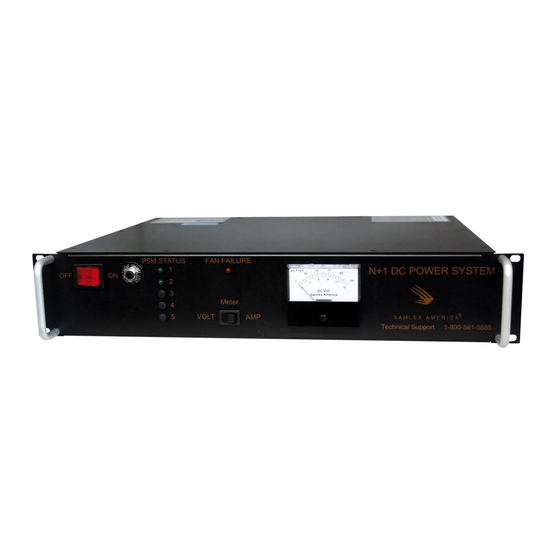
- Page 1 N + 1 DC Power Owner's Please read this manual BEFORE Manual System installing your N + 1 DC Power SEC-2430BRM System SEC-2440BRM SEC-2450BRM...
-
Page 2: Table Of Contents
OWNER'S MANUAL | Index SECTION 1 Important Safety Instructions ..........4 SECTION 2 Description & Application ............ 6 SECTION 3 Design & Principle of Operation ........... 6 SECTION 4 Cooling & Warning for Fan Failure ........7 SECTION 5 Front Panel Controls & Indicators ......... 8 SECTION 6 Rear Panel Controls .............. - Page 3 SECTION 13 Limiting Electromagnetic Interference ........ 18 SECTION 14 Specifications ..............20 SECTION 15 Appendix: Figures 1 to 3 ............ 21 SECTION 16 Warranty ................. 23 SAMLEX AMERICA INC. | 3...
-
Page 4: Important Safety Instructions
20A NEMA 5-20P plug provided with the power cord. SEC- 2430BRM may be powered from a 15A circuit. Although SEC-2430BRM is provided with 20A, NEMA 5-20P plug, this may be powered from a 15A branch circuit if 20A branch circuit is not available. - Page 5 SEC-2450BRM AWG # 4 SEC-2440BRM AWG # 6 SEC-2430BRM AWG # 8 Ensure that the AC power is switched OFF when any device is being connected to the power supply. DO NOT ALLOW the ends of the Positive and Negative wires to touch each other.
-
Page 6: Description & Application
SECTION 2 | Description & Applications Fuse Replacement Ensure properly rated fuse (250V, 4A) is used in each of the modules. Environment DO NOT expose power supply to rain, snow or water spray Dis-assembly And Repair The power supply should be disassembled or repaired by a qualified technician. Incor- rect reassembly or repair may result in a risk of electric shock or fire which may result in personal injury and property damage. -
Page 7: Cooling & Warning For Fan Failure
• SEC-2450BRM has 5 PSMs of 10A each providing a total of 50A • SEC-2440BRM has 4 PSMs of 10A each providing a total of 40A • SEC-2430BRM has 3 PSMs of 10A each providing a total of 30A SECTION 4 | Cooling &... -
Page 8: Front Panel Controls & Indicators
SECTION 5 | Front Panel Controls & Indicators The following controls and indicators are provided on the front panel : 1. A. Power ON/OFF Switch – The rocker switch will illuminate when switched ON. B. Breaker – A 25A circuit breaker provides protection on the input side against overload. 2. - Page 9 SECTION 6 | Rear Panel Connectors Remote Monitoring And Signalling A provision has been made for remote signaling and monitoring of the following operational conditions and parameters: 1. Operational status of the 5 power supply modules (PSM) 2. Failure condition of the cooling fan(s) 3.
-
Page 10: Protections
The “PSM Status” LEDs will, however, remain illuminated, but dimmed. When the overload reaches approximately 70A for SEC-2450BRM or 56A for SEC-2440BRM or 42A for SEC-2430BRM (the output voltage will be approximately 5.4V), the unit will shut down (will enter hiccup mode). -
Page 11: Operation Of Battery Backup
SECTION 8 | Installation & Operation Switch ON the unit by pressing the power ON/OFF switch to ON position. The switch will be illuminated confirming that input power is available. A short beep may be generated by the temperature fault alarm circuit on powering ON the unit . - Page 12 SECTION 9 | Operation of Battery Back-up The voltage at the output terminals load + and load – will be as follows : At no external load approx. 27.8V At 10A load approx. 27.6V At loads > 10A approx. 27.6V minus 5mv per amp above 10A When there is a requirement of un-interrupted D.C.
-
Page 13: Output Voltage Adjustment
SECTION 9 | Operation of Battery Back-up Availability of AC power is signaled for remote monitoring through an opto-coupled signal through the d-sub connector (see page 9 under “Remote Monitoring & SignalI- ing”). This signal may also be used to indicate that the load is being powered by battery (in case external battery is used for battery back-up). - Page 14 SECTION 10 | Output Voltage Adjustment ode D1) is tightly regulated at the preset value of 28V +/-1%, The voltage at the output terminals load + and load - will vary between 27.8V at no load to 27.45V at full load of 50A due to the forward voltage drop of the isolating Schottky Diodes D1 and the drop along the DC bus and wiring.
-
Page 15: Installation & Removal Of Modules
Additional optional module(s) (Model No. SEC-1024MPSB) can be added to upgrade the output current capacity of SEC-2430BRM / SEC-2440BRM by steps of 10A to a maximum of 50A. For example, SEC-2430BRM (30A) can be upgraded to SEC-2440BRM (40A) by adding 1 additional optional 10A module (SEC-1024MPSB) or to SEC-2450BRM (50A) by adding 2 additional optional 10A modules (SEC-1024MPSB). - Page 16 SECTION 11 | Installation & Removal of Modules 5. Terminal marked LED 2 (Fig.1) is used for the front panel LED under “PSM Status (1 to 5)” and terminal marked LED 1 (Fig.1) is used for remote indication through the d-sub con- nector.
-
Page 17: Troubleshooting
SECTION 12 | Troubleshooting POWER ON/OFF SWITCH DOES NOT LIGHT WHEN SWITCHED ON Check that power is available in the AC outlet. - Check that the power cord plug is properly plugged in. BREAKER TRIPS The breaker has tripped due to abnormal condition. Call technical support. “FAN FAILURE”... - Page 18 SECTION 13 | Limiting Electromagnetic Interference (EMI) 1. Switched mode power supplies (SMPS) employ high frequency switching and thus, are a source of radio interference, a recipient of radio interference and a conduit of radio interference (older linear type transformer based power supplies do not employ high frequency switching voltages and will be quieter as compared to switching type of supplies ).
- Page 19 SECTION 13 | Limiting Electromagnetic Interference (EMI) - As explained above, it may trip a GFCI feeding multiple AC outlet circuits / recepta- cles. In such cases, disconnect devices connected to the other AC. - Outlet circuits / receptacles served by this GFCI. 6.
- Page 20 Power Cord Plug 125V, 30A, NEMA L5-30P, Twist Type - SEC-2450BRM Power Cord Plug 125V, 20A, NEMA 5-20P - SEC-2440BRM / SEC-2430BRM Weight, Kg. / Lbs 25 / 55.12 23.5 / 51.7 22 / 48.4 * At Module Output S5, S6 – Fig. 1 Note: Specifications Subject To Change Without Notice 20 | SAMLEX AMERICA INC.
- Page 21 SECTION 15 | Appendix – Figures 1 to 3 LED1 LED2 NOT TO SCALE JUMP1 Figure 1 - Layout of Power Supply Module LEGEND S1 To S4 Holes for 4 Screws to Fasten the Module to the Chassis S5 & S6 Holes for 2 Screw to Connect to the Positive and Negative Output Bus Bars L &...
- Page 22 SECTION 15 | Appendix – Figures 1 to 3 Figure 3. Continuity of "Daisy Chain" Connections Removing any end module (example PSM1/PSM5 in Fig. 2 Above) does not break the daisy chain. However, if any of the sandwiched modules (example PSM 2, 3, 4) is removed, the daisy chain is broken. In this case, the unused female socket for the missing sandwiched module(s) should be shorted by inserting a shorting link to prevent a break in the daisy chain (Fig.3) ...
- Page 23 SECTION 16 | Warranty 2 YEAR LIMITED WARRANTY This product manufactured by Samlex America, Inc. (the “Warrantor“) is warranted to be free from defects in workmanship and materials under normal use and service. The warranty period is 2 years for the United States and Canada, and is in effect from the date of purchase by the user (the “Purchaser“).
- Page 24 Contact Information Toll Free Numbers Ph: 800 561 5885 Fax: 888 814 5210 Local Numbers Ph: 604 525 3836 Fax: 604 525 5221 Website www.samlexamerica.com USA Shipping Warehouse Kent WA Canadian Shipping Warehouse Delta BC Email purchase orders to orders@samlexamerica.com 11001-SEC-2430-2440-2450BRM-1219...
Need help?
Do you have a question about the SEC-2430BRM and is the answer not in the manual?
Questions and answers