Epson EB-1480Fi Installation Manual
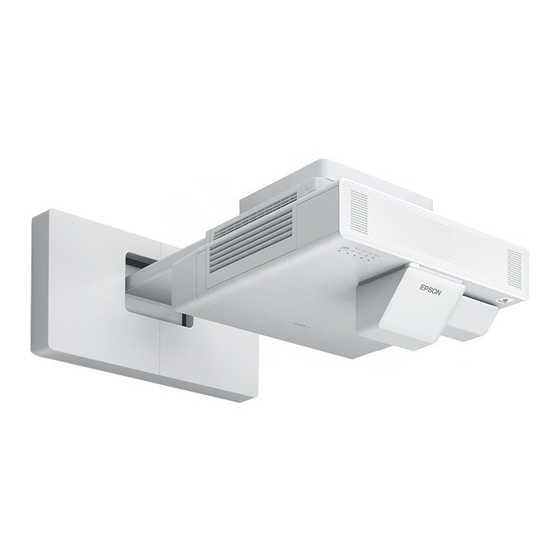
Ultra-short throw projector with touch unit and touch unit bracket
Hide thumbs
Also See for EB-1480Fi:
- Installation manual (142 pages) ,
- User manual (296 pages) ,
- User manual supplement (48 pages)
Table of Contents
Advertisement
Advertisement
Table of Contents

Related Manuals for Epson EB-1480Fi


Summary of Contents for Epson EB-1480Fi
- Page 1 Installation Guide...
-
Page 2: About This Installation Guide
About This Installation Guide Contents of this Guide This guide contains the following information. Installing an ultra-short throw projector (EB-1480Fi) using the wall mount supplied Installing the Touch Unit (ELPFT01) Installing the Touch Unit using the touch unit bracket (ELPMB63) ... -
Page 3: Table Of Contents
Contents Attaching the adjustment unit to the About This Installation Guide projector ......34 Contents of this Guide . - Page 4 Contents Adjustment range ..... . 77 When using an older model of Touch Unit ....... . 78 Installing the Touch Unit .
-
Page 5: Introduction
Introduction Using the Product Safely For your safety, read all the instructions in this guide before using this product. Incorrect handling that ignores instructions in this guide could damage this product or could result in personal injury or property damage. Keep this installation guide at hand for future reference. -
Page 6: Package Contents
If a wall mount has not been supplied with the projector, purchase the optional mount (ELPMB62). To install the projector using the ELPMB62, see the Installation Guide for the EB-1485Fi on the following website. http://epson.sn/ The pen stand may not be included depending on the area of purchase. -
Page 7: Accessories
Introduction Accessories Part Name Application Cable binding belt Secure excess cables after performing wiring. Safety wire set Connect to the wall mount and the projector to prevent the projector from falling. See the user's guide supplied with the safety wire set for more details. Hexagon wrench (for M4) Spanner (No. -
Page 8: Touch Unit Bracket (Optional)
Introduction Part Name Application Markers x2 Attach to the screen to adjust the angle of the laser emitted by the Touch Unit. When the finger touch op‐ erations do not work cor‐ rectly, you need to use the markers again to re-cali‐ brate the angle of the laser. -
Page 9: Pen Stand
Introduction Pen stand Part Name Application Main unit Cover Attach to the front of the pen stand. Spacers for screw holes x3 Attach them to the screw hole when securing the pen stand with screws. Necessary Items As well as the items supplied, you also need to prepare the following screws and tools. Applicable parts Necessary items For the Touch Unit... -
Page 10: Installation Work Flow
Introduction Installation Work Flow We recommend installing the projector and peripheral devices in the following order. Mount projector on wall and adjust the projected image ( p.12) Install the pen stand ( p.60) Perform pen calibration ( p.65) Install and adjust touch unit and perform finger touch calibration ( p.69) When you want to use the installed Touch Unit (see the following image) as it is, adjust the laser angle ( p.90). -
Page 11: Figures Of Installation Dimensions
Introduction Figures of Installation Dimensions When using the Touch Unit, install the projector so that there is a gap between the projected image and the edges of the screen as shown in the following image. 5.7 - 50mm (20 - 50mm (21:9)) 100mm 100mm 20mm... -
Page 12: Connection Figure
Introduction Connection Figure Connecting Multiple Projectors If interactive pen operations interfere with projectors that have been installed nearby, connect the projectors by using the optional remote control cable set (ELPKC28). You can reduce the interference caused by the interactive pen by setting Installation of Projectors > Sync of Projectors to Wired from the Pen/Touch menu after connecting. -
Page 13: Cautions On Installing The Wall Mount
Wall mount and resist any horizontal vibration. Use M10 or 3/8 inch x 60 mm nuts and bolts. Nuts and bolts smaller than M10 or 3/8 inch x 60 mm could cause the setting plate to fall. Epson accepts no responsibility for any damage or injury caused by lack of wall strength or inadequate installation. - Page 14 If any abnormalities occur with this product, immediately disconnect the cables from the product, and then contact your local dealer or the nearest Epson service call center. Continuing to use the product in an abnormal condition could cause a fire, electric shock, or visual...
- Page 15 Installing the Wall mount Warning Laser warning labels have been attached to the inside and outside of the projector. Internal External Do not look into the laser beam emitted from the projection lens while projecting. (Based on IEC/ EN60825-1:2014) For North/South America This projector is a Class 2 laser product that complies with the IEC/EN60825-1:2007 international standard for lasers.
- Page 16 Installing the Wall mount Warning Never open any cases on the projector. Electrical voltages inside the projector can cause severe injury. Do not look directly into the projector’s light source. Possibly hazardous optical radiation emitted from this product. Eye injury may result. Caution Do not install this product in a location where the operating temperature for your projector model may be exceeded.
-
Page 17: The Wall Mount
Installing the Wall mount Cautions on the Installation Location of the Wall Mount Warning Do not install in a location subject to oily smoke or smoke for events. If oils and so on stick to the slide plate fixing part of the projector, the case may crack and cause the projector to fall, resulting in personal injury or property damage. - Page 18 Installing the Wall mount Caution When installing two or more projectors in parallel, leave a gap of at least 1,200 mm between the projectors. 1200mm If you cannot secure a gap of approx. 1,200 mm, install a partition to block the heat vented from the projector's air exhaust vent.
-
Page 19: Wall Mount Specifications
Maximum load capacity Approx. 15.0 kg About replacement installations When replacing an installed projector with EB-1480Fi and you want to project images in the same position, check if the following conditions are met. The installed projector is one of the following: ... -
Page 20: External Dimensions
Installing the Wall mount External dimensions 2 x M4 547.6 LENS CENTER 70.6 472.8 - 174.8 208.5 4 x M4... -
Page 21: Adjustment Range
Installing the Wall mount Adjustment range Vertical slide Horizontal slide Forward/backward slide 0 - 297.9... -
Page 22: Installing Accessories
Installing the Wall mount Installing Accessories When installing a switcher or a tuner, use the screw holes shown in the figure below to secure them. 2 x M4 Before installing, check that the total weight, including the projector and connection cables, is below the maximum load capacity for the Wall Mount. -
Page 23: Mount
Route the cables before installing the wall mount according to your installation environment. This manual describes the installation procedure when using the wall mount supplied with the EB-1480Fi. To install the projector using the ELPMB62, see the Installation Guide for the EB-1485Fi on the following website. -
Page 24: Installing The Bracket
Installing the Wall mount Installing the Bracket Determining the installation position (projection distance tables) Determine the installation position of the wall plate according to the size of the screen (S) you want to project on to. See the following figure to check the values from a to d. This is the value when the setting plate is in the middle of the wall plate (See in the following illustration). - Page 25 Installing the Wall mount See the following for the value of c when projecting at an aspect ratio of 21:9. When using the interactive features with an aspect ratio of 21:9, set the Screen Position to a vertically central or higher position. ...
- Page 26 Installing the Wall mount 16:9 projected image [Unit: mm] 65" 1439 × 809 66" 1461 × 822 67" 1483 × 834 68" 1505 × 847 69" 1528 × 859 70" 1550 × 872 71" 1572 × 884 72" 1594 × 897 73"...
- Page 27 Installing the Wall mount 90" 1992 × 1121 91" 2015 × 1133 92" 2037 × 1146 93" 2059 × 1158 94" 2081 × 1171 95" 2103 × 1183 96" 2125 × 1195 97" 2147 × 1208 98" 2170 × 1220 99"...
- Page 28 Installing the Wall mount 16:10 projected image [Unit: mm] 60" 1292 × 808 61" 1314 × 821 62" 1335 × 835 63" 1357 × 848 64" 1379 × 862 65" 1400 × 875 66" 1422 × 888 67" 1443 × 902 68"...
- Page 29 Installing the Wall mount 81" 1745 × 1090 82" 1766 × 1104 83" 1788 × 1117 84" 1809 × 1131 85" 1831 × 1144 86" 1852 × 1158 87" 1874 × 1171 88" 1895 × 1185 89" 1917 × 1198 90"...
- Page 30 Installing the Wall mount 4:3 projected image [Unit: mm] 53" 1077 × 808 54" 1097 × 823 55" 1118 × 838 56" 1138 × 853 57" 1158 × 869 58" 1179 × 884 59" 1199 × 899 60" 1219 × 914 61"...
- Page 31 Installing the Wall mount 81" 1646 × 1234 82" 1666 × 1250 83" 1687 × 1265 84" 1707 × 1280 85" 1727 × 1295 86" 1748 × 1311 87" 1768 × 1326 88" 1788 × 1341 89" 1808 × 1356 90"...
- Page 32 Installing the Wall mount 21:9 projected image [Unit: mm] 62型 1447 × 620 63型 1471 × 630 64型 1494 × 640 65型 1518 × 650 66型 1541 × 660 67型 1564 × 670 68型 1588 × 680 69型 1611 × 690 70型...
-
Page 33: Removing The Currently Installed Projector And Wall Mount
Installing the Wall mount 90" 2101 × 900 91" 2125 × 911 92" 2148 × 921 93" 2171 × 931 94" 2195 × 941 95" 2218 × 951 96" 2241 × 961 97" 2265 × 971 98" 2288 × 981 99"... - Page 34 Installing the Wall mount Remove the cables from the projector Remove the projector from the setting plate Remove the setting plate from the wall plate Remove the hexagonal axis from the setting plate Keep them as you will use these when installing the new mount.
-
Page 35: Attaching The Adjustment Unit To The Projector
Installing the Wall mount Attaching the adjustment unit to the projector Loosen the screws (x2) and remove the cable cover from the projector Loosen the M4 bolt on the adjustment unit, and then align the marks for each part When the position is correct, tighten the M4 bolt. -
Page 36: Attaching The Setting Plate To The Wall Plate
Installing the Wall mount Secure the adjustment unit to the base of the projector with the M4 x 12 mm bolts (x4) supplied Attaching the setting plate to the wall plate Loosen the M4 x 12 mm bolts (x2) and extend the arm slide on the setting plate Adjust the scale on the slider to the combined distance of the value for (b) confirmed in the projection distance table ( p.23) and the thickness of the projection surface (x). - Page 37 Installing the Wall mount Insert the hexagonal axis into the setting plate Prepare the hexagonal axis that you removed.
- Page 38 Installing the Wall mount Route the necessary cables through the setting plate Warning Do not hang the rest of the cable over the setting plate. They could fall and cause an accident. The following connection ports should be routed so that they come out of the lower part of the setting plate and not through walls.
- Page 39 Installing the Wall mount Attach the setting plate to the wall plate Insert the hexagonal axis until the tip extends slightly out of the top of the wall plate and the other end connects to the bottom of the wall plate. Caution Take care not to trap the cables between the setting plate and wall plate.
- Page 40 Installing the Wall mount Temporarily secure the setting plate Secure three points with the M6 screws supplied (x3). Adjust the vertical slide with the open-ended spanner to align the marks on the wall plate and the setting plate.
-
Page 41: Attaching The Adjustment Unit To The Setting Plate
Installing the Wall mount Tighten the M6 bolt (x1) to secure the setting plate in position Attaching the adjustment unit to the setting plate Attach the adjustment unit to the setting plate with the M4 x 12 mm bolts (x4) supplied Connect the cables to the projector Connect the power cord last. -
Page 42: Attaching Peripheral Devices
Installing the Wall mount Attaching peripheral devices Attaching external tuners and accessories Use commercially available M4 screws to secure external tuners and accessories to the screw holes as shown in the following figure. Adjusting the position of the projected image You can use any of the following methods to adjust the position of the projected image. -
Page 43: Preparations Before Adjusting
Installing the Wall mount Adjusting using the projector menus ( p.51) Select the area you want to adjust and manually correct the image. This is useful when you want to make fine adjustments to the projection position after making mechanical adjustments using the guide screen. Quick Corner Arc Correction Point Correction... - Page 44 Installing the Wall mount Open the projector’s front cover, and then perform approximate focus adjustment using the focus lever Press the [Menu] button Using the Remote Control Using the Control Panel Select Screen Type from the Installation menu to set the aspect ratio of the projected image If necessary, set the projection position by using Screen Position from the Installation menu.
-
Page 45: Auto Screen Adjustment
Installing the Wall mount Change the aspect ratio if necessary Project images from a connected device, and then press the [Aspect] button on the remote control. Each time you press the button, you see the aspect name on the screen and the aspect ratio changes. The aspect ratio does not change when no images are being projected from the connected device. - Page 46 Installing the Wall mount Place the corner markers at the four corners of the position you want to project to Corner markers cannot be placed again. We recommend marking the position where you want to place the markers in advance. ...
- Page 47 Installing the Wall mount Select Auto Screen Adjustment from the Installation menu You see the guidance screen for Auto Screen Adjustment. Loosen all of the adjustment dials and adjustment screws Move the projector to adjust the position of the image so that the yellow areas at the four corners of the guidance screen overlap with the corner markers Make sure that all of the corner markers are within the yellow areas.
-
Page 48: Performing Mechanical Adjustment Using The Setting Plate Installation Guide
Installing the Wall mount When you determine the position, tighten all of the adjustment dials and adjustment screws that you loosened in step 4 Warning Tighten all bolts and screws firmly. Otherwise, the product may fall and cause personal injury or property damage. - Page 49 Installing the Wall mount Press the [Menu] button Using the Remote Control Using the Control Panel Select Setting Plate Installation Guide from the Installation menu You see the guidance screen. Turn the adjustment dial in the installation guide to adjust the horizontal roll...
- Page 50 Installing the Wall mount Loosen the M4 screw, and then turn the adjustment dial in the installation guide to adjust the horizontal rotation Turn the adjustment dial in the installation guide to adjust the vertical tilt Loosen the M4 bolt, and then adjust the horizontal slide...
- Page 51 Installing the Wall mount Loosen the M4 bolts (x2), and then adjust the forward/backward slide Loosen the M6 bolt, and then adjust the vertical slide Re-tighten the screws and bolts that you loosened in steps 3 to 8 Warning Tighten all bolts and screws firmly. Otherwise, the product may fall and cause personal injury or property damage.
-
Page 52: Adjusting Using The Projector Menus
Installing the Wall mount Adjust the focus of position A in the following figure When you have finished making adjustments, press the [Esc] button on the remote control or the control panel to exit the guidance screen Adjusting using the projector menus ... - Page 53 Installing the Wall mount Select Geometry Correction from the Installation menu Select Arc Correction...
- Page 54 Installing the Wall mount Select the side you want to correct and make adjustment When you reach a range that cannot be adjusted, you see the message Cannot adjust any further. displayed. When you have finished making adjustments, press the [Esc] button on the remote control or the control panel to finish adjustment Quick Corner Press the [Menu] button...
- Page 55 Installing the Wall mount Select Geometry Correction from the Installation menu Select Quick Corner...
- Page 56 Installing the Wall mount Select the side you want to correct and make adjustment When you reach a range that cannot be adjusted, you see the message Cannot adjust any further. displayed. While adjusting the sides, press buttons [1], [3], [7], and [9] on the remote control to select the side you want to adjust.
- Page 57 Installing the Wall mount Select Geometry Correction from the Installation menu Select Point Correction Select Point Correction and then select the number of grid...
-
Page 58: Attaching The Covers
Installing the Wall mount Select the points you want to correct and make adjustment If it is hard to see the grid, use Pattern Color to change the color of the grid. When you have finished making adjustments, press the [Esc] button on the remote control or the control panel to finish adjustment Attaching the covers Prepare the wall plate covers and end cap you removed. - Page 59 Installing the Wall mount Attach the right wall plate cover Fit the end cap to the setting plate If you are concerned about the groove in the arm, stick the supplied masking sticker.
-
Page 60: Attaching A Security Cable
Installing the Wall mount Attach the cable cover to the projector, and then secure it with the screws (x2) Attaching a Security Cable Perform one of the following security measures if necessary. Install a commercially available theft-prevention wire lock Pass the wire lock through the security cable installation points on the projector and the setting plate. -
Page 61: Installing The Pen Stand
Installing the pen stand Notes on the Pen Stand Warning Do not go near the pen stand if you are using medical equipment such as a pace maker. Furthermore, when using the pen stand, make sure there is no one using medical equip‐ ment such as a pace maker, in the surrounding area. -
Page 62: Pen Stand Specifications
Installing the pen stand Pen Stand Specifications Item Specification Pen stand mass Approx. 93 g External dimensions [Unit: mm] 36.7 101.9 28.8 44.4 28.8 10.2 2 x M4... -
Page 63: Installing The Pen Stand
Installing the pen stand Installing the Pen Stand Secure the pen stand with magnets or commercially available M4 screws. When securing with magnets Check the installation position and secure with magnets Caution Powerful magnets are used which can cause injury if you trap your fingers. Be careful not to trap your fingers or any other part of your body between the magnets and the installation surface. -
Page 64: When Securing With Screws
Installing the pen stand Store the interactive pens When securing with screws Check the installation position and secure with commercially available M4 screws (20 mm Warning When screwing, make sure they are not tilted at an angle to the installation surface. ... - Page 65 Installing the pen stand Attach the cover Store the interactive pens...
-
Page 66: Adjusting The Interactive Pen
Adjusting the Interactive Pen Calibrating the Interactive Pen Adjust the projector’s image before calibrating the pen. There are two methods available for calibrating the pen; Auto Calibration and Manual Calibration. When calibrating the pen for the first time, perform Manual Calibration for optimum calibration. When calibrating the pen for the second time and after, perform Auto Calibration. - Page 67 Adjusting the Interactive Pen Check the screen content, and then select Yes You see a green dot at the top left of the projection screen. Touch the center of the dot with the pen tip of the interactive pen The dot disappears and moves to the next position. Make sure you touch the center of the dot.
-
Page 68: Auto Calibration
Adjusting the Interactive Pen Repeat step 4 until all of the dots disappear The dot appears at the top left first and then moves towards the bottom right. When all of the dots disappear, Manual Calibration is complete. Check that there are no obstacles between the interactive pen and the Interactive pen receiver (shown below). - Page 69 Adjusting the Interactive Pen Select Auto Calibration from the Pen/Touch menu Check that the pattern image fits into the projected image, and then select Yes Pen calibration starts automatically. If Auto Calibration fails, follow the on-screen instructions to check your surroundings. Or, perform Manual Calibration.
-
Page 70: Installing The Touch Unit
The Touch Unit contains a high power laser product that could cause a fire, electric shock, or an accident. Only connect the Touch Unit to the EB-1480Fi or . Do not connect it to any other projectors or devices. The device could malfunction, or laser light that is higher than normal intensity could be emitted. -
Page 71: For Canadian Users
Installing the Touch Unit Supplier's DECLARATION of CONFORMITY According to 47CFR, Part 2 and 15 Other Class B digital devices & peripherals Epson America, Inc. Located at: 3840 Kilroy Airport Way Long Beach, CA 90806 Tel: 562-981-3840 Declare under sole responsibility that the product identified herein, complies with 47CFR Part 2 and 15 of the FCC rules as a Class B digital device. -
Page 72: Touch Unit Installation Location
Installing the Touch Unit Touch Unit installation location The procedure differs depending on where the Touch Unit is installed. When installed on the projection surface: Secure When installed on a different surface: Secure with the with magnets or screws Touch Unit Bracket Caution When using the Touch Unit, images should be projected onto the front of the screen. -
Page 73: Notes On The Touch Unit Bracket
Installing the Touch Unit Notes on the Touch Unit Bracket Caution If there is a frame around the screen, make sure that the thickness of the top of the frame is less than 3 mm. If the thickness of the top of the screen exceeds 3 mm, the Touch Unit will not operate correctly. 0 - 3mm Make sure that the distance from the wall to the surface of the screen is less than 50 mm. -
Page 74: Notes On The Laser
Installing the Touch Unit Notes on the Laser Attached labels The Touch Unit is a Class 1 laser product that conforms to the IEC/EN60825-1:2014 standard. The Touch Unit is a Class 1 laser product that conforms to the IEC/EN60825-1:2007 standard. (For North/South America.) There are warning labels affixed to the Touch Unit to indicate that it is a Class 1 laser product. - Page 75 Installing the Touch Unit Wavelength: 932 to 952 nm...
-
Page 76: Touch Unit Specifications
Installing the Touch Unit Touch Unit Specifications Item Specification Touch unit mass Approx. 0.6 kg Operating temperature 0 to 40°C Power (supplied from the projector) 5 VDC 0.65 A External dimensions 38.2 2 x M4... -
Page 77: Touch Unit Bracket Specifications
Installing the Touch Unit Touch Unit Bracket Specifications Item Specification Touch unit bracket mass Approx. 1.8 kg Maximum load capacity Approx. 8.8 kg External dimensions 11.5... -
Page 78: Adjustment Range
Installing the Touch Unit Adjustment range 79.5 - 140.5 15 - 76... -
Page 79: When Using An Older Model Of Touch
Installing the Touch Unit When using an older model of Touch Unit Touch Units that have been used with previous projector models can be connected to the EB-1480Fi and used again. After connecting, follow the steps below to setup the Touch Unit. -
Page 80: Installing The Touch Unit
Installing the Touch Unit Installing the Touch Unit Installing the infrared deflectors Stick the infrared deflectors to any obstacles, such as a frame or tray, at the bottom of the projection surface. If there are any obstacles, the laser is reflected as shown below, and the location of your finger will not be detected correctly. -
Page 81: Installing The Touch Unit
Installing the Touch Unit Installing the Touch Unit When installing on the projection surface without using the Touch Unit Bracket Turn on the projector, and then press the [Menu] button Using the Remote Control Using the Control Panel Select Touch Unit from the Installation menu... - Page 82 Installing the Touch Unit Select Installation Pattern You see the installation pattern on the projected image. When installing on a magnetic surface, check the installation position and attach the touch unit with magnets When installing on a non-magnetic surface, go to the next step. Caution Powerful magnets are used which can cause injury if you trap your fingers.
- Page 83 Installing the Touch Unit When installing on a non-magnetic surface, attach the template sheet to the Touch Unit installation position As shown below, attach the bottom of the template sheet onto the installation pattern. Drill holes in the installation surface, and then remove the template sheet Attach the spacers supplied (x2) to the screw holes on the back of the Touch Unit Remove the rubber caps (x2) from the front of the Touch Unit...
-
Page 84: When Using The Touch Unit Bracket To Install Outside Of The Projection Surface
Installing the Touch Unit Secure the Touch Unit with commercially available M4 screws (x2) The following shows the depth of the screw holes in the Touch Unit. 20.4mm Attach the rubber caps that you removed in step 8 to the screw holes on the front of the Touch Unit When using the Touch Unit Bracket to install outside of the projection surface Turn on the projector, and then press the [Menu] button... - Page 85 Installing the Touch Unit Select Touch Unit from the Installation menu Select Installation Pattern You see the installation pattern on the projected image.
- Page 86 Installing the Touch Unit Attach the template sheet for the Touch Unit Bracket Align the top edge of the projection surface with the bottom edge of the template sheet. If there is a gap between the installation surface for the bracket and the projection surface, we recommend drawing marks in advance at the attachment position.
- Page 87 Installing the Touch Unit Loosen the screws (x2) at the top of the Touch Unit Bracket Slide the parts at the front of the bracket forward until they are fully extended To prevent the sliding section from slipping during installation, lightly tighten the top screws (x2) that you loosened in step 6.
- Page 88 Installing the Touch Unit Slide the bracket so that it fits with the projection screen Slide it in until the lower edge of the bracket touches the projection screen. Remove the rubber caps (x2) from the front of the Touch Unit...
-
Page 89: Attaching A Security Cable
Installing the Touch Unit Secure the Touch Unit to the bracket with the M4 x 25 mm bolts (x2) supplied Caution There is a powerful magnet on the rear of the Touch Unit. Do not trap your hand between the Touch Unit and the Touch Unit Bracket. -
Page 90: Turning On The Touch Unit
Installing the Touch Unit Turning on the Touch Unit Connect the Touch Unit connection cable that is connected to the projector to the TCH port on the Touch Unit Select Touch Unit from the Installation menu Set Power to On The Touch Unit turns on and the indicator is lit blue. -
Page 91: Adjusting The Angle Of The Laser (Touch Unit Auto Setup)
Installing the Touch Unit Adjusting the Angle of the Laser (Touch Unit Auto Setup) An infrared laser in the shape of a curtain is emitted from the Touch Unit. The infrared laser reflects off your finger when touched to the projection surface thereby detecting the finger position allowing the projector's infrared camera to recognize the position being reflected. - Page 92 Installing the Touch Unit When the laser is not parallel to the screen The position of your finger may not be detected The position of your finger detected by the pro‐ even if you touch the projected image. jector and your actual finger position may not ...
- Page 93 Installing the Touch Unit Select whether or not the Touch Unit Bracket is being used The following steps differ if you are using an older model of Touch Unit. Follow the on-screen instructions. For details on performing operations, see the Installation Guide supplied with the old projector.
- Page 94 Installing the Touch Unit Place the two markers supplied on the marker positions on the projection screen and secure them Magnetic screens: Place the base of the markers onto the screen. Non-magnetic screens: Use the supplied tape to secure the markers as shown below. Do not place anything other than the markers near the projected image during angle adjustment.
- Page 95 Installing the Touch Unit Touch ( ) displayed on the screen with your finger and check if ( ) is displayed in the same position Touch all four ( ) to confirm. Screen Status Adjustment has been performed correctly if the lo‐ cation you touch with your finger is the same place as where ( ) is displayed.
-
Page 96: When Auto Adjustment Fails
Installing the Touch Unit When auto adjustment fails Check that the Touch Unit installation position is correct Make sure that the Touch Unit and the projected image are parallel. If you are using a Touch Unit Bracket, make sure that the bottom edge of the bracket is flush with the edge of the projection surface without any gaps. - Page 97 Installing the Touch Unit Check the message displayed and take the necessary action Screen Solution Follow the on-screen instructions to adjust the angle of the laser, and then perform auto adjust‐ ment again. For details, see "Adjusting the angle of the laser" p.96. Check the following after removing the markers from the projection surface.
- Page 98 Installing the Touch Unit Press the Enter button You see the following adjustment screen. Turn the adjustment screw clockwise to cover the left and right pointers Press the [Enter] button to start Touch Unit auto adjustment...
-
Page 99: Calibrating The Touch Operation Position
Installing the Touch Unit When adjustment is complete and you see the following screen, remove the markers from the projection surface If you see a message notifying you that auto adjustment has failed, check "When auto adjustment fails" p.95. Calibrating the touch operation position Perform touch calibration so that the projector can recognize touch operations precisely. - Page 100 Installing the Touch Unit Select Touch Calibration Select Yes You see a dot at the top left of the projection screen. Touch the center of the dot with your finger When the dot disappears and moves to the next position, remove your finger. ...
- Page 101 Installing the Touch Unit Repeat step 5 until all of the dots disappear When all of the dots disappear, touch calibration is complete. If you touch the wrong position, press the [Esc] button on the remote control or control panel. This returns you to the previous dot.
-
Page 102: Setting The Projector
Setup by connecting the computer and projector with a USB cable. Make settings using Epson Projector Management. This guide explains the USB flash drive and the USB cable methods. For details on making settings using Epson Projector Management, see the Epson Projector Management Operation Guide. ... -
Page 103: Copying Saved Settings To Other Projectors
Setting the Projector Connect the USB flash drive to the projector's USB-A port Connect the USB flash drive directly to the projector. If the USB flash drive is connected to the projector through a USB hub, the settings may not be saved correctly. ... -
Page 104: Setup By Connecting The Computer And Projector With A Usb Cable
Setting the Projector Connect the USB flash drive containing the saved batch setup file to the projector's USB-A port Do not store any data except for the batch setup file on the USB flash drive. If the USB flash drive contains data other than the batch setup file, the settings may not be copied correctly. While holding down the [Menu] button on the remote control or the control panel, connect the power cord to the projector The Power indicator and the Status indicator turn blue, and the Laser indicator and the Temp indicator... -
Page 105: Copying Saved Settings To Other Projectors
Setting the Projector Connect the computer's USB port to the projector's USB-B port with a USB cable While holding down the [Esc] button on the remote control or the control panel, connect the power cord to the projector The Power indicator and the Status indicator turn blue, and the Laser indicator and the Temp indicator turn orange. - Page 106 Setting the Projector While holding down the [Menu] button on the remote control or the control panel, connect the power cord to the projector The Power indicator and the Status indicator turn blue, and the Laser indicator and the Temp indicator turn orange.
-
Page 107: When Setup Fails
Writing the settings may have failed and an error may have occurred blue, and the Laser and the Temp indica‐ in the projector's firmware. Stop using the projector, remove the tors flashing orange quickly? power plug from the electrical outlet, and contact Epson for help. -
Page 108: Appendix
Appendix List of Safety Symbols The following table lists the meaning of the safety symbols labeled on the equipment. Symbol mark Approved stand‐ Meaning ards IEC60417 "ON" (power) No.5007 To indicate connection to the mains. IEC60417 "OFF" (power) No.5008 To indicate disconnection from the mains. IEC60417 Standby No.5009... - Page 109 Appendix Symbol mark Approved stand‐ Meaning ards IEC60417 Alternating current No.5032 To indicate on the rating plate that the equipment is suitable for alternating current only; to identify relevant terminals. IEC60417 Direct current No.5031 To indicate on the rating plate that the equipment is suitable for direct current only;...
- Page 110 Appendix Indication of the manufacturer and the importer in accordance with requirements of directive 2011/65/ EU (RoHS) Manufacturer: SEIKO EPSON CORPORATION Address: 3-5, Owa 3-chome, Suwa-shi, Nagano-ken 392-8502 Japan Telephone: 81-266-52-3131 http://www.epson.com/ Importer: SEIKO EUROPE B.V. Address: Azië building, Atlas ArenA, Hoogoorddreef 5, 1101 BA Amster‐...
-
Page 111: General Notice
Appendix General Notice Mac and OS X are trademarks of Apple Inc.. Microsoft and Windows are trademarks or registered trademarks of Microsoft Corporation in the United States and/or other countries. © 2020 Seiko Epson Corporation 2020.07 413912200ENPDF...
Need help?
Do you have a question about the EB-1480Fi and is the answer not in the manual?
Questions and answers