Table of Contents
Advertisement
Quick Links
Advertisement
Table of Contents

Subscribe to Our Youtube Channel
Related Manuals for IFM Electronic ZB0929


Summary of Contents for IFM Electronic ZB0929
- Page 1 Operating instructions Gateway ZB0929...
-
Page 2: Preliminary Note
1 Preliminary note Technical data, approvals, accessories and further information at www.ifm.com. 2 Safety instructions • Read this document before setting up the product and keep it during the entire service life. • The product must be suitable for the corresponding applications and environmental conditions without any restrictions. -
Page 3: Symbols Used
(NB-IoT, 2G or LTE Cat M1) or via a wireless LAN connection. The backend system can be either ifm electronic’s LR Smartobserver (see chapter 8.1) or any other backend system (e.g. a cloud) via MQTT. -
Page 4: Operating And Display Elements
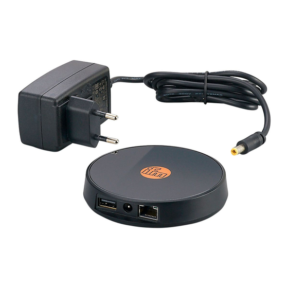
5 Operating and display elements 1: USB connection 2: Mains connection 3: Ethernet connection 4: Micro-SIM card slot 5: Configuration button 6 Electrical connection ► Connect the device with the supplied power supply. 7 Set-up The device switches on automatically when connected to the power supply. -
Page 5: Gateway Configuration
Colour State Meaning green Device is connected to the Internet / network. blue Establish radio connection to the Internet or to the set ping address. flashes The device is in local configuration mode. The device is not connected to the Internet or to the set ping address. - Page 6 The IP address range of device and PC must match the subnet mask. Address Address Address (segment (segment relating relating to to the the network station address) address) Subnet mask 255.255.255.0 255.255.255. Wireless Gateway e.g. 192.168.0.15 192.168.0. e.g. 15 ZB0929 e.g. 192.168.0.10 192.168.0. e.g. 10 ► Configure a DNS server if necessary.
- Page 7 The device can independently send out ping commands, thus allowing for confirmation that a particular host in a network can be reached. In case of a local connection, the host’s IP address, e.g. 192.168.0.10, can be used as the ping address. If an internet connection is required (e.g. when using a cloud), any domain can also be used as a ping address (e.g.
- Page 8 7.2.2 Wireless LAN connection The gateway can be configured as a wireless LAN client. ► Search for and select a wireless LAN network under [Add Wifi network]. 7.2.3 Mobile network connection ► Insert the SIM card before connecting the power supply. ►...
- Page 9 7.2.4 MQTT connection ► Make settings for the MQTT broker. ► Set the broker’s IP address and the port. Usually, ports "1883" and "8883" are reserved for MQTT. If a username and password is available, they can be entered here. TLS encryption can either be activated or deactivated.
-
Page 10: Sensor Setup
7.2.5 Gateway - Change access password ► If necessary, change the factory-set gateway password. The password cannot be reset. 7.3 Sensor setup Recommendation: Due to the mesh topology, arrange the sensors around the gateway. ► Press the button briefly (switch on device). >... -
Page 11: Maintenance, Repair And Disposal
The overview of the approval status of a device is available on our website at www.ifm.com. 10.2 Europe / EU declaration of conformity ifm electronic gmbh hereby declares that the device corresponds to the directive 2014/53/EU. You can find the EU declaration of conformity at the following Internet address: www.ifm.com. - Page 12 This device has been tested and found to comply with the limits for a Class B digital device, pursuant to part 15 of the FCC Rules. These limits are designed to provide reasonable protection against harmful interference in a residential installation.
Need help?
Do you have a question about the ZB0929 and is the answer not in the manual?
Questions and answers