
Subscribe to Our Youtube Channel
Related Manuals for IFM Electronic AS-i DP Series


Summary of Contents for IFM Electronic AS-i DP Series
- Page 1 Device Manual AS-i gateway Profibus DP 1 AS-i master 2 AS-i master AC1335 AC1326 Smart Link DP AS-i DP Gateway AS-i master profile: M3 Firmware: RTS 1.x English...
- Page 2 device manual AS-i DP-Gateway Important note! When this manual was printed, it considered the current state of technology. It is intended for technically trained persons. It was prepared with utmost care. The information, data and notes provided in this manual represent no warranted characteristics.
-
Page 3: Table Of Contents
device manual AS-i DP - Gateway Contents device manual AS-i DP - Gateway: About this manual ................... 1-4 Important safety information!..................1-4 The AS-i DP-Gateway family................2-5 Mounting instructions ..................3-6 Setting up the AS-i System................4-7 AS-i power supply ....................4-7 AS-i diagnosis LEDs ....................4-9 Connecting the slaves ....................4-9 Display menu ......................4-12... -
Page 4: About This Manual
device manual AS-i DP-Gateway 1 About this manual This manual describes the AS-i DP -Gateway family with AS-i version 2.1 master manufactured by ifm electronic gmbh with two AS-i master (Ord.No. AC1326), as well as SmartLink DP with one AS-i master (Ord. -
Page 5: The As-I Dp-Gateway Family
device manual AS-i DP - Gateway 2 The AS-i DP-Gateway family The AS-i DP -Gateway contain 1 (AC1335) or 2 AS-i masters (AC1326) having the AS-i Association’s advanced specification 2.1. This new specification brings the following features to the AS-i DP - Gateway family: ... -
Page 6: Mounting Instructions
The AS-i DP -Gateway should not be mounted directly near a frequency converter! A 24 VDC (20..30V PELV) power supply, for example DN2011 from ifm electronic, is required for operating the dual AS-i DP -Gateway AC1326. The connections are at terminals +24V and 0V (see figure on next page). -
Page 7: Setting Up The As-I System
device manual AS-i DP - Gateway 4 Setting up the AS-i System 4.1 AS-i power supply A special AS-i power supply (for example AC1216) is required for operation of an AS-i system. This power supply delivers the energy to the yellow AS-i cable and accomplishes the data decoupling from the voltage regulator in the power supply. - Page 8 device manual AS-i DP-Gateway AC1326 wiring example with only one AS-i system; Adherence to codes and guidelines (for example addition of fuses) is the responsibility of the installer or user. The Profibus connection required for proper operation is not shown. AC1325 wiring example with only one AS-i system;...
-
Page 9: As-I Diagnosis Leds
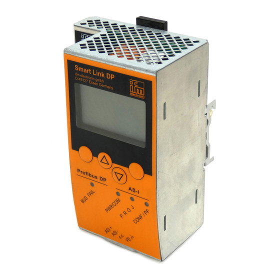
device manual AS-i DP - Gateway 4.2 AS-i diagnosis LEDs The three diagnosis LEDs on the front of the AS-i DP -Gateway give information concerning the state of the AS-i master and the connected AS-i system. The LEDs have the following meaning: ... - Page 10 device manual AS-i DP-Gateway After the voltage has been applied to both power supplies the AS-i DP -Gateway, the AS-i master and AS-i cable are supplied with power. The green LED 'PWR/COM‘ flashes if only the AS-i power supply and no slaves are connected to the system. Now slaves are to be addressed.
- Page 11 device manual AS-i DP - Gateway Choose the option "Change Address" and the desired AS-i master in the menu "Address Slave". The first slave which is detected (i.e. the slave with the lowest address) is displayed. Since in this case only one slave is connected the indicated address can only be that of this slave.
-
Page 12: Display Menu
device manual AS-i DP-Gateway 4.4 Display menu The four buttons of the AS-i DP -Gateway enable simple and fast working with the menu presentation in the display. The and buttons are used to select the menu or change the displayed values. Menus with more than three options are adapted automatically. - Page 13 device manual AS-i DP - Gateway System errors pertaining to AS-i DP -Gateway are displayed in a different way. They are immediately displayed when they occur and must be confirmed by pressing the right key. All possible system error messages are listed in the annex. F10: system error number 4-13...
-
Page 14: Menu Structure
device manual AS-i DP-Gateway 4.4.1 Menu structure Start display (AS-i Error Diagnostic) press ‚Menu‘ button Slave Lists: check the addresses of connected AS-i slaves See list of detected AS-i slaves (LDS) See list of projected AS-i slaves (LPS) See list of activated AS-i slaves (LAS) See list of periphery faults on AS-i slaves (LPF) ... -
Page 15: Profibus Dp Configuration
device manual AS-i DP - Gateway 5 Profibus DP configuration The AS-i DP -Gateway AC1325/AC1326 is a modular Profibus DP slave. To set up the Profibus DP slave address select the menu "field bus setup" in the AS-i DP -Gateway display. The new address is stored non volatilely in the device. - Page 16 device manual AS-i DP-Gateway The first module for example defines the number of binary I/O data bytes of single or A slaves of AS-i master 1 in the AS-i DP -Gateway which are to be transferred to the Profibus master via Profibus DP. The maximum data length of all 11 modules must not exceed 156 input bytes and 156 output bytes.
- Page 17 device manual AS-i DP - Gateway The AS-i master status information in the first byte of the digital inputs of the single /A slave data (byte 0, bit 4..7) contains the master flags of the respective AS-i system: Bit7 Bit6 Bit5 Bit4 reserved...
- Page 18 device manual AS-i DP-Gateway Module 4: Content: Only AC1326: binary inputs and outputs of B-slaves of AS-i master 2 Length: 0..16 Byte I/O (=0 if not used) Byte No. Bits 4..7 Bits 0..3 flags master 2 Slave1b Slave2b Slave3b Slave28b Slave29b Slave30b Slave31b...
- Page 19 device manual AS-i DP - Gateway Module 6: Note: If the analogue outputs are also driven by module 10 the output values of module 6 are overwritten by the values of module 10. Content: multiplexed analogue outputs of AS-i master 1 and 2 Length: 2 word consistent I/O (=0 if not used) DP master request:...
- Page 20 device manual AS-i DP-Gateway Command Description Byte 2 Byte 3 Byte 4 Get master flags MM000000 answer: MM000000 master flags Set operating mode MM000000 0 = Protected mode 1 = Config mode answer: MM000000 0 = Protected mode 1 = Config mode Get curr.slave config MMXSSSSS answer:...
- Page 21 device manual AS-i DP - Gateway Note: Two bits of the Command response byte indicate the state of the command channel: D7 = 1 -> Error during command processing D7 = 0 -> No error D6 = 1 -> Command being processed,channel busy. D6 = 0 ->...
- Page 22 device manual AS-i DP-Gateway Example command 3: read current slave configuration: DP Master Request: 1. Byte: 16#03 (command number) 2. Byte: 16#47 (AS-i Master 1, Slave Nr. 7) (AS-i master 1, slave no. 7) 3. Byte: 16#00 (not used) 4. Byte: 16#00 (not used) DP-Gateway Response: 1.
- Page 23 device manual AS-i DP - Gateway Example command 7, project slave parameters: Note: The projected parameters can only be changed if the AS-i master is in config mode! Please refer to command 2. DP Master Request: 1. Byte: 16#07 (command number) 2.
- Page 24 device manual AS-i DP-Gateway Example command 10, read LPF (List of Periphery Faults): DP Master Request: 1. Byte: 16#0A (command number) 2. Byte: 16#51 (AS-i master 1, slave no. 17, corresponds to slaves 16...31 = group 2) 3. Byte: 16#00 (not used) 4.
- Page 25 device manual AS-i DP - Gateway Example command 15, read AS-i cycle counter: DP Master Request: 1. Byte: 16#0F (command number) 2. Byte: 16#40 (AS-i master 1) 3. Byte: 16#00 (not used) 4. Byte: 16#00 (not used) DP-Gateway Response: 1. Byte: 16#0F (Copy of request) 2.
- Page 26 device manual AS-i DP-Gateway Example command 22, reset of slave error counter and configuration error counter: DP Master Request: 1. Byte: 16#16 (command number) 2. Byte: 16#40 (AS-i master 1) 3. Byte: 16#00 (not used) 4. Byte: 16#00 (not used) DP-Gateway Response: 1.
- Page 27 device manual AS-i DP - Gateway Example command 63, Null command without function: DP Master Request: 1. Byte: 16#3F (command number) 2. Byte: 16#00 (not used) 3. Byte: 16#00 (not used) 4. Byte: 16#00 (not used) DP-Gateway Response: 1. Byte: 16#3F 2.
-
Page 28: Device-Specific Profibus Dp Parameters
device manual AS-i DP-Gateway 5.1.2 Device-specific Profibus DP parameters: In order to define the addresses of the parallel analogue input and output slaves and to define parameters of the connected AS-i slaves, up to 100 byte device-specific parameters have to be set: Device-specific Profibus DP parameters (example): Byte 1..4: 16#80, 16#00, 16#00, 16#00, (fixed device parameter) -
Page 29: As-I Diagnostics
device manual AS-i DP - Gateway If this parameter ('Extended Profibus Diag.', byte 37 bit 5 TRUE) is changed to Enabled the AS-i DP- Gateway transfers the extended diagnosis data as described below. These data generate a DP diagnosis request in case of an error in the AS-i DP- Gateway. It is therefore necessary when using a Siemens PLC to program the block OB82 to detect this condition otherwise the PLC will be caused to stop. - Page 30 device manual AS-i DP-Gateway If as discussed above the parameter 'Extended Profibus Diag.' (byte 37 bit 5 TRUE) is set to Disabled (default condition) the AS-i DP- Gateway transmits no extended unit specific diagnostic data, only diagnostic data which every Profibus DP Slave is required to transmit(first 6 bytes). This is generally known as standard diagnostic.
-
Page 31: Reference
device manual AS-i DP - Gateway 6 Reference 6.1 Display messages In the AS-i DP Gateway display error messages are displayed in two different ways: 1. AS-i system error: The messages are displayed instead of the start image. There is no interruption in the menu handling, a flashing exclamation mark is displayed in the middle of the bottom line in the display instead (only if the configuration mode has been disabled) 2. - Page 32 device manual AS-i DP-Gateway slave 0 detected The master is in the “Protected Mode” and detects a slave with the address 0 on the AS-i line. This message is only generated if the profile of the missing slave on the AS-i line is identical with the detected one with the address 0.
-
Page 33: As-I Master Command Error
device manual AS-i DP - Gateway 6.1.2 AS-i master command error (code M01 ... M20 Error on command execution An error has occurred during the execution of an AS-i command which has stopped the execution of the command. More information will follow in another error message. slave not found The attempt was made to access a slave via an AS-i command which is not on the AS-i line, i.e. - Page 34 device manual AS-i DP-Gateway slave data invalid This error message has a multiple meaning and thus depends on the requested command: 1) slave readdressing Address 32 = 0B was indicated as target address. 2) Write parameters The attempt has been made to write a value greater than 0x7 to an A/B slave, ID=0xA. 7.4 slave toggle/sequence failure During transfer to the “7.4 slave protocol”...
-
Page 35: Flash Error (Code F00
device manual AS-i DP - Gateway 6.1.3 Flash error (code F00 ... F10) General flash failure This error message contains all unsuccessful operations which have to do with the integrated flash device. More details can be seen in the following error messages. Bad flash command The operating system has received an invalid command for the flash function block. -
Page 36: Timeout Error (Code T00
device manual AS-i DP-Gateway PLC write protection Not used in Profibus DP Gateway 6.1.4 Timeout error (code T00 ... T11) Timeout communication master The operating system has detected a timeout during communication with the master. Possible causes: Unacceptable interference on the 24V power supply. Unacceptable interference on the AS-i power supply. -
Page 37: Boot Error (Code B00
device manual AS-i DP - Gateway Timeout on master mode Unsuccessful change of the master into another operating mode, e.g. “Projection Mode”, “Protected Mode”. Possible cause: During change into the “Protected Mode” the master has detected a slave 0 and can thus not change into this operating mode. -
Page 38: Fat Error (Code F01
device manual AS-i DP-Gateway Exec. of PLC blocked by User When the device was started the automatic start of the plc program was automatically interrupted by the user. The left button of the button was activated during the switch-on operation. 6.1.6 FAT error (code F01 ... -
Page 39: General Rts Error (Code R01
device manual AS-i DP - Gateway General NV mirror switching During the change to the mirror range of the non-volatile data an error has occurred. Possible cause: Unacceptable interference on the 24V power supply cable during the storage operation of the data in the flash device. - Page 40 device manual AS-i DP-Gateway ASC0 handler switched The decoding of the serial data flow was switched over. Possible cause: Command within the serial data flow to switch over the device into the Test Mode / Normal Operating Mode. 24V power unstable During normal operation voltage dips below 18V were found on the 24V power supply cable.
- Page 41 device manual AS-i DP - Gateway DP parameter invalid The parameter setting of the Profibus master for the device is not valid. Possible causes: Setup of the parameter field is incorrect, length of the parameter field is not correct, the coding of the individual parameters corresponds to the possible settings.
-
Page 42: Hardware Error
device manual AS-i DP-Gateway 6.1.8 Hardware error ( --- exception error --- ) --- Exception Error --- STKOV: STKUN: Seg: Off: TFR: The main processor has detected an exception error. All current activities are interrupted. To exit this operating mode the device has to be switched off. The following entries in the TFR register give further details about the error cause: TFR Register D8 D7... -
Page 43: Technical Data
device manual AS-i DP - Gateway 6.2 Technical data General: Operating voltage AC1326: 20..30V DC (PELV) AC1335: 26,5...31,6 DC (AS-i) Current consumption AC1326: < 0.4A AC1335: < 0.2A Operating temperature 0..+60°C Storage temperature -20..+70°C Protection to DIN 40050 IP 20 Housing material aluminium Mounting... - Page 44 device manual AS-i DP-Gateway Index AS-i master setup ........4-14 Installation............ 1-4 AS-i slave address......4-10, 4-11 AS-i slave setup......... 4-14 LED '24V PWR‘..........3-6 LED CONF / PF ........... 4-9 Buttons............4-12 LED PROJ ........... 4-9 LED PWR/COM ........4-9, 4-10 Cabinet modules..........
Need help?
Do you have a question about the AS-i DP Series and is the answer not in the manual?
Questions and answers