Table of Contents
Advertisement
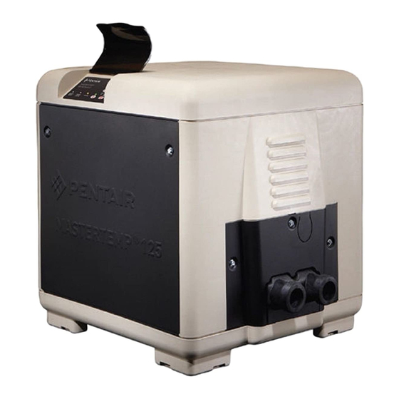
MASTERTEMP 125 POOL AND SPA HEATER (AUSTRALIA)
(FOR OUTDOOR USE ONLY*) INSTALLATION AND USER'S GUIDE
240 VAC NATURAL GAS/LP GAS
Model MT125
125K (33 kW) with cord
FOR YOUR SAFETY – This product must be installed
and serviced by authorized personnel, qualified in
pool/spa heater installation. Improper installation and/
or operation can create carbon monoxide gas and
flue gases which can cause serious injury, property
damage,or death. As an additional measure of safety,
Pentair Water Australia Pty. Ltd. strongly recommends
installation of suitable Carbon Monoxide detectors in
the vicinity of this heater. Improper installation and/or
operation will void the warranty.
Notice: MasterTemp Heaters are designed for use with NATURAL
and PROPANE gas only.
ATTENTION INSTALLER: PLEASE GIVE THIS MANUAL
TO THE OWNER AND/OR OPERATOR ONCE INSTALLATION
IS COMPLETE.
FOR YOUR SAFETY - READ BEFORE OPERATING
•
IF YOU DO NOT FOLLOW THESE INSTRUCTIONS EXACTLY, A FIRE OR EXPLOSION MAY RESULT,
CAUSING PROPERTY DAMAGE, PERSONAL INJURY OR LOSS OF LIFE.
•
IMPROPER INSTALLATION, ADJUSTMENT, ALTERATION, SERVICE OR MAINTENANCE CAN
CAUSE PROPERTY DAMAGE, PERSONAL INJURY OR DEATH. INSTALLATION AND SERVICE
MUST BE PERFORMED BY A QUALIFIED INSTALLER, SERVICE AGENCY OR THE GAS SUPPLIER.
•
DO NOT PLACE ARTICLES ON OR AGAINST THIS APPLIANCE.
•
DO NOT USE OR STORE FLAMMABLE MATERIALS NEAR THIS APPLIANCE.
•
DO NOT SPRAY AEROSOLS IN THE VICINITY OF THIS APPLIANCE WHILE IT IS IN OPERATION.
•
DO NOT TRY TO LIGHT ANY APPLIANCE.
•
DO NOT TOUCH ANY ELECTRICAL SWITCH; DO NOT USE ANY PHONE IN YOUR BUILDING.
•
IMMEDIATELY CALL YOUR GAS SUPPLIER FROM A NEIGHBOR'S PHONE.
FOLLOW THE GAS SUPPLIER'S INSTRUCTIONS.
•
IF YOU CANNOT REACH YOUR GAS SUPPLIER, CALL THE FIRE DEPARTMENT.
For additional free copies of this manual; call AUS: 1300 137 344 - NZ: 0800 654 112.
Pentair Water Australia Pty. Ltd.s AU/NZ – Head Office
1-21 Monash Drive, Dandenong South, Victoria 3175 – Australia • 1300.137.344 • Fax 1800.006.668
1620 Hawkins Ave., Sanford, NC 27330, USA • (919) 566-8000 • (800) 831-7133
10951 W. Los Angeles Ave., Moorpark, CA 93021, USA • (805) 553-5000 • (800) 831-7133
Natural
Propane
461092
461093
WHAT TO DO IF YOU SMELL GAS
www.pentairwater.com.au - www.pentair.com
(*) For heater indoor use, see page 21.
OWNER:
Retain For
Future
Reference
Advertisement
Table of Contents
Troubleshooting

Related Manuals for Pentair MT125


Summary of Contents for Pentair MT125
- Page 1 For additional free copies of this manual; call AUS: 1300 137 344 - NZ: 0800 654 112. Pentair Water Australia Pty. Ltd.s AU/NZ – Head Office 1-21 Monash Drive, Dandenong South, Victoria 3175 – Australia • 1300.137.344 • Fax 1800.006.668 1620 Hawkins Ave., Sanford, NC 27330, USA •...
-
Page 2: Heater Identification Information
4) Fuel Type : (LP = Propane gas or N = Natural gas) HEATER IDENTIFICATION INFORMATION — (HIN) H. I. N. HEATER IDENTIFICATION NUMBER ID DESIGNATOR FOR PENTAIR WATER POOL AND SPA MASTERTEMP™ 125 HEATER Example: = NATURAL GAS FUEL TYPE =... -
Page 3: Warning And Safety Information
MasterTemp 125 heater is a compact, lightweight, efficient, induced-draft, gas fired high performance pool and spa heater that can be directly connected to schedule 40 PVC pipe. The heater also comes equipped with the Pentair multifunction temperature controller which shows, at a glance, the proper functioning of the heater. All MasterTemp 125 heaters are ®... -
Page 4: Code Requirements
Warnings and Safety Instructions CODE REQUIREMENTS Installation must be in accordance with the following: DANGER CARBON MONOXIDE GAS IS DEADLY – Exhaust from this pool heater contains toxic levels of carbon monoxide, a dangerous, poisonous gas you cannot see or smell. DO NOT REMOVE Manufacturer’s Gas Installation Instructions S.A.A. - Page 5 Warning and Safety Instructions CONSUMER INFORMATION AND SAFETY (CONTINUED) WARNING The Consumer Product Safety Commission warns that carbon monoxide is an “invisible killer”. Carbon monoxide is a colorless and odorless gas. 1. Carbon monoxide is produced by burning fuel, including natural gas and propane. 2.
- Page 6 If used outdoors, install far from open windows, doors, vents and other openings. • Pentair strongly recommends that all vents, pipes and exhaust systems be initially and periodically tested for proper operation. This testing can be accomplished by using a hand-held carbon monoxide meter and/or by consulting with a gas professional.
- Page 7 Do not attempt to alter the rated input or type of gas by changing the orifice. If it is necessary to convert to a different type of gas, consult your Pentair dealer.
-
Page 8: Table Of Contents
Contents Customer Service If you have questions about ordering Pentair replacement parts, and pool products, please use the following contact information. Customer Service and Technical Support, AUS (9 AM - 5PM, Mon - Fri, Australia Wide) Phone: 1300 137 344... -
Page 9: General Specifications
Contents Contents (Continued) Section 1. Installation Instructions ................. (Continued) Electrical Connections ............................... Fireman’s Switch Connection/Remote Control Connections ................. MasterTemp 125 Heater Terminal Board/Control and Connection Wiring Diagram ..........Heater Bonding ................................ Connecting the MasterTemp Heater to the IntelliCenter Control System Load Center via RS-485 ......Connecting the RS-485 Cable from the Heater to the Load Center .............. -
Page 10: Section 1. Installation Instructions
This product must be installed and serviced by a professional service technician, qualified in pool heater installation. Pentair strongly recommends that all vents, pipes and exhaust systems be initially and periodically tested for proper operation. This testing can be accomplished by using a hand-held carbon monoxide meter and/or by consulting with a gas professional. -
Page 11: Specifications
Section 1. Installation Instructions SPECIFICATIONS (DIMENSIONS IN CENTIMETERS AND INCHES) These installation instructions are designed for use by qualified personnel only, trained especially for installation of this type of heating equipment and related components. Some states require installation and repair by licensed personnel. If this applies in your state, be sure your contractor bears the appropriate license. -
Page 12: Plumbing Connections
The low thermal mass of the heater will prevent overheating of the piping connected to the pump even if the heater shuts down unexpectedly. If you are using a flexible corrugated hose for above ground systems, use only Pentair approved flexible hose kits: P/N 155151 (1.8 cm - 6 ft.) and P/N 155005 (36.5 cm -12 ft.). -
Page 13: Multiple Heater Installation
Section 1. Installation Instructions MULTIPLE HEATER INSTALLATION All plumbing on multiple heater installations must be done in parallel. See Figure 5 and Figure 6. To prevent heater overheating and to ensure heater longevity, water flow to each heater must be balanced for optimum operation. -
Page 14: Valves
Section 1. Installation Instructions VALVES When any equipment is located below the surface of the pool or spa, valves should be placed in the circulation piping system to isolate the equipment from the pool or spa. Check valves are recommended to prevent back-siphoning. Back-siphoning is most likely to occur when the pump stops, creating a pressure-suction differential. -
Page 15: Automatic By-Pass
Section 1. Installation Instructions AUTOMATIC BY-PASS Figure 8 shows a plumbing diagram for an automatic BY-PASS (IntelliValve®). This in conjunction with an IntelliFlo VSF pump can provide added longevity of the heater and increased cost savings of operation. A 3-Port valve with an IntelliValve actuator is installed at the heater inlet. -
Page 16: Gas Connections
Section 1. Installation Instructions GAS CONNECTIONS GAS LINE INSTALLATIONS The gas supply must be installed in accordance with the Gas Installation Code, AS/NZS 5263.1.12:2019 and all applicable local codes. Before installing the gas line, be sure to check which gas the heater has been designed to burn. -
Page 17: Testing Gas Leaks And Pressure / Inlet Gas Pressure Requirements
Section 1. Installation Instructions TESTING GAS LEAKS AND GAS PRESSURE THE MASTERTEMP HEATER IS INTENDED FOR INSTALLATION WITH A METERED GAS PRESSURE REGULATOR. Before operating the heater, the heater and its gas connections must be leak tested. Do NOT use an open flame to test for leaks. Test all gas connections for leaks with soapy water. The gas valve must be completely disconnected from the gas supply piping system during any pressure testing of that system at test pressures in excess of 6.0 kPa. -
Page 18: Outdoor Heater Installation (Australia)
Section 1. Installation Instructions OUTDOOR HEATER INSTALLATION (AUSTRALIA) The following information is for heaters located outdoors, using the built-in stackless venting system. WARNING CARBON MONOXIDE GAS IS DEADLY – Exhaust from this pool heater contains carbon monoxide, a dangerous, poisonous gas you cannot see or smell. Symptoms of carbon monoxide exposure or poisoning include dizziness, headache, nausea, weakness, sleepiness, muscular twitching, vomiting and inability to think clearly. -
Page 19: Heater Clearances - Outdoor (Installation Venting Guidelines)
Section 1. Installation Instructions HEATER CLEARANCES – OUTDOOR IMPORTANT! • In an outdoor installation it is important to ensure water is diverted from overhanging eves with a proper gutter/drainage system. The heater must be set on a level foundation for proper drainage. •... - Page 20 Section 1. Installation Instructions WARNING Risk of fire and explosion. Do not spray aerosols in the vicinity of the heater while it is in operation. Chemicals should not be stored near the heater installation. Combustion air can be contaminated by corrosive chemical fumes which can damage the heater and will void the warranty.
-
Page 21: Indoor Venting - General Requirements
Section 1. Installation Instructions INDOOR VENTING — General Requirements NOTE: REMOVE OR COVER “OUTDOOR ONLY” LABEL LOCATED ON HEATER OUTSIDE PANEL WITH “INDOOR INSTALLATION” LABEL (P/N 474275) INCLUDED IN ACCESSORY BAG (P/N 473607). INDOOR INSTALLATION (SEE INSTALLATION GUIDE FOR CORRECT PLACEMENT OF THIS LABEL) If you are considering connecting this heater to a pre-existing vent system, make sure that the vent system meets the appropriate venting requirements as given in this manual on pages 22-32. -
Page 22: Vent Installation (Indoor Installation Or Outdoor Shelter)
Section 1. Installation Instructions VENT INSTALLATION – INDOOR INSTALLATION OR OUTDOOR SHELTER Flueing must be in accordance with AS/NZS 5263.1.12:2019 and local codes. Always vent the heater to the outdoors, see Note* below. Vent it vertically using double wall vent connector pipe. Locate the heater so as to minimize the length of horizontal venting and the number of vent elbows required. - Page 23 Table 4. – Permitted Minimum and Maximum Vent Heights By Size and Heater Model Double-Wall Vent with Double-Wall Connector in Meters (Feet) Vent Size MT125 - Height min./max. 150 mm (6 in.) 1.8 m (6 ft.) / 22 m (72 ft.) 200 mm (8 in.)
- Page 24 Section 1. Installation Instructions Table 5. – Maximum Number of Elbows per Vent Maximum Number of Elbows per Vent Lengths Maximum Elbows Total Vent Length Horizontal Maximum Vertical Vent Length Allowed (C=A+B) Vent Length 2m (6.6 ft.) 0.67m (2.2 ft.) 1.33m (4.4 ft.) 3m (9.8 ft.) 1m (3.3 ft.)
- Page 25 Section 1. Installation Instructions WARNING! Risk of fire or asphyxiation if vent is not assembled according to manufacturer’s instructions or if vent parts from different manufacturers are mixed. Vent parts from different manufacturers ARE NOT interchangeable. Mixing parts from more than one manufacturer may cause leaks or damage to vent.
-
Page 26: Horizontal Venting
Section 1. Installation Instructions HORIZONTAL VENTING The location of the flue terminal shall comply with the Australian standard. (See Figure 20): a) At least 300 mm below eaves, balconies and other projections. Chimney or Gas Vent Vent Cap and * Where eaves have openings into the house or roof space, Riser Furnished the clearance required is 1500 mm. -
Page 27: Horizontal Or Vertical Venting - Using Single-Wall Stainless Gas Vent
Section 1. Installation Instructions HORIZONTAL OR VERTICAL VENTING - USING SINGLE-WALL STAINLESS GAS VENT (SEE FIGURES 22, 23, & 24) Vent the heater either horizontally or vertically using an optional vent adapter of the 150 mm (6 in) or 102 mm (4 in) special gas approved stainless steel vent pipes. -
Page 28: Connecting Single-Wall Stainless Steel Vent To The Heater
CONNECTING SINGLE-WALL STAINLESS STEEL VENT TO THE HEATER Metallic: 1. Order an optional appliance adapter kit, (Pentair offers optional appliance adapter kits, call Customer Service) - Part No. 77707-0086 for Saf-T Vent or Saf-T Vent CI. - Part No. 77707-0087 for Z-Vent. - Page 29 Section 1. Installation Instructions Chimney or Gas Vent Chimney or Gas Vent Vent Cap and Vent Cap and Riser Furnished Riser Furnished by Installer by Installer Outlet Air Outlet Air Opening Opening Side Side Inlet Air Inlet Air Opening Wall Vent Wall Vent Opening Heater...
-
Page 30: Horizontal Or Vertical Venting Flexible Duct (Flex-Vent)
Section 1. Installation Instructions HORIZONTAL OR VERTICAL VENTING FLEXIBLE DUCT (FLEX-VENT) See Figures 22, 23 (page 29) and 25 NOTE: THE ALLOWABLE VENT RUNS FOR EACH VENT PIPE DIAMETER ARE DIFFERENT AND CAN NOT BE EXCEEDED. It is recommended that vent runs over 5.4 m (18 ft) may need to be insulated to reduce condensation related problems and/or the use of a condensate trap in the vent run close to the heater may be necessary in certain installations such as cold climates. -
Page 31: Combustion Air Supply
AS/NZS 5601.1 as applicable, and any local codes that may apply. These openings shall directly, or through duct, connect to outdoor air. Pentair does not recommend indoor installations that do not provide combustion air from outside the building. Air Supply Requirements Guide the MasterTemp 125 Heater... -
Page 32: Direct Air Intake Exhaust Duct Using 7.62 Cm (3 In) Pvc Pipe (Indoor Installation)
Section 1. Installation Instructions Direct Air Intake Duct with 7.62 cm (3 in) PVC Pipe (Indoor Installation) For indoor heater installations where combustion air supply might be insufficient, the MasterTemp 125 Heater is certified for a direct air intake duct using 7.62 cm (3 in) PVC pipe. If outside air is drawn through 7.62 cm (3in) PVC duct directly into the heater, PVC pipe can be installed in accordance with the following requirements: The air intake opening MUST be installed at least 1ft. -
Page 33: Control Panel Positioning
Section 1. Installation Instructions CONTROL PANEL POSITIONING On an outdoor shelter installation, the exhaust discharges into a vent pipe. Orient the heater so that the vent pipe does not interfere with adjustment of the operating controls. The control panel located on the top panel can be rotated to any of the three sides of the heater for easy access, see Figure 27. -
Page 34: Section 1. Installation Instructions (Continued)
Section 1. Installation Instructions ELECTRICAL CONNECTIONS Electrical Rating: 50 Hz 240 Volts AC, single phase: Enclose the incoming AC power line to the heater in an approved flexible conduit connected directly to the junction box on the inside of the access door panel. Line voltage field wiring should be 14 gauge, with a circuit capacity of 15 Amps. -
Page 35: Fireman's Switch Connection/Remote Control Connections
Section 1. Installation Instructions USE THE PROVIDED WATERPROOF WIRE NUTS WHEN CONNECTING THE POWER SUPPLY. A time clock controlling the filter pump should have a low-voltage Fireman’s Switch that switches off the heater at least 15 minutes before shutting off the pump. 1. -
Page 36: Heater Bonding
Section 1. Installation Instructions HEATER BONDING WARNING A bonding lug is provided on the heater located on the upper side of the base by the plumbing side (see Figure 32). The heater along with the pool system equipment must be bonded together. Using solid copper conductor not smaller then 8 AWG to reduce voltage gradients in the pool area. -
Page 37: Connecting The Mastertemp Heater To The Intellicenter Control System Load Center Via Rs-485
Section 1. Installation Instructions Connecting the MasterTemp Heater to the IntelliCenter™ Control System ® Load Center via RS-485 For remote control and monitoring, the MasterTemp heater can be connected via the heater’s RS-485 COM port to the IntelliCenter Control System COM port. The heater can be wired to the IntelliCenter Control System via a RS-485 connection. -
Page 38: Connecting The Rs-485 Cable From The Heater To The Load Center
Section 1. Installation Instructions Connecting the RS-485 Cable from the Heater to the Load Center To connect the MasterTemp heater to the load center: BEFORE REMOVING THE HIGH VOLTAGE COVER PANEL FROM THE LOAD CENTER OR POWER CENTER ENCLOSURE SWITCH OFF THE POWER AT THE HOUSE MAIN CIRCUIT BREAKER BOX. - Page 39 Section 1. Installation Instructions Connecting the RS-485 Cable from the Heater to the Load Center (Continued) Note: COM PORT A& B 14 VDC, 2.0A Max. Combined +15 +DT -DT GND COMMUNICATION PORTS A & B 14 VDC, 2.0A Max. Combined. ®...
-
Page 40: Heater Wiring Diagram (3-Wire System)
Section 1. Installation Instructions HEATER WIRING DIAGRAM (3-WIRE SYSTEM) Figure 37. MASTERTEMP 125 Pool and Spa Heater Installation and User’s Guide 460906 Rev. D 8/2020... -
Page 41: Heater Electrical Schematic Ladder Diagram
Section 1. Installation Instructions HEATER ELECTRICAL SCHEMATIC LADDER DIAGRAM BYPASS VALVE 4.) EXTERNAL VALVE THAT NEEDS TO BE INSTALLED. Figure 38. 460906 Rev. D 8/2020 MASTERTEMP 125 Pool and Spa Heater Installation and User’s Guide... -
Page 42: Section 2. Operations
Section 2. Operations Operations BASIC SYSTEM OPERATION Start pump, make sure the pump is running and is primed, to close the water pressure switch and supply power to heater. Be sure the pool and/or spa is properly filled with water. Follow the Lighting/Operating instructions below. HEATER HSI ELECTRONIC IGNITION LIGHTING/OPERATION FOR YOUR SAFETY: READ BEFORE LIGHTING WARNING If you do not follow these instructions exactly, a fire or explosion may result causing property damage, personal injury or loss of life. -
Page 43: Operating Instructions
Section 2. Operations OPERATING INSTRUCTIONS 1. STOP! Read the safety information on page 42. 2. Set both pool and spa thermostats to the lowest settings. Water 3. Turn off all electric power to the appliance. Turn OFF the Manual Pressure Switch Shut-Off Valve, see Figure 40. -
Page 44: Safety Controls/Air Flow Switch (Afs)
Section 2. Operations SAFETY CONTROLS AIR FLOW SWITCH (AFS) The air flow switch, (see Figure 42), is a safety device used to insure that the combustion air blower (fan) is operating and has been designed to monitor the vacuum (negative) pressure within the blower housing. -
Page 45: Operation Of Ignition Module (Icm)
Section 2. Operations SAFETY CONTROLS (continued) OPERATION OF IGNITION MODULE , see Figure 45, The Ignition Module is microprocessor based and operates on 24VAC supplied by the transformer. The control utilizes a microprocessor to continually and safely monitor, analyze, and control the proper operation of the gas flame holder. -
Page 46: Control Panel
Section 2. Operations CONTROL PANEL Pool/Spa LCD Temperature Toggle Button Display Control Panel Description The LCD displays two lines of text. During LCD Display: normal heater operation the current pool or spa water temperature is shown on line 1 of the display. The heater set point for the pool or spa is shown on line 2 of the display. -
Page 47: Menu
Section 2. Operations Menu The maximum heater operating temperature for the pool. POOL MAX (65°F-104°F): The maximum heater operating temperature for the spa. SPA MAX (65°F-104°F): Select F (Fahrenheit) or C (Celsius) to display change the display of the heat settings. Select US or Metric units. UNITS: Use Up/Down button to scroll through the last five heater errors. -
Page 48: Section 3. Troubleshooting
Section 3. Troubleshooting Troubleshooting Initial Troubleshooting Only qualified, trained service technicians with appropriate test equipment should service the heater. Remember that all parts of the system affect heater operation. Before starting this troubleshooting procedure, make sure that the pump is running correctly, that there are no blockages in the system, that the valves are correctly set and that the time clock is correctly set and is running. -
Page 49: Initial Troubleshooting / Error And Fault Codes
Section 3. Troubleshooting Error and Fault Codes Table 8. Heater Error and Fault Codes Fault Condi�on Error Code Note Troubleshoo�ng Displayed Water pressure switch ERR PS If water flow is established the No water flow thru open the error is cleared and normal heater opera�on is resumed. -
Page 50: Troubleshooting Instruction
Section 3. Troubleshooting Troubleshooting Instruction Initial Troubleshooting Only qualified, trained service technicians with appropriate test equipment should service the heater. Remember that all parts of the system affect heater operation. Before starting this troubleshooting procedure, make sure that the pump is running correctly, that there are no blockages in the system, that the valves are correctly set and that the time clock is correctly set and is running. -
Page 51: Heater Will Not Fire - A
Section 3. Troubleshooting Heater Will Not Fire - A Start Press Pool/Spa button on Heater should fire on demand Is POOL or SPA for heat. pad. Does POOL or SPA displayed on the LCD? displays on LCD? Check that correct 12-pin Check for line voltage to Restore power to heater. -
Page 52: Heater Will Not Fire - B
Section 3. Troubleshooting Heater Will Not Fire - B Start Is ERR PS displayed on LCD? Verify that pump is on, filter is not blocked, and the water flow is above the minimum requirement. Service pump/filter and elimi- nate other flow obstructions. With pump running, adjust Water Pressure Switch to lower pressure until ERR PS... -
Page 53: Ign Is On
Section 3. Troubleshooting IGN is ON ALARMS: AGS, AFS, HLS, PS, E01 or 126 Gas flow during ignition and Verify connection to HSI igniter, burner fire for less than 7 seconds. HSI is not broken, flame current status. Gas flow during ignition try, but burner does not fire. -
Page 54: Diagnostic Alarms: Ags, Afs, Hls, Ps, Eo1, Or 126
Section 3. Troubleshooting Diagnostic Alarms: AGS, AFS, HLS, PS, E01 or 126 ERR AGS or Verify that water flow rate is Service pump and filter to above minimum required for restore proper flow. After ser- ERR HLS heater. vicing, verify proper operation Replace High Limit of Pressure Switch (PS). -
Page 55: Diagnostic Alarms: Err Sfs
Section 3. Troubleshooting Diagnostic Alarms: SFS ERR SFS Check Heat Exchanger Coil for leaks, liming, soot, or low flow. Heater starts and runs OK, but temperature of exhaust climbs to 450°–500° in 3–5 Check Thermal minutes. Regulator: Open at 120°? Replace Heater (HD ) Membrane Pad. -
Page 56: Burner Troubleshooting
Section 3. Troubleshooting Burner Troubleshooting SYMPTOM CAUSE REMEDY Loud, high-pitched whine Flame is too rich. Verify pressure tap between gas valve and blower inlet. See page 17 and verify that the gas regulator setting is –0.2" (–0.5cm) wc. Contact a qualified technician or service agency to replace the gas orifice. -
Page 57: Section 4. Maintenance
Section 4. Maintenance Maintenance Instructions WARNING Risk of fire or explosion from flammable vapors. Do not store gasoline, cleaning fluids, varnishes, paints, CARE AND MAINTENANCE or other volatile flammable liquids near heater or in the same room with heater. WARNING DO NOT interfere with any sealed components. -
Page 58: After Start-Up Checking Water Flow
Section 4. Maintenance AFTER START-UP CHECKING WATER FLOW WARNING Fire or flooding hazard. If the unit overheats and the burner fails to shut off, follow instructions under “To Turn Off Gas to the Appliance”, page 43, and call a qualified service technician to repair unit. After start-up, the outlet water pipe should feel slightly warmer than the inlet pipe. -
Page 59: Maintaining Pool Temperature
Section 4. Maintenance MAINTAINING POOL TEMPERATURE To maintain pool temperature, make sure that the heater switch and valving are reset to pool settings after using the spa. ENERGY SAVING TIPS 1. Keep the pool or spa covered when not in use. This will reduce heating costs, reduce water evaporation, conserve chemicals and reduce load on the filtering system. -
Page 60: Chemical Balance
Section 4. Maintenance CHEMICAL BALANCE (continued) It is wise to test pool water regularly. Never allow chlorine residual to drop below 0.6 ppm (parts per million). The minimum level for effective chlorine or bromine residual is 1.4 ppm. pH - The term pH refers to the acid/alkaline balance of water expressed on a numerical scale from 0 to 14. A test kit for measuring pH balance of your pool water is available from your local pool supply store;... -
Page 61: Section 5. Replacement Parts
(Key Nos. 1 through 4), See Page 65. Repair Parts are available from your Pentair dealer. If your dealer cannot supply you, call Customer Support at 1-800-831-7133. 460906 Rev. D 8/2020 MASTERTEMP 125 Pool and Spa Heater Installation and User’s Guide... - Page 62 Section 5. Replacement Parts MasterTemp 125 HEATER REPLACEMENT PARTS ® MASTERTEMP 125 Pool and Spa Heater Installation and User’s Guide 460906 Rev. D 8/2020...
- Page 63 Section 5. Replacement Parts MASTERTEMP 125 HEATER REPLACEMENT PARTS ® REPAIR PARTS – BURNER SYSTEM Model Part MT125 NA Qty. MT125 LP Description 42001-0051S Combination Gas Control Valve Kit 3/4" Union 38404-4097S Gas Orifice Gas Orifice O-Ring • Gas Orifice Kit – NG (Incl. Key Nos. 3 and 4)†...
- Page 64 Section 5. Replacement Parts MASTERTEMP 125 HEATER REPLACEMENT PARTS ® REPAIR PARTS – WATER SYSTEM Model Part MT125 NA Description MT125 LP Qty. Tube Sheet Coil Assembly Kit (NA, LP) (Includes Key No.3) 474971 M anifold Kit (Includes Key Nos. 3-11.
- Page 65 Section 5. Replacement Parts MASTERTEMP 125 HEATER REPLACEMENT PARTS ® REPAIR PARTS – ELECTRICAL SYSTEM Part MT125 HD NA & LP Model 125 (NA/LP) Description Qty. (*) International Heater Display Cover 42002-0035 Igniter Bracket 42001-0030S Igniter/Igniter Gasket Kit Incl. Key Nos. 3 and 4)
- Page 66 NOTES MASTERTEMP 125 Pool and Spa Heater Installation and User’s Guide 460906 Rev. D 8/2020...
- Page 67 NOTES 460906 Rev. D 8/2020 MASTERTEMP 125 Pool and Spa Heater Installation and User’s Guide...
- Page 68 Australia • 1300.137.344 • Fax 1800 006.668 www.pentair.com.au All indicated Pentair trademarks and logos are property of Pentair Inc. or its global affiliates in the U.S.A. and/or other countries. Third party registered and unregistered trademarks and logos are the property of their respective owners ©...
Need help?
Do you have a question about the MT125 and is the answer not in the manual?
Questions and answers