
Related Manuals for Pressure Tech Swiss PT-1000


Summary of Contents for Pressure Tech Swiss PT-1000
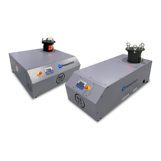
- Page 1 PressureTech Swiss Series High Pressure Coolant Pumps Models: PT-1000, PT-2000 OPERATION MANUAL PT-1000-H PT-2000 PressureTech New England Tool Corp. 161 Sanrico Drive Perfection Under Pressure Manchester, CT 06042...
-
Page 2: Table Of Contents
Table of Contents Safety Instructions ....................pg. 3 Operation ....................pg. 4 Maintenance Schedule ....................pg. 6 HMI Navigation ....................pg. 7 Alarms ....................pg. 8 Alarm Codes ....................pg. 9 Parameters ....................pg. 11 Electrical Diagram ....................pg. 12 Elec. -
Page 3: Safety Instructions
SAFETY INSTRUCTIONS • Make sure electrical power is disconnected before servicing the high pressure pump or electrical cabinet. • Do not move high pressure pump while it is powered on. • For maintenance purposes, only use parts provided or recommended by PressureTech and New England Tool Corporation. -
Page 4: Operation
OPERATION FILTER SYSTEM START-UP PROCEDURE Prior to turning on the flow to the inlet service, please complete the following checks: 1. Check inside the filter unit to be sure the basket and filter bag (if applicable) are in the housing and do not require cleaning or replacement. - Page 5 4. Drain housing sufficiently to access filter basket. 5. Remove cover by loosening the T-bolt clamp sufficiently to allow removal of the clamp assembly. 6. Remove filter basket and clean thoroughly, remove the filter bag (if applicable) and throw away. (Cleaning and reusing the filter bag is not recommended.) 7.
-
Page 6: Maintenance Schedule
MAINTENANCE SCHEDULE DAILY Periodically monitor the pressure on the HMI home screen to be certain the inlet pressure remains positive. If the filter is clogged, the unit will trip an alarm for maintenance. A negative inlet pressure is a sign that the filter bag needs to be changed. We recommend using a 5 micron bag filter, a less fine filter will let unwanted particles pass through and possibly damage the pump. -
Page 7: Hmi Navigation
HMI NAVIGATION ITEM NAME FUNCTION PUMP PRESSURE Displays the current outlet pressure from the pump in either PSI or BAR depending on the value of parameter 106. FILTER PRESSURE Displays the current filter pressure in either PSI or BAR depending on the value of parameter 106. -
Page 8: Alarms
ALARMS ITEM NAME FUNCTION ALARM DISPLAY Displays the test associated with an alarm or warning that has occurred. ALARM RESET Pressing this button will only clear alarms for which the root cause has been corrected. ALARM PAGE NAVIGATION Use these buttons to navigate through all displayed alarms. ALARM HISTORY Pressing this button takes you to the alarm history page. -
Page 9: Alarm Codes
ALARM CODES CODE NAME CAUSE RESOLUTION E-STOP PRESSED THE E-STOP PUSHBUTTON ON RELEASE THE E-STOP ON THE THE UNIT IS PRESSED UNIT PUMP HIGH PRESSURE THE PUMP PRESSURE HAS CHECK TO MAKE SURE THERE EXCEEDED THE ALLOWABLE ARE NO BLOCKAGES IN THE THRESHOLD INPUT INTO PARAM- FLUID PATH;... - Page 10 CODE NAME CAUSE RESOLUTION BOOSTER PUMP CON- THE BOOSTER PUMP IS BEING CALL PRESSURETECH FOR TACTOR MALFUNCTION TOLD TO RUN AND IS NOT RUN- REPLACEMENT PARTS NING, OR THE PUMP IS BEING TOLD TO STOP RUNNING AND IS CONTINUING TO RUN COOLING FAN MOTOR THE CIRCUIT BREAKER FOR THE ENSURE THAT THE FAN IS ABLE...
-
Page 11: Parameters
PARAMETERS NUMBER NAME DESCRIPTION DEFAULT RANGE PUMP ON DELAY THE VALUE ENTERED (SECONDS) IS THE 0.0 - 10.0 TIME THAT THE PUMP WILL DELAY TURNING ON AFTER THE VALVE IS TURNED ON. VALVE CLOSE DELAY THE VALUE ENTERED (SECONDS) IS THE 0.0 - 10.0 TIME THAT THE VALVES WILL DELAY CLOS- ING AFTER THE PUMP IS TURNED OFF. -
Page 12: Electrical Diagram
ELECTRICAL DIAGRAM ***Please See Appendix*** Operation Manual for PT-1000 & PT-2000 Page 12... -
Page 13: Elec. Panel Assembly
ELECTRICAL PANEL ASSEMBLY ITEM # PART # DESCRIPTION QUANTITY 300142 END STOP, DIN RAIL MOUNT 300090 DPST 24DC RELAY 1.5x1x12 WIDE SLOT WIRING DUCT 1.5x1x22.75 WIRE DUCT DIN RAIL_21in DIN RAIL, SLOT PATTERN 300420 GROUND TERMINAL BLOCK, 10MM 1X1060001 3-POLE TERMINAL, 10MM 1X1040001 WDR-120 SERIES, 120W DIN RAIL, 24VDC 300137... -
Page 14: Elec. Panel For "H" Assembly
ELECTRICAL PANEL FOR “H” ASSEMBLY ITEM # PART # DESCRIPTION QUANTITY 300090 DPST 24VDC RELAY 1X1040001 WDR-120 SERIES, 120 WATT DIN RAIL 24VDC 1X1010016 X20 DIGITAL 12XI, 24V, SINK, 1 WIRE 1X1010008 X20 BUS TRANSMITTER, FEED 24 V, X67 SUPPLY 1X1010020 X2X BUS RECEIVER 1X1010022... -
Page 15: Sheet Metal Assembly
SHEET METAL ASSEMBLY ITEM # PART # DESCRIPTION QUANTITY 1X3004001 BASE PLATE 1X3004010 ELECTRICAL ENCLOSURE 1X3004003 BACK COVER 1X3004002 FRONT COVER 1X3004017 ELECTRICAL PANEL BACKPLATE 1X3004004 RIGHT SIDE COVER 1X3004009 ELECTRICAL PANEL COVER 1X3002014 1’’ MOUNTING BRACKET 1X3004008 LEFT SIDE COVER 1X3006009 REAR FILTER COVER 1X3006010... -
Page 16: Sheet Metal For "H" Assembly
SHEET METAL FOR “H” ASSEMBLY ITEM # PART # DESCRIPTION QUANTITY 1X3006001 BASE PLATE 1X3006002 ELECTRICAL ENCLOSURE 1X3006005 FRONT COVER 1X3006006 REAR COVER 1X3006004 ELECTRICAL COVER 1X3006008 ELECTRICAL ACCESS PANEL 1X3006009 REAR FILTER COVER 1X3006010 FRONT FILTER COVER 1X3006003 HYDRAULIC COVER 1X3006007 TOP COVER 1X3006011... -
Page 17: 1000 Motor Assembly
1000 MOTOR ASSEMBLY ITEM # PART # DESCRIPTION QUANTITY 510001 5HP MOTOR, 1760 RPM, 4 POLE 710002 MOTOR TO PUMP ADAPTER 710004 SPIDER LOVEJOY 1-1/8 710005 LOVEJOY SPIDER 710003 SPIDER LOVEJOY 5/8 510002 GEAR PUMP 8 GPM 610001 5/8" MPT O'RING X 1/2" MJIC ELBOW 610002 3/4"... -
Page 18: 1000-W Motor Assembly
1000-W MOTOR ASSEMBLY ITEM # PART # DESCRIPTION QUANTITY 5200022 5HP MOTOR, 1150 RPM, 6 POLE 530002 8.8 GPM DIAPHRAGM PUMP 520003-1 BOWEX M-38 COUPLING 520003-2 BOWEX MOTOR GEAR 520003-3 BOWEX PUMP GEAR 530001 MOTOR PUMP ADAPTER 610026 1" MALE X .75" FEMALE BRASS BUSHING 620006 3/4"... -
Page 19: 2000 Motor Assembly
2000 MOTOR ASSEMBLY ITEM # PART # DESCRIPTION QUANTITY 610001 5/8" MPT O'RING X 1/2" MJIC ELBOW 710007 MOTOR TO PUMP ADAPTER 610002 3/4" MPT O'RING X 3/4" FPT STREET ELBOW 1X2040006 3/4" MPT X 1" MJIC STRAIGHT 520001 7.5 HP MOTOR 710006 SPIDER LOVEJOY 1-3/8"... -
Page 20: Booster Pump Assembly
VALVE MANIFOLD ASSEMBLY ITEM # PART # DESCRIPTION QUANTITY 510003 MAIN MANIFOLD BLOCK 7100013 PRESSURE RELIEF VALVE 610006 1/2" O'RING PLUG 1X2040007 1/2" MNPT X 3/4" MJIC 90° ELBOW 610010 1/2" O'RING M X 1/2" JIC F SWIVEL 880001 SOLENOID VALVE 880002 24VDC SOLENOID VALVE COIL 1X1080002... -
Page 21: Valve Manifold Assembly
HEAT EXCHANGER ASSEMBLY ITEM # PART # DESCRIPTION QUANTITY 200011 HEAT EXCHANGER 620002 1" MNPT x 3/4" FNPT COUPLING 1X2040003 3/4" MNPT STEEL BRANCH TEE 1X2040004 3/4" MNPT x 1" MJIC ELBOW 620066 3/4" MNPT X 1" MJIC ELBOW Operation Manual for PT-1000 & PT-2000 Page 21... -
Page 22: Filter Assembly
FILTER ASSEMBLY ITEM # PART # DESCRIPTION QUANTITY 510011 FILTER VESSEL 610018 BRASS BALL VALVE, 3/4" FNPT 1X2040004 3/4" MNPT X 1" MJIC ELBOW 1X1030001 -1 TO 2 BAR PRESSURE XMTR, 0-10VDC, 610016 1/4" MNPT X FNPT GAUGE COCK 1X2040006 3/4"... - Page 23 BOOSTER PUMP ASSEMBLY ITEM # PART # DESCRIPTION QUANTITY 720002 1/3 HP BOOSTER PUMP 1X2040004 1/3 HP BOOSTER PUMP 1X2040006 3/4" MPT X 1" MJIC STRAIGHT Operation Manual for PT-1000 & PT-2000 Page 23...
-
Page 24: Warranty
WARRANTY PressureTech warrants that within 12 months from original shipment, if its products are operated by the original specified user: PressureTech will repair or replace, at its option, free of charge except freight, FOB shipping point, any parts it finds nonconforming on these conditions: •... - Page 25 New England Tool Corp. 161 Sanrico Drive Manchester, CT 06042 tel.: 860-783-5555 fax: 860-783-5552 email: sales@pressuretechsystems.com www.PressureTechSystems.com...
- Page 26 New England THIS DRAWING IS THE PROPERTY OF NEW ENGLAND TOOL CORP AND INFORMATION M:\Logos\NETC_Crest.jpg Tool Corporation HEREON IS CONFIDENTIAL AND MUST NOT BE REPRODUCED OR REVEALED TO TITLE: HIGH VOLTAGE - USA VERSION UNAUTHORIZED PERSONS OR SENT OUTSIDE THE COMPANY WITHOUT PROPER AS BUILT 02/27/18 DRAWN:...
- Page 27 New England THIS DRAWING IS THE PROPERTY OF NEW ENGLAND TOOL CORP AND INFORMATION M:\Logos\NETC_Crest.jpg Tool Corporation HEREON IS CONFIDENTIAL AND MUST NOT BE REPRODUCED OR REVEALED TO TITLE: HIGH VOLTAGE - EUROPEAN VERSION UNAUTHORIZED PERSONS OR SENT OUTSIDE THE COMPANY WITHOUT PROPER AS BUILT 02/27/18 DRAWN:...
- Page 28 New England THIS DRAWING IS THE PROPERTY OF NEW ENGLAND TOOL CORP AND INFORMATION M:\Logos\NETC_Crest.jpg Tool Corporation HEREON IS CONFIDENTIAL AND MUST NOT BE REPRODUCED OR REVEALED TO TITLE: 24VDC POWER DISTRIBUTION UNAUTHORIZED PERSONS OR SENT OUTSIDE THE COMPANY WITHOUT PROPER AS BUILT 02/27/18 DRAWN:...
- Page 29 New England THIS DRAWING IS THE PROPERTY OF NEW ENGLAND TOOL CORP AND INFORMATION M:\Logos\NETC_Crest.jpg Tool Corporation HEREON IS CONFIDENTIAL AND MUST NOT BE REPRODUCED OR REVEALED TO TITLE: RACK 1 SLOT 1 UNAUTHORIZED PERSONS OR SENT OUTSIDE THE COMPANY WITHOUT PROPER AS BUILT 02/27/18 DRAWN:...
- Page 30 New England THIS DRAWING IS THE PROPERTY OF NEW ENGLAND TOOL CORP AND INFORMATION M:\Logos\NETC_Crest.jpg Tool Corporation HEREON IS CONFIDENTIAL AND MUST NOT BE REPRODUCED OR REVEALED TO TITLE: RACK 1 SLOT 2 UNAUTHORIZED PERSONS OR SENT OUTSIDE THE COMPANY WITHOUT PROPER AS BUILT 02/27/18 DRAWN:...
- Page 31 New England THIS DRAWING IS THE PROPERTY OF NEW ENGLAND TOOL CORP AND INFORMATION M:\Logos\NETC_Crest.jpg Tool Corporation HEREON IS CONFIDENTIAL AND MUST NOT BE REPRODUCED OR REVEALED TO TITLE: RACK 1 SLOT 3 UNAUTHORIZED PERSONS OR SENT OUTSIDE THE COMPANY WITHOUT PROPER AS BUILT 02/27/18 DRAWN:...
- Page 32 New England THIS DRAWING IS THE PROPERTY OF NEW ENGLAND TOOL CORP AND INFORMATION M:\Logos\NETC_Crest.jpg Tool Corporation HEREON IS CONFIDENTIAL AND MUST NOT BE REPRODUCED OR REVEALED TO TITLE: RACK 1 SLOT 4 UNAUTHORIZED PERSONS OR SENT OUTSIDE THE COMPANY WITHOUT PROPER AS BUILT 02/27/18 DRAWN:...
- Page 33 New England THIS DRAWING IS THE PROPERTY OF NEW ENGLAND TOOL CORP AND INFORMATION M:\Logos\NETC_Crest.jpg Tool Corporation HEREON IS CONFIDENTIAL AND MUST NOT BE REPRODUCED OR REVEALED TO TITLE: UNAUTHORIZED PERSONS OR SENT OUTSIDE RACK 1 SLOT 5 THE COMPANY WITHOUT PROPER AS BUILT 02/27/18 AUTHORIZATION FROM NEW ENGLAND TOOL...
- Page 34 New England THIS DRAWING IS THE PROPERTY OF NEW ENGLAND TOOL CORP AND INFORMATION M:\Logos\NETC_Crest.jpg Tool Corporation HEREON IS CONFIDENTIAL AND MUST NOT BE REPRODUCED OR REVEALED TO TITLE: RACK 1 SLOT 6 UNAUTHORIZED PERSONS OR SENT OUTSIDE THE COMPANY WITHOUT PROPER AS BUILT 02/27/18 DRAWN:...
- Page 35 New England THIS DRAWING IS THE PROPERTY OF NEW ENGLAND TOOL CORP AND INFORMATION M:\Logos\NETC_Crest.jpg Tool Corporation HEREON IS CONFIDENTIAL AND MUST NOT BE REPRODUCED OR REVEALED TO TITLE: UNAUTHORIZED PERSONS OR SENT OUTSIDE X67 NODE 1 THE COMPANY WITHOUT PROPER AS BUILT 02/27/18 AUTHORIZATION FROM NEW ENGLAND TOOL...
- Page 36 New England THIS DRAWING IS THE PROPERTY OF NEW ENGLAND TOOL CORP AND INFORMATION M:\Logos\NETC_Crest.jpg Tool Corporation HEREON IS CONFIDENTIAL AND MUST NOT BE REPRODUCED OR REVEALED TO TITLE: UNAUTHORIZED PERSONS OR SENT OUTSIDE THE COMPANY WITHOUT PROPER AS BUILT 02/27/18 DRAWN: DATE:...
Need help?
Do you have a question about the Swiss PT-1000 and is the answer not in the manual?
Questions and answers