
Related Manuals for Pressure Tech Turret Series


Summary of Contents for Pressure Tech Turret Series
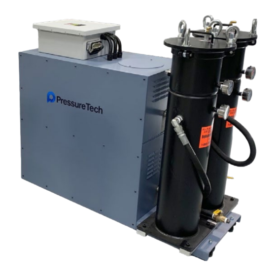
- Page 1 PressureTech Turret Series High Pressure Coolant Pumps Models: EU-1000, EU-1000-2 MAINTENANCE MANUAL EU-1000-2 EU-1000 PressureTech New England Tool Corp. 161 Sanrico Drive Perfection Under Pressure Manchester, CT 06042...
-
Page 2: Table Of Contents
Table of Contents Safety Instructions ....................pg. 3 Operation ....................pg. 4 Maintenance Schedule ....................pg. 6 Electrical Diagram ....................pg. 7 Sheet Metal Assembly ....................pg. 8 Motor Assembly ....................pg. 10 Valve Assembly ....................pg. 11 Left Filter Assembly .................... -
Page 3: Safety Instructions
SAFETY INSTRUCTIONS • Make sure electrical power is disconnected before servicing pressure pump or electrical cabinet. • Do not move high pressure pump while it is powered on. • For maintenance purposes, only use parts provided or recommended by PressureTech and New England Tool Corporation. -
Page 4: Operation
OPERATION FILTER SYSTEM START-UP PROCEDURE Prior to turning on the flow to the inlet service, please make the following checks: 1. Check inside filter unit to be sure basket and filter bag (if applicable) are in housing and do not require cleaning or replacement. - Page 5 SPARE PARTS (FOR MAINTENANCE) Your PressureTech Turret Series unit will give you many years of reliable service provided periodic inspections are made of various components and replacement of worn parts are made promptly. The following is meant to be a recommended spare parts list, these parts are illustrated on the following page.
-
Page 6: Maintenance Schedule
MAINTENANCE SCHEDULE DAILY Check the pressure difference between input and output gauges on the filter body (part # 610027). Pressure difference should not be greater than 5 PSI while the unit is in operation, anything over this indicates the bag may need to be replaced. UNDER NO CIRCUMSTANCES should the output gauge should read negative pressure (vacuum) as that condition might cause pump to fail. -
Page 7: Electrical Diagram
ELECTRICAL DIAGRAM ***Please See Appendix*** PART NUMBER DESCRIPTION QUANTITY 300007 MAIN DISCONNECT SWITCH 300113 CONTACTOR AC-3 16 A, 7.5 kW / 400V 1 NO, 24V DC 300063 O.L. RELAY 300015 MTR PROT. CB COMBINATION PT-CABLE-16-V1 20' LONG SIGNAL CABLE 990012 ELECTRICAL BOX Maintenance Manual for EU-1000 &... -
Page 8: Sheet Metal Assembly
SHEET METAL ASSEMBLY ITEM # PART # DESCRIPTION QUANTITY EU-1000_920001-1 BASE PLATE EU-1000_920001-2 TOP BASE PLATE EU-1000-920001-3 BLANK SIDE COVER EU-1000-940004 FRONT COVER EU-1000-920001-5 PUMP FILL COVER Maintenance Manual for EU-1000 & EU-1000-2 Page 8... - Page 9 SHEET METAL ASSEMBLY ITEM # PART # DESCRIPTION QUANTITY EU-1000-2_501_BASE BASE PLATE EU-1000-2_501B_TOP_BASE TOP BASE PLATE EU-1000-2_507_UPRIGHT VERTICAL SUPPORT EU-1000-2_508_UPRIGHT-END5 VERTICAL SUPPORT CAP EU-1000-2_503_BODY TOP WRAP AROUND COVER EU-1000-2_510-BOTTOM-RIGHT-PANEL FRONT COVER EU-1000-2_511-BOTTOM-LEFT-PANEL REAR COVER EU-1000-2_516_REAR_PANEL BLANK SIDE COVER EU-1000-2_515_FRONT_PANEL HYDRAULIC SIDE COVER FILTER SUPPORT FILTER SUPPORT BRACKET EU-1000-2_517_FILLCOVER...
-
Page 10: Motor Assembly
MOTOR ASSEMBLY ITEM # PART # DESCRIPTION QUANTITY 520002 5 HP MOTOR, 1150 RPM, 6 POLE 530002 8.8 GPM DIAPHRAM PUMP 520003-1 BOWEX M-38 COUPLING 520003-2 BOWEX MOTOR GEAR 520003-3 BOWEX PUMP GEAR 530001 MOTOR PUMP ADAPTER 610026 1" MALE X .75" FEMALE BRASS BUSHING 620006 3/4"... -
Page 11: Valve Assembly
VALVE MANIFOLD ASSEMBLY ITEM # PART # DESCRIPTION QUANTITY 610020 PRESSURE GAUGE 510007 MANIFOLD BLOCK 710001 PRESSURE RELIEF VALVE 630070 1/2 NPT X 6" PIPE NIPPLE 880001 SOLENOID VALVE 880002 24VDC SOLENOID VALVE COIL 1X1080002 24VDC SOLENOID ELECTRICAL CABLE 610008 1/2"... -
Page 12: Left Filter Assembly
LEFT FILTER ASSEMBLY ITEM # PART # DESCRIPTION QUANTITY 510005 FILTER VESSEL 610016 SHUTOFF VALVE 610027 PRESSURE GAUGE 610015 1/4" HOSE COMPRESSION ELBOW 610034 3/4" MNPT PLUG 610018 BRASS BALL VALVE, 3/4" FNPT 620066 3/4" MNPT X 3/4" MJIC ELBOW 610003 3/4"... -
Page 13: Right Filter Assembly
RIGHT FILTER ASSEMBLY ITEM # PART # DESCRIPTION QUANTITY 510005 FILTER VESSEL 610016 SHUTOFF VALVE 610027 PRESSURE GAUGE 610015 1/4" HOSE COMPRESSION ELBOW 610034 3/4" MNPT PLUG 610004 BLACK STEEL PIPE NIPPLE, 3/4" X 2-1/2" 610018 BRASS BALL VALVE, 3/4" FNPT 620066 3/4"... - Page 18 New England Tool Corp. 161 Sanrico Drive Manchester, CT 06042 tel.: 860-783-5555 fax: 860-783-5552 email: sales@pressuretechsystems.com www.PressureTechSystems.com...
Need help?
Do you have a question about the Turret Series and is the answer not in the manual?
Questions and answers