Table of Contents
Advertisement
Advertisement
Chapters
Table of Contents

Related Manuals for Dukane iQ Auto-Plus 20AT060-U Series


Summary of Contents for Dukane iQ Auto-Plus 20AT060-U Series
- Page 1 Auto-Plus AUTOMATED HAND PROBE PRESS User’s Manual Dukane Part No. 403 - 591 - 01 Dukane • 2900 Dukane Drive • St. Charles, Illinois 60174 USA • TEL (630) 797 4900 Dukane products are manufactured in www.dukane.com ISO registered facilities...
- Page 2 The information contained in this manual is distributed on an “As is” basis, without warranty. While every precaution has been taken in the preparation of this manual, Dukane shall not have any liability to any person or entity with respect to any liability, loss, or damage caused or alleged to be caused directly or indirectly by the instructions contained in this manual, or by the hardware products described herein.
- Page 3 S Model on Pg. 44. Added iQ Commander download and installation instructions. Revised Power Requirements table on Pg. 55. Revised Model Number chart on Pg. 57. Revised Regulatory Compliances on Pg. 58. Dukane Manual Part No. 403-591-01 Page iii...
- Page 4 Series, Auto-Plus User’s Manual This page intentionally left blank Page iv Dukane Manual Part No. 403-591-01...
-
Page 5: Table Of Contents
........45 Dukane Manual Part No. 403-591-01... - Page 6 Contents Section 7 - Contacting Dukane . . . . . . . . . . . . . . . . 47 Section 8 - Specifications . . . . . . . . . . . . . . . . . . . . 51 Generator Outline Drawing .
-
Page 7: Section 1 - Installation
Thermal Considerations . . . . . . . . . . . . . . . . . . 5 Page 1 Dukane Manual Part No. 403-591-01... - Page 8 Series, Auto-Plus User’s Manual This page intentionally left blank Page 2 Dukane Manual Part No. 403-591-01...
-
Page 9: General User Information
(e.g. –1, –2, –3) while the tables use Roman sequence numerals (e.g. –I, –II, –III). As an example, Figure 3–2 would be the second illustration in section three while Table 3–II would be the second table in section three. Page 3 Dukane Manual Part No. 403-591-01... -
Page 10: Generator Overview
• TUV Certification - TÜV Rheinland certifies Dukane the stack and generator. products comply with applicable UL (Underwriters Laboratories) and CSA (Canadian Standards Associa- •... -
Page 11: Thermal Considerations
The thermal design of this generator is for applications that require 100% of rated power at no more than a 50% duty cycle. NOTE Add transducer cooling as necessary to keep front mass temperature to 110 °F or less. Page 5 Dukane Manual Part No. 403-591-01... - Page 12 Series, Auto-Plus User’s Manual This page intentionally left blank Page 6 Dukane Manual Part No. 403-591-01...
-
Page 13: Section 2 - Health And Safety
Electrical Safety . . . . . . . . . . . . . . . . . . . . . . . . . . . . . . . . . . 10 Power Grounding Connection ......11 Page 7 Dukane Manual Part No. 403-591-01... - Page 14 Series, Auto-Plus User’s Manual This page intentionally left blank Page 8 Dukane Manual Part No. 403-591-01...
-
Page 15: General Considerations
WARNING Keep the Cover On - Do not remove any equipment cover unless directed to do so by Dukane. The generator produces Any fixture manufactured by hazardous electrical voltages which could cause injury. a third party must comply... -
Page 16: Plastics Health Notice
Page 10 Dukane Manual Part No. 403-591-01... -
Page 17: Power Grounding Connection
(pluggable) AC line connector. Figure 2–1 AC Line Connection Wire Color Terminal North America Europe (Live) Black Lt. Brown Green w/yellow (Ground) Green stripe (Neutral) White Lt. Blue Table 2-I Conventional Wire Color Code Page 11 Dukane Manual Part No. 403-591-01... - Page 18 Series, Auto-Plus User’s Manual This page intentionally left blank Page 12 Dukane Manual Part No. 403-591-01...
-
Page 19: Section 3 - Installation
MPC Module Status LEDs ......24 Page 13 Dukane Manual Part No. 403-591-01... - Page 20 Series, Auto-Plus User’s Manual This page intentionally left blank Page 14 Dukane Manual Part No. 403-591-01...
-
Page 21: Unpacking
If the iQ generator is to be used in an active seismic region, secure the unit by rack-mounting it or by securing the unit to a benchtop. Refer to Dukane’s website for more information about installation in a seismic zone. See Application Note AN511 - https://documents .dukane .com/AppNote/An511 .pdf Page 15 Dukane Manual Part No. -
Page 22: Power Grounding
See Connecting Cables on the next page. CAUTION If you have any questions about the grounding your equipment and/or the electrical box, con- tact a qualified electrician. Page 16 Dukane Manual Part No. 403-591-01... -
Page 23: Connecting Cables
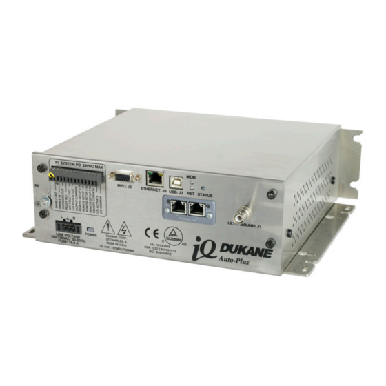
4. Connect the included ground wire from the grounding stud, in Figure 3-4, to earth ground. See CAUTION note on Page 21 . P1 System I/O Connector U/S Connector Grounding Stud Power Inlet Figure 3-2 Generator Front View Page 17 Dukane Manual Part No. 403-591-01... -
Page 24: P1 System I/O Connector Pinout
This output will be an open circuit if an output overload MPC module. condition is not tripped. This output will remain latched ON until the U/S Activate input is switched OFF and then ON again. Page 18 Dukane Manual Part No. 403-591-01... - Page 25 Pin 11 represents Setup Bit 3. This is the second most significant bit used to select different probe channels when a MPC Interface is used. This MPC control bit is used on MPC systems with nine or more channels. Page 19 Dukane Manual Part No. 403-591-01...
-
Page 26: Multi-Probe Control (Mpc)
MPC INTERFACE - Attach one end of the MPC Inter- number specifies cable length. This will face cable (Dukane # 200-1408-XX) to the MPC con- vary depending on your MPC installation. nector on the iQ generator panel in Figure 4-2. Connect the other end of the cable to the MPC INTERFACE connector on the right rear of the MPC module. - Page 27 (black carbon deposits) on On Off either the ultrasound output connector or the On On ultrasonic cable connectors. Off Off Off On On Off On On Table 3-III System I/O Remote Setup Inputs Page 21 Dukane Manual Part No. 403-591-01...
-
Page 28: Mpc Module Installation Guide
[57.2 mm] 10.88 1.75 10.50 2.25 MPC0808 [277 mm] [45 mm] [266.7 mm] [57.2 mm] 18.25 1.75 18.00 2.25 MPC1616 [464 mm] [45 mm] [457.2 mm] [57.2 mm] Figure 3-4 MPC Module Cutout Guide Page 22 Dukane Manual Part No. 403-591-01... -
Page 29: Connecting Cables
(or to the equipment enclosure into which your system is installed). 2. U/S (ultrasonic) cable (Dukane P/N 200-479-XXM - Order the correct cable length for your installation.) - Connect one end of the cable to the left rear U/S connector of the MPC module - B in Figure 3-5. -
Page 30: Mpc Module Status Leds
- trying to select channel 10 for an 8 channel system, for instance. If this lights up RED, a hardware fault has been sensed, and the unit should be returned to Dukane for NOTE servicing. Refer to Section 4, System Operation, for more information. -
Page 31: Section 4 - System Operation
LED Indication . . . . . . . . . . . . . . . . . . . . . . . . . . . . . . . . . . . . . . 31 Page 25 Dukane Manual Part No. 403-591-01... - Page 32 Series, Auto-Plus User’s Manual This page intentionally left blank Page 26 Dukane Manual Part No. 403-591-01...
-
Page 33: Introduction
This unit is automation ready and may be used as a stand-alone generator, or with its integrated Multi-Point Controller (MPC) Interface. The MPC interface, when connected to the Dukane MPC module, allows one generator to control up to 16 probes. The generator’s USB, EtherNet and ANYBUS ports extend communication and control functions depending on the specifications of a particular generator model. -
Page 34: Iq Auto-Plus System Operational Test
3. After completing Step 2, test ultrasound output by activating system I/O connector Pin 13. These status outputs will activate when there is a fault: Normal Condition: The system is operating properly when power is delivered to the attached stack. Continued Page 28 Dukane Manual Part No. 403-591-01... -
Page 35: Iq Auto-Plus System With Mpc Module Operational Test
If a circuit failure is discovered, return mation on wiring system controls, if needed. the MPC Module to Dukane for service. After completing Step 1, activate line power to the 3. After completing Step 2, test ultrasound output by standard iQ Auto-Plus system. - Page 36 • Overtemperature (Automatically resets on cool-down) • Power Not OK (AC line voltage under minimum voltage) • Frequency Overload (Automatically resets on next cycle) • Over Voltage Overload (Automatically resets on next cycle) Page 30 Dukane Manual Part No. 403-591-01...
-
Page 37: Led Indication
- POWER (1) - ETHERNET (2) - MOD (1) - NET (1) - STATUS (1) Figure 4-2 shows LED location, and Table 4-I shows their indications. ETHERNET STATUS POWER Figure 4-2 LED Locations Page 31 Dukane Manual Part No. 403-591-01... - Page 38 Reduce Power Mode (600W) Red to Yellow - Blinking Hardware/Configuration Fault Yellow - Blinking Power Not OK / Under AC Line Voltage Purple - Blinking Cycle Start Reject Table 4-I LED Colors and Indication Page 32 Dukane Manual Part No. 403-591-01...
-
Page 39: Section 5 - Options
ANYBUS Option . . . . . . . . . . . . . . . . . . . . . . . . . . . . . . . . . . 36 Dukane Manual Part No. 403-591-01... - Page 40 Series, Auto-Plus User’s Manual This page intentionally left blank Dukane Manual Part No. 403-591-01 Page 34...
-
Page 41: Heat Sink
Operate the iQ Auto-Plus gen- For applications that require higher duty cycles, an optional erator in the vertical position as cooling package is available. The Dukane Part Number for shown in Figure 5-1. This allows the package is 438-1020. for optimal air circulation enabling the heat sink to be most effective. -
Page 42: Distance Option
This option allows up to four analog 0-10VDC encoders to be monitored. A maximum of one customer supplied encoder per ultrasound channel. If more than one channel is needed a Dukane MPC module is required. With this option weld by position and distance functionality is available. -
Page 43: Section 6 - Automation Interface
. . . . . . . . . . . . . . . . . . . . . . . . . . . . . . . . . . 45 ™ Dukane Manual Part No. 403-591-01 Page 37... - Page 44 Series, Auto-Plus User’s Manual This page intentionally left blank Dukane Manual Part No. 403-591-01 Page 38...
-
Page 45: Input/Output Connection Examples
Remote Common (pin 12)! OVdc Return "#$%&!'()&*+,!-*#+,!. /!01'!234! "#$%&!/%55,#&! 23678 &9$ :!;!./!01'!<#$%&!! PNP Type Input Circuit Input Voltage Range 24VDC +/-10% Input Current 10mA (typ) @ 24VDC input Figure 6-1 PLC Sourcing (PNP) Type Output Circuit Dukane Manual Part No. 403-591-01 Page 39... -
Page 46: Plc Sinking (Npn) Type Output Circuit
(pin 11) OVdc Return "#$%&!'()&*+,!-*#+,!. /!01'!234! "#$%&!/%55,#&! 23678 &9$ :!;!./!01'!<#$%&!! NPN Type Input Circuit Input Voltage Range 24VDC +/-10% Input Current 10mA (typ) @ 24VDC input Figure 6-2 PLC Sinking (NPN) Type Output Circuit Page 40 Dukane Manual Part No. 403-591-01... -
Page 47: Plc Sourcing (Pnp) Type Input Circuit
U/S Status (pin 6) Output Common (pin 7) OVdc Return Input Voltage Range 24VDC +/-10% Input Current 10mA (typ) @ 24VDC input Output Driver PHOTOMOS RELAY Figure 6-3 PLC Sourcing (PNP) Type Input Circuit Dukane Manual Part No. 403-591-01 Page 41... -
Page 48: Plc Sinking (Npn) Type Input Circuit
24VDC +/-10% "#$%&!'()&*+,!-*#+,!. /!01'!234! Input Current 10mA (typ) @ 24VDC input "#$%&!/%55,#&! 23678 &9$ :!;!./!01'!<#$%&!! Output Driver PHOTOMOS RELAY =%&$%&!.5<>,5! ?@=A=B=C!-DE7F! PNP Type Output Circuit Figure 6-4 PLC Sinking (NPN) Type Input Circuit Page 42 Dukane Manual Part No. 403-591-01... -
Page 49: Dedicated E-Stop Switch Wiring Diagram
Automation System Safety Circuit Wiring Diagram System I/O Connector iQ Auto (Pin 1) Relay contact block Enable Out Master (Pin 2) control Enable In relay User automation control hardware Figure 6-5 E-STOP Wiring and Automation System Safety Circuit Dukane Manual Part No. 403-591-01 Page 43... -
Page 50: Ql In Q
HMI to program or monitor weld settings. 3. Weld cycle data from previous weld which includes: All Dukane iQ Auto Plus generators include iQLinQ ™ • Cycle Count EtherNet/IP and Modbus TCP/IP communication protocol •... -
Page 51: Iq Commander
Windows PC 1. Update the iQ Auto Plus generator firmware. based software, connected via a standard USB cable (Dukane part number 200-1906), can be used to configure 2. Test the ultrasonic stack. and monitor the iQ Auto-Plus generators. This tool allows 3. - Page 52 Series, Auto-Plus User’s Manual This page intentionally left blank Page 46 Dukane Manual Part No. 403-591-01...
-
Page 53: Section 7 - Contacting Dukane
Section 7 – Contacting Dukane SECTION 7 Contacting Dukane Dukane Manual Part No. 403-591-01 Page 47... - Page 54 Series, Auto-Plus User’s Manual This page intentionally left blank Page 48 Dukane Manual Part No. 403-591-01...
- Page 55 Section 7 – Contacting Dukane Contacting Dukane Identify Equipment When contacting Dukane about a service–related problem, be prepared to give the following information: • Model number, line voltage and serial number • Fault/error indicators from the Status LED and/or iQ Commander .
- Page 56 Series, Auto-Plus User’s Manual This page intentionally left blank Page 50 Dukane Manual Part No. 403-591-01...
-
Page 57: Section 8 - Specifications
Regulatory Agency Compliance . . . . . . . . . . . . . . . . . . . . . 58 Dukane Manual Part No. 403-591-01... - Page 58 Series, Auto-Plus User’s Manual This page intentionally left blank Page 52 Dukane Manual Part No. 403-591-01...
-
Page 59: Generator Outline Drawing
Section 8 – Specifications Figure 8-1 Generator Outline Drawing Dukane Manual Part No. 403-591-01 Page 53... -
Page 60: Weight, Operating Environment
Nonoperating storage guidelines: Temperature: -4°F to 158°F (-20°C to +70°C) Air Particulates: Keep the equipment dry. Minimize exposure to moisture, dust, dirt, smoke and mold. Humidity: 5% to 95% non–condensing @ 0°C to +30°C Page 54 Dukane Manual Part No. 403-591-01... -
Page 61: Ac Power Requirements
200-240V 50/60 Hz @ 15 Amps Max 40kHz 40AT060-UX-XX 100-240V 50/60 Hz @ 15 Amps Max 50kHz 50AT060-UX-XX 100-240V 50/60 Hz @ 15 Amps Max 70kHz 70AT012-UX-XX 100-240V 50/60 Hz @ 15 Amps Max Table 8-I AC Power Requirements Dukane Manual Part No. 403-591-01 Page 55... -
Page 62: Interpreting The Model Number
Series, Auto-Plus User’s Manual Interpreting the Model Number Figure 8-2 Interpreting the Model Number Page 56 Dukane Manual Part No. 403-591-01... -
Page 63: Iq Auto To Iq Auto Plus Inputs /Outputs Comparison
MPC Ready Out Ready Out MPC Ready Output is incorporated into the System Ready signal. Output Common Combined into P1 System I/O Connector. Table 8-II iQ Auto to iQ Auto Plus Inputs/Outputs Comparison Page 57 Dukane Manual Part No. 403-591-01... -
Page 64: Regulatory Agency Compliance
IP Rating The iQ generator has an IP (International Protection) rating from the IEC (International Electrotechnical Commission). The rating is IP2X, in compliance with finger-safe industry standards. Page 58 Dukane Manual Part No. 403-591-01... -
Page 65: Section 9 - Appendices
Appendix B, List of Tables . . . . . . . . . . . . . . . . . . . 61 Dukane Manual Part No. 403-591-01... -
Page 66: Appendix A List Of Figures
PLC Sinking (NPN) Type Output Circuit ................40 PLC Sourcing (PNP) Type Input Circuit.................41 PLC Sinking (NPN) Type Input Circuit ................42 E-STOP Wiring and Automation System Safety Circuit ..........43 Generator Outline Drawing ....................53 Interpreting the Model Number ..................56 Page 60 Dukane Manual Part No. 403-591-01... -
Page 67: Appendix B, List Of Tables
SMPC I/O Connector Signals ..................21 3-III System I/O Remote Setup Inputs ...................21 3-IV Probe Cables ........................23 LED Colors and Indication ....................32 AC Power Requirements ....................55 8-II iQ Auto to iQ Auto Plus Inputs/Outputs Comparison ............57 Dukane Manual Part No. 403-591-01 Page 61... -
Page 68: Index
Drawings and Tables 3 Multi-Probe Control (MPC) 20 Notes, Cautions and Warnings 3 Read This Manual First 3 Generator Overview Notes, Cautions and Warnings 3 Key Features 4 Generator Overview 4 Thermal Considerations 5 Page 62 Dukane Manual Part No. 403-591-01... - Page 69 Interpreting the Model Number 56 iQ Auto to iQ Auto Plus - Inputs/Outputs Comparison 57 Operating Environment 54 Weight 54 System Operation Introduction 27 iQ Auto-Plus System Operational Test 28 LED Indication 31 Thermal Considerations 5 Dukane Manual Part No. 403-591-01 Page 63...
- Page 70 Dukane can assure you that based on partnership for continuous improve- we have in place a well–defined and systematic ment. This concept is key in that Dukane no approach to quality design, manufacturing, longer focuses on inspection, but on individual delivery and service.
- Page 71 Please refer to our website at: www .dukane .com/contact-us/ to locate your local representative. iQ Series , Ultrasonic Generator/Power Supply www.dukane.com Auto-Plus User's Manual Part No. 403-591-01 Dukane • 2900 Dukane Drive • St. Charles, Illinois 60174 USA • TEL (630) 797- 4900...
Need help?
Do you have a question about the iQ Auto-Plus 20AT060-U Series and is the answer not in the manual?
Questions and answers