Table of Contents
Advertisement
Quick Links
Advertisement
Table of Contents

Subscribe to Our Youtube Channel
Related Manuals for Dukane AiM iQ Series


Summary of Contents for Dukane AiM iQ Series
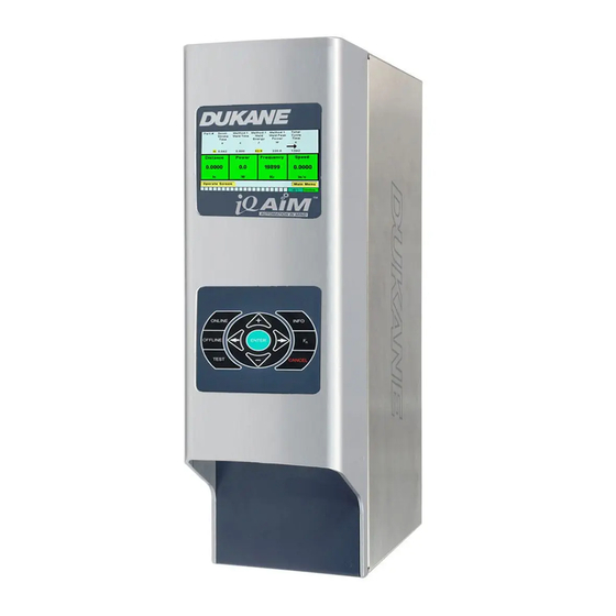
- Page 1 ULTRASONIC POWER SUPPLY ™ Color Front Panel AUTOMATED HAND PROBE PRESS Dukane Part No. 403-610-02 Dukane IAS • 2900 Dukane Drive • St. Charles, Illinois 60174 USA • TEL (630) 797- 4900 Dukane products are manufactured in www.dukane.com ISO registered facilities...
- Page 2 The information contained in this manual is distributed on an “As is” basis, without warranty. While every precaution has been taken in the preparation of this manual, Dukane shall not have any liability to any person or entity with respect to any liability, loss, or damage caused or alleged to be caused directly or indirectly by the instructions contained in this manual, or by the hardware products described herein.
- Page 3 Added additional outline drawings on Pgs.53-55. Revised AC Power Requirements table on Pg. 54. Revised Model Number chart on Pg. 55. Revised Regulatory Agency Compliance on Pg. 56. - 02 Added SCCR to Pg. 6. April 6, 2021 Page iii Dukane Manual Part No. 403-610-02...
- Page 4 Series AiM Automation in Mind, ™ Ultrasonic Power Supply User’s Manual This page intentionally left blank Page iv Dukane Manual Part No. 403-610-02...
-
Page 5: Table Of Contents
Section 5 - Contacting Dukane . . . . . . . . . . . . . . . . . . - Page 6 Series AiM Automation in Mind, ™ Ultrasonic Power Supply User’s Manual This page intentionally left blank Page vi Dukane Manual Part No. 403-610-02...
-
Page 7: Section 1 - Introduction, Health And Safety
Short-Circuit Current Rating ....... . .6 Page 1 Dukane Manual Part No. 403-610-02... - Page 8 Series AiM Automation in Mind, ™ Ultrasonic Power Supply User’s Manual This page intentionally left blank Page 2 Dukane Manual Part No. 403-610-02...
-
Page 9: General User Information
(e.g. I, II, III). As an example, Figure 3- 2 would be the second illustration in Section 3 while Table 3- I I would be the second table in Section 3. Condition Hearing Electrical or Practice Protection Hazard Page 3 Dukane Manual Part No. 403-610-02... -
Page 10: General Considerations
No Unauthorized Modifications - Do not modify your and fixture. system in any way unless authorized to do so by Dukane. Unauthorized modifications could cause equipment dam- age and/or injury to the operator. In addition, unauthorized modifications will void equipment warranty. -
Page 11: Plastics Health Notice
Inquiries should be made to the U.S. Department of Labor concerning OSHA regulations for a particular plastic prior to processing with Dukane ultrasonic equipment Electrical Safety CAUTION The iQ Series generator provides the operating power When making cable connec- and power returns. -
Page 12: Domestic Power Grounding
The cord should have an ad- equate power rating to do the job safely. It must be plugged into a grounded receptacle. Do not use a two-wire exten- sion cord with this product. Page 6 Dukane Manual Part No. 403-610-02... -
Page 13: Section 2 - Installation
Avoid Excessive Bending ........13 Page 7 Dukane Manual Part No. 403-610-02... - Page 14 Series AiM Automation in Mind, ™ Ultrasonic Power Supply User’s Manual This page intentionally left blank Page 8 Dukane Manual Part No. 403-610-02...
-
Page 15: Connecting Cables
2600W use permanently at- tached power cords. NEMA L6-30P Dukane part number 570-296 Figure 2-1 North American Plug IEC 60309 (Sleeve 332P6) Dukane part number 570-301 Figure 2-2 International Plug Page 9 Dukane Manual Part No. 403-610-02... -
Page 16: Dc Power
380/480 VAC 3 Phase Line Wiring Information is found on Page 11. Figure 2 - 5 +24 VDC Control Power Cord Figure 2 - 3 AC Power Cord Mounting Plate Figure 2 - 4 AC Wires Terminal Connector Page 10 Dukane Manual Part No. 403-610-02... -
Page 17: Wiring Information For 380/480 Vac 3 Phase Lines
3 Phase 380/480 Volt connections should be wired as shown below. Figure 2 - 7 Wiring a 3 Phase 380/480 Volt Circuit (Delta) For more details, refer to Application Note AN524 found on the Dukane website at: https://documents.dukane.com/AppNote/AN524.pdf Page 11... -
Page 18: Automation Controlled Probe System
5. Connect the AC power cord to the generator IEC power inlet connector, and plug the other end into an approved AC outlet: in Figure 2-8. SYSTEM I/O AC POWER ENTRY ULTRASOUND Figure 2-8 Generator - Bottom View (Vertical Panel Mount Chassis) Page 12 Dukane Manual Part No. 403-610-02... -
Page 19: Proper Handling Of Cable Slack
Avoid excessive tension and bends on cables. Cables should be routed so that there are no abrupt bends in the cables, especially near their connectors. Figure 2-9 Cable Slack Take-up - Correct Figure 2-10 Cable Slack Take-up - Incorrect Page 13 Dukane Manual Part No. 403-610-02... - Page 20 Series AiM Automation in Mind, ™ Ultrasonic Power Supply User’s Manual This page intentionally left blank Page 14 Dukane Manual Part No. 403-610-02...
-
Page 21: Section 3 - Standard Connections
. . . . . . . . . . . . . . . . . . . . . . . . . . . . . 25 Page 15 Dukane Manual Part No. 403-610-02... - Page 22 Series AiM Automation in Mind, ™ Ultrasonic Power Supply User’s Manual This page intentionally left blank Page 16 Dukane Manual Part No. 403-610-02...
-
Page 23: Bottom Panel Layout Overview
(RFI) that is common in an industrial envi- ronment. The chassis ground stud is in Figure 3-1. Proper system grounding is discussed in Section 2. Page 17 Dukane Manual Part No. 403-610-02... -
Page 24: System Inputs/Outputs Connector
Do not repeatedly try to reset the circuit breaker. If it trips, without adding a separate power supply, if desired. this will only cause more damage to the generator. Refer to Application Note AN525 found on the Dukane website at: SYSTEM INPUTS/OUTPUTS CONNECTOR https://documents.dukane.com/AppNote/AN525.pdf... -
Page 25: System Inputs/Outputs Signal Descriptions
Depending on the welding process controller setup, this input signal could be activated momentarily to start a welding cycle. Continued Page 19 Dukane Manual Part No. 403-610-02... - Page 26 DISTANCE or POSITION. When using either of these Pin 20 is a programmable output that defaults to a digital weld methods, it is also recommended using Dukane’s output that activates whenever any fault condition is Trigger by Power feature. Dukane recommends using the detected that terminates/inhibits ultrasound output and MPS series analog encoder made by SICK or equivalent.
- Page 27 This includes system faults or E-STOP active, but not a process fault like Overload. Figure 3-3 J5 Pin 14 Encoder Wiring Information Page 21 Dukane Manual Part No. 403-610-02...
- Page 28 The exception is the ULTRASOUND ACTIVATION / CYCLE START INPUT which cannot be programmed to another function. 2. Connector Input pins 5 through 10 can be re-assigned from their default setting to be System Latch Reset. Page 22 Dukane Manual Part No. 403-610-02...
-
Page 29: Ultrasound Output Connector
Do not use the generator if there is any evidence arcing (black carbon deposits) on either the ultrasound output connector or the ultrasonic cable connectors. Page 23 Dukane Manual Part No. 403-610-02... -
Page 30: Ethernet/Ip Port Connector
Connect a Windows PC to this port using the included the iQ generator to connect to an EtherNet/IP or Modbus USB cable in order to use Dukane’s PC interface tool, iQ TCP/IP network. This port is used for Dukane’s iQLinQ Commander . -
Page 31: Iq Commander Tm
This Windows based software, connected via a standard 1. Update the iQ AiM generator firmware. Type A to Type B (Dukane part number 200-1906) USB 2. Test the ultrasonic stack. cable, can be used to configure and monitor the iQ AiM 3. - Page 32 Series AiM Automation in Mind, ™ Ultrasonic Power Supply User’s Manual This page intentionally left blank Page 26 Dukane Manual Part No. 403-610-02...
-
Page 33: Section 4 - Standard System Status And Controls
Stopping the Ultrasound Output ......43 Dukane Manual Part No. 403-610-02 Page 27... - Page 34 Series AiM Automation in Mind, ™ Ultrasonic Power Supply User’s Manual This page intentionally left blank Page 28 Dukane Manual Part No. 403-610-02...
-
Page 35: Front Panel Controls
— Taking a look at setup identification. Online/Offline/E-STOP Status System Power Output Level Navigation Keys (4) INFO Key System Operating Mode Keys (3) CANCEL Key ENTER Key Figure 4 - 1 Front Panel Controls Dukane Manual Part No. 403-610-02 Page 29... -
Page 36: System Operating Mode Keys
Figure 4-3 Display Detail, Power Output Level signal. The word, Offline appears in the display's upper right corner and the display background is yellow. Page 30 Dukane Manual Part No. 403-610-02... -
Page 37: Navigation Keys
INFO Key Press the INFO key, and the menu shown to the right in Figure 4-5 Info Menu Display Figure 4-5 appears. Dukane Manual Part No. 403-610-02 Page 31... -
Page 38: Screen Basics
Figure 4-7. For this screen, (up or down) navigation keys are used to move in the direction of the on-screen arrow. Display arrow points in direction of more text Figure 4-7 Arrows Indicate Direction of More Text Page 32 Dukane Manual Part No. 403-610-02... -
Page 39: System Power Output Level
Example: With a 1200W generator, at 50% amplitude, if the whole graph is lit, that represents 600W. CAUTION If an alarm indicates there is an overload alarm, verify that the ultrasonic stack is not damaged. Dukane Manual Part No. 403-610-02 Page 33... -
Page 40: Setup Identification
MPC Probe 8 is selected by the generator. This is useful analog input and if “OTF” is displayed a PLC controls for checking the generator to MPC wiring if the cable amplitude. that connects them together has been modified. Continued Page 34 Dukane Manual Part No. 403-610-02... - Page 41 This field is editable when DHCP is disabled. 5. NETWORK LINK: Indicates the state of the Ethernet link. Down is not plugged in, 10Mbps (Half), 10Mbps (Full), 100Mbps (Half), 100Mbps (Half/Full Duplex). Continued Dukane Manual Part No. 403-610-02 Page 35...
- Page 42 Restore Factory Defaults Restore Factory Defaults Deletes all setups and restores all parameters to factory defaults. An intermediate display allows for confirmation. When confirmed, factory defaults are restored. Figure 4-11 Miscellaneous Sub-menu Items Page 36 Dukane Manual Part No. 403-610-02...
-
Page 43: Alarms
Weld Distance Set to Zero U405 Weld Position Set to Zero U406 Max Trigger Time Set to Zero U413 Max Trigger Time Exceeded (The trigger did not occur within the specified time limit.) Table 4-I Alarm Messages Dukane Manual Part No. 403-610-02 Page 37... -
Page 44: Multi-Point Control (Mpc) Interface
This will vary depending on your MPC installation. face cable (Dukane # 200-1408-XX) to the MPC con- nector on the iQ generator panel in Figure 4-2. Connect the other end of the cable to the MPC INTERFACE connector on the right rear of the MPC module. - Page 45 (black carbon deposits) on On Off either the ultrasound output connector or the On On ultrasonic cable connectors. Off Off Off On On Off On On Table 4 - III MPC Setup Bit Inputs Dukane Manual Part No. 403-610-02 Page 39...
-
Page 46: Iqlinq Tm
Factory View Studio ME), Siemens (TIA Portal), and • Weld End Position B&R (Automation Studio) PLC projects. For information on how to control and/or monitor specific pa- Contact your local Dukane representative for more rameters, iQ Generator iQLinQ Communication and Control ™... -
Page 47: System Verification Tests
Figure 4 - 1 7 Testing the Generator The ultrasound status output activates only when ul- trasound is active. The power monitor output signal indicates the ultrasonic power level. Dukane Manual Part No. 403-610-02 Page 41... -
Page 48: System Test
ER OUTPUT LEVEL bar graph turns off (no red in the bar graph area). This test cannot be performed with the generator OFFLINE. Figure 4 - 1 8 Test Key Figure 4 - 1 9 System Test Page 42 Dukane Manual Part No. 403-610-02... -
Page 49: Probe Operation
Press the emergency (E-STOP) switch, and the ultrasound signal will deactivate. - This supplied switch is wired to J5 pins 3 and 4 (see System Inputs/Outputs Signal Descriptions pg. 19) and opens the connection between those pins when pressed. Dukane Manual Part No. 403-610-02 Page 43... - Page 50 Series AiM Automation in Mind, ™ Ultrasonic Power Supply User’s Manual This page intentionally left blank Page 44 Dukane Manual Part No. 403-610-02...
-
Page 51: Section 5 - Contacting Dukane
Section 5 - Contacting Dukane SECTION 5 Contacting Dukane Dukane Manual Part No. 403-610-02 Page 45... - Page 52 Series AiM Automation in Mind, ™ Ultrasonic Power Supply User’s Manual This page intentionally left blank Page 46 Dukane Manual Part No. 403-610-02...
- Page 53 Section 5 - Contacting Dukane Contacting Dukane Identify Equipment When contacting Dukane about a service–related problem, be prepared to give the following information: • Model number, line voltage and serial number • Alarm/Fault indicators from the display • Software version (Press .
- Page 54 Series AiM Automation in Mind, ™ Ultrasonic Power Supply User’s Manual This page intentionally left blank Page 48 Dukane Manual Part No. 403-610-02...
-
Page 55: Section 6 - Specifications
Regulatory Agency Compliance . . . . . . . . . . . . . . . 59 Dukane Manual Part No. 403-610-02 Page 49... - Page 56 Series AiM Automation in Mind, ™ Ultrasonic Power Supply User’s Manual This page intentionally left blank Page 50 Dukane Manual Part No. 403-610-02...
-
Page 57: Generator Drawings
Section 6 - Specifications Figure 6 - 1 Horizontal 2600 watts and below Generator Drawing Dukane Manual Part No. 403-610-02 Page 51... - Page 58 Series AiM Automation in Mind, ™ Ultrasonic Power Supply User’s Manual Figure 6 - 2 Vertical 2600 watts and below Generator Drawing Page 52 Dukane Manual Part No. 403-610-02...
- Page 59 Section 6 - Specifications Figure 6-3 Horizontal/Vertical 3600 watt Single Phase Generator (Drawing 400-2561) Dukane Manual Part No. 403-610-02 Page 53...
- Page 60 Series AiM Automation in Mind, ™ Ultrasonic Power Supply User’s Manual Figure 6-4 Vertical 3600 and 5000 watt Single Phase Generator (Drawing 400-2514) Page 54 Dukane Manual Part No. 403-610-02...
- Page 61 Section 6 - Specifications Figure 6-5 Horizontal/Vertical 5000 watt Single Phase Generator (Drawing 400-2558) Dukane Manual Part No. 403-610-02 Page 55...
-
Page 62: Operating Environment
Storage guidelines (generator is not operating): Temperature: -4°F to 158°F (-20°C to +70°C) Air Particulates: Keep the equipment dry Minimize exposure to moisture, dust, dirt, smoke and mold Humidity: 5% to 95% Non–condensing @ 0°C to +30°C Page 56 Dukane Manual Part No. 403-610-02... -
Page 63: Ac Power Requirements
Section 6 - Specifications Dukane Manual Part No. 403-610-02 Page 57... -
Page 64: Interpreting The Model Number
Series AiM Automation in Mind, ™ Ultrasonic Power Supply User’s Manual Figure 6- 3 Interpreting the Model Number Page 58 Dukane Manual Part No. 403-610-02... -
Page 65: Regulatory Agency Compliance
IP Rating The iQ generator has an IP (International Protection) rating from the IEC (International Electrotechnical Commission). The rating is IP2X, in compliance with finger-safe industry standards. Dukane Manual Part No. 403-610-02 Page 59... - Page 66 By passing its audit, Dukane can as- based on partnership for continuous improve- sure you that we have in place a well–defined ment. This concept is key in that Dukane no and systematic approach to quality design, longer focuses on inspection, but on indi- manufacturing, delivery and service.
- Page 67 .dukane .com/contact-us/ to locate your local representative. www.dukane.com iQ Series, AiM Color Front Panel ™ Part No. 403-610-01 Printed in the United States of America Dukane IAS • 2900 Dukane Drive • St. Charles, Illinois 60174 USA • TEL (630) 797-4900...
Need help?
Do you have a question about the AiM iQ Series and is the answer not in the manual?
Questions and answers