Sharp ER-A770 Installation Manual
Pos terminal for "u"&"a" version
Hide thumbs
Also See for ER-A770:
- Instruction manual (241 pages) ,
- Manual (94 pages) ,
- Dealer knowledge book (29 pages)
Table of Contents
Advertisement
Quick Links
1. Removing the rear cover ......................................................................................... 2
2. Replacing the rear cover ......................................................................................... 2
3. Removing the top cabinet ....................................................................................... 2
4. Replacing the top cabinet........................................................................................ 3
5. Removing the Noise filter PWB, Transformer and AC cord .................................... 3
6. Replacing the Noise filter PWB and Transformer.................................................... 3
7. Removing and replacing the keyboard unit ............................................................. 3
8. Removing and replacing the LCD unit..................................................................... 4
9. Expansion RAM Board : UP-P02MB2..................................................................... 4
10. RS232 I/F: ER-A7RS .............................................................................................. 4
11. MCR unit: UP-E12MR ............................................................................................. 5
12. Drawer box unit: ER-03DW/04DW.......................................................................... 5
13. Customer display: UP-I16DP .................................................................................. 5
14. Remote display: UP-P16DP .................................................................................... 6
15. How to extend display pole: UP-P16DP.................................................................. 7
16. SRN I/F: Standard................................................................................................... 8
17. RS232 I/F: Standard ............................................................................................... 8
Parts marked with "
" are important for maintaining the safety of the set. Be sure to replace these parts with specified
ones for maintaining the safety and performance of the set.
MODEL
CONTENTS
SHARP CORPORATION
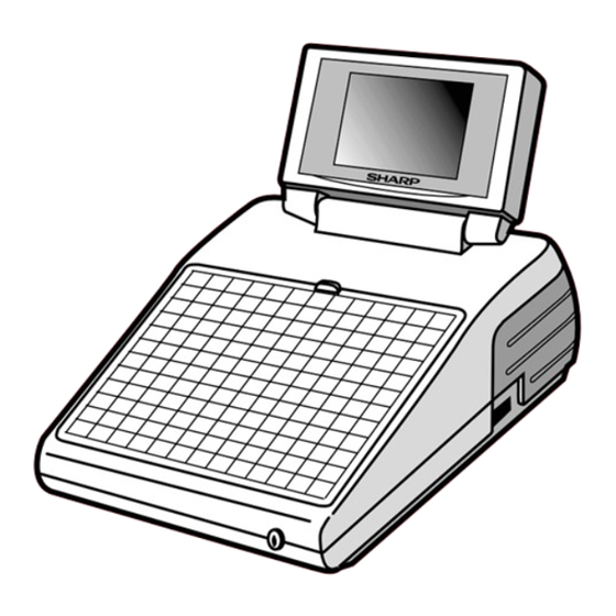
POS TERMINAL
ER-A770
(For "U"&"A" version)
This document has been published to be used
for after sales service only.
The contents are subject to change without notice.
Advertisement
Table of Contents

Related Manuals for Sharp ER-A770


Summary of Contents for Sharp ER-A770
-
Page 1: Table Of Contents
POS TERMINAL ER-A770 MODEL (For "U"&"A" version) CONTENTS 1. Removing the rear cover ..................2 2. Replacing the rear cover ..................2 3. Removing the top cabinet ..................2 4. Replacing the top cabinet..................3 5. Removing the Noise filter PWB, Transformer and AC cord ........3 6. - Page 2 Symbol/PartsCod) - - - - - - - - - - - - - - - - - - - - - - - - - - - - - - - - - - - - - - - - - - - - - - - - - - - - - - - Example of wiring for all optional devices connected to the system unit.
-
Page 3: Removing The Rear Cover
• Cable between the main PWB and the LCD: (CN10) Precautions • • Cable between the main PWB and the CKDC PWB: Before installation, be sure to disconnect the AC power. • (CN8) Use gloves to protect your hands from being cut by the angle and the chassis. -
Page 4: Replacing The Top Cabinet
4. Replacing the top cabinet 6. Replacing the Noise filter PWB and Transformer Install the top cabinet in the reverse order of removing. Before install- ing, make sure that each connector is connected securely. Install the power supply unit in the reverse order of removing. Before installing, make sure that each connector is connected securely. -
Page 5: Removing And Replacing The Lcd Unit
8. Removing and replacing the LCD 9. Expansion RAM Board : unit UP-P02MB2 1) Remove the four fixing screws of the display unit from the top Make sure to save data before installing this option. Also make sure the capacitor (C32) is positioned in the direc- cabinet tion opposite the connector ;... -
Page 6: Mcr Unit: Up-E12Mr
12. Drawer box unit: ER-03DW/04DW 1) Connect the drawer cable to the drawer connector ER-A7RS 2) Fix the earth wire from drawer box unit with the screw ER-A7RS RS232 cable RS232 cable Fig. 8 11. MCR unit: UP-E12MR 1) Fix the MCR angle to the lower cabinet with two screws 2) Remove the three screws 1 t u r n... -
Page 7: Remote Display: Up-P16Dp
5) Make sure the display cable passes under it. Fig. 14 6) Connect to the display cable to the display connector. Note : The ER-A770 can only support 1 type customer display at a time either the UP-I16DP or UP-P16DP. -
Page 8: How To Extend Display Pole: Up-P16Dp
5) Turn the ratchet connected to the pole cabinet to the removing 15. How to extend display pole: position and pull it out from the display unit as shown in Fig. A. UP-P16DP 6) Remove the two screws 7) Remove the pole cabinet from the Ratchet The pole can be extended by installing the attached pole to the standard pole. -
Page 9: Srn I/F: Standard
10) Fastening onthe table: 16. SRN I/F: Standard Secure the Base cabinet using the screw. NAME Q’ty 1) Connect to the SRN cable to the SRN connector Securing the UP-P16DP to the Screw (M4 × 16) 2) Install the Ferrite core to the SRN cable wooden table 3) Install the Nylon band... - Page 10 © COPYRIGHT 2000 BY SHARP CORPORATION All rights reserved. Printed in Japan. No part of this publication may be reproduced, stored in a retrieval system, or transmitted. In any form or by any means, electronic, mechanical, photocopying, recording, or otherwise, without prior written permission of the publisher.
Need help?
Do you have a question about the ER-A770 and is the answer not in the manual?
Questions and answers