Advertisement
Advertisement
Table of Contents

Subscribe to Our Youtube Channel
Related Manuals for LAE electronic COPS 80


Summary of Contents for LAE electronic COPS 80
- Page 1 COPS 80 Instructions for installation and use...
-
Page 2: Installation
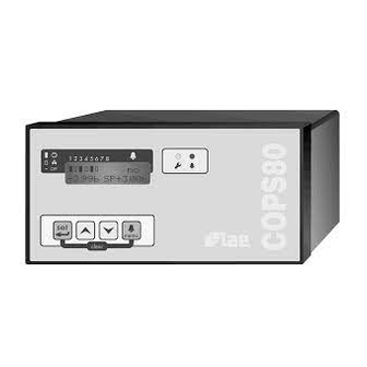
Before proceeding to the installation of the COPS 80, we recommend you to read this instruction booklet carefully and entirely. Only in this way you will obtain maximum performance and reliability. The COPS 80 controls the suction pressure on multi-compressor packs for variable demand cryogenic plants. - Page 3 LED [3] blinks when an internal or external alarm is detected. 3 PROGRAMMING The COPS 80 is a controller able to perform complex control functions to the best, it must therefore be able to recognize the plant connected to it without any doubt. To this purpose, before the first system start-up, it is mandatory to program the configuration parameters carefully in order to obtain a perfect adaptation of the COPS 80 control algorithms to the specific plant.
-
Page 4: Operation
50. full scale adjust, allows span recalibration. 4 OPERATION On every power-up, after self-check (4 sec approx.), the COPS 80 starts to control according to the latest programmed values. STAND-BY. With par.2=YES the control functions are suspended, the COPS proceeds to progressively switching off all the outputs with fixed 5 sec steps and on area [7] of the display "stand-by"... - Page 5 5. ANOMALIES AND ALARMS The COPS 80 features a sophisticated abnormal operation condition detection system. When an anomaly is detected, area [8] of the display shows its source (see 2.3) and, as long as the condition persists, the alarm relay contacts will change status and LED [3] blinks. The buzzer goes off simultaneously with the other signallings but it can be muted by pressing any of the keys.
-
Page 6: Auxiliary Functions
WARRANTY LAE electronic Srl warrant that their products are free of any defects in workmanship and materials for a period of 1 (one) year from date of production shown on the enclosure. LAE electronic Srl shall only repair or replace those products of which defects are due to LAE electronic Srl and recognised by their technicians. - Page 7 FIGURE 2 1-2 Power supply 230 Vac, 50/60 Hz 11-12 High Pressure switch 110-240 Vac, 50/60 Hz (3)-4 Pressure transmitter input 13-14 Low Pressure switch 110-240 Vac, 50/60 Hz 5 Transmitter supply +8...+16 Vdc, 25 mA 15-16 Refrigerant Level 110-240 Vac, 50/60 Hz 6-7 RS 485 serial communication port 17-18 Alternative Set 110-240 Vac, 50/60 Hz 8-9-10 Alarm relay 240 Vac, 5 A...
- Page 8 TABLE A Par.N Identification Minimum and Maximum Limits Factory Setting Current Value pass code 0 ... 255 ____ stand-by YES / NO ____ (language) Italiano... English Español LCD contrast 00 ... 100 LEVEL #1, accessible with pass code 24 main SET min.range ...
- Page 9 out 3 run time 0 ... 50 hours out 4 run time 0 ... 50 hours out 5 run time 0 ... 50 hours out 6 run time 0 ... 50 hours out 7 run time 0 ... 50 hours out 8 run time 0 ...
Need help?
Do you have a question about the COPS 80 and is the answer not in the manual?
Questions and answers