Table of Contents
Advertisement
Quick Links
Advertisement
Table of Contents

Related Manuals for Schletter PvMax3

Summary of Contents for Schletter PvMax3
- Page 1 PvMax3 Mounting Instructions Schletter GmbH Gewerbegebiet an der B15 Alustrasse 1 83527 Kirchdorf / Haag in OB GERMANY Phone: +49 8072 9191 - 0 E-mail: info@schletter.eu Your contact: Technical advice for ground-mounted solar plants Phone: +49 8072 9191 - 203 E-mail: tb-freifl aeche@schletter.de...
- Page 2 PvMax3 Mounting Instructions © Schletter GmbH as of 10/2016...
-
Page 3: Table Of Contents
6.1. Module mounting in case of horizontal (landscape) or vertical (portrait) module bearing ........31 6.2. Module mounting and clamping in case of combined module bearing ................ 32 7. Disassembly and disposal ..............................33 8. Maintenance and care ................................34 9. Warranty and liability ................................34 © Schletter GmbH as of 10/2016... -
Page 4: General Information
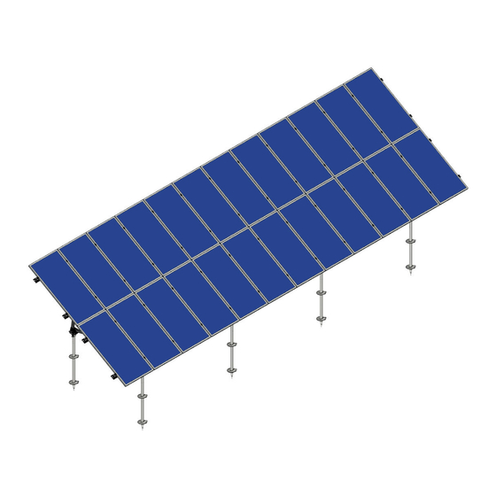
As the individual components have been optimized and structurally synchronized, a minimum system price is achieved. PvMax3 allows to use framed as well as unframed modules that can be mounted either in portrait or in landscape, or with the Schletter combined clamping system. It is also possible to mount additional accessories for the cable management or components for the internal potential equalization. -
Page 5: Safety Information
(water, electricity, gas) in the relevant area. For this purpose, the position of all supply lines (water, gas, electricity, etc.) must be marked using marking paint and unstable ground and areas that are landslide-prone must be sealed off with stable barriers or warning signs. © Schletter GmbH as of 10/2016... - Page 6 REFERENCES All documents relevant for the mounting that are not included in these Mounting Instructions, are marked with this symbol. We absolutely recommend to observe the following protective measures when mounting PvMax3: Remember to wear high- Always wear ear protection...
-
Page 7: Obligation Of The Plant Owner / Operating Company
• Personnel that still is to be trained may only mount the PvMax3 system under the supervision of an experienced person. We recommend the operator to insist on a confirmation in writing in each case. 1.7. Training of the Personnel... -
Page 8: Additional Documents Relevant For The Mounting
PvMax3 Mounting Instructions 1.8. Additional Documents Relevant for the Mounting In addition to these Mounting Instructions, the following documents are required for the mounting of PvMax3: • Reinforcement plan (optional) • Blueprint drawing / general layout drawing • Bill of materials / parts list •... -
Page 9: Provide Forklift Trucks And Hoisting Equipment
A general right to return purchased goods is not granted. Extract from the General Terms and Conditions of Sale and Supply of Schletter GmbH - download available at www.schletter.de/AGB_en 2.5. Storage of the components The components will also be delivered in cardboard boxes on pallets. -
Page 10: Technical Data
3.2. Rack tolerances PvMax3 is always confi gured specifi cally for the wind and snow loads at the respective installation site. In the interest of economic effi ciency, usually the maximum load-bearing capacity of the individual component is exploited. To achieve this, however, the racks must be mounted with the utmost precision. -
Page 11: Systems Overview
Girder to strut connector rear Detail A Detail B Detail C Fig. 3.3.-2. (detail A) Fig. 3.3.-3. (detail B) Fig. 3.3.-4. (detail C) © Schletter GmbH as of 10/2016... -
Page 12: Components
PvMax3 strut assembly V55-D55-H55 147007-002 PvMax3 strut assembly V75-D75-H75 147007-003 PvMax3 strut assembly V55-D75-H75 147007-004 PvMax3 strut assembly V55-D75-H55 / V55-D55-H75 3.4.2. Components of the strut assembly Fig. 3.4.1.-1 (147007-002) 000011-126 PvMax3 Strut 55x55 front custom cut 000011-127 PvMax3 Strut 55x55 diag. custom cut... -
Page 13: Girder Assemblies
Girder assembly FS2V-BF0 146121-000 Girder assembly FS2V-BF1 146122-000 Girder assembly FS2V-BF2 146123-000 Girder assembly FS2V-BF3 146130-000 Girder assembly FS3V-BF0 146131-000 Girder assembly FS3V-BF1 146132-000 Girder assembly FS3V-BF2 146133-000 Girder assembly FS3V-BF3 146140-000 Girder assembly FS4V-BF0 © Schletter GmbH as of 10/2016... -
Page 14: Girder Assemblies
Module-bearing rail S1.5 - custom cut 124307-001 Module-bearing rail S1.8 - custom cut 124304-001 Module-bearing rail S2 - custom cut 124305-001 Module-bearing rail S3 - custom cut 124306-001 Module-bearing rail S4 - custom cut © Schletter GmbH as of 10/2016... -
Page 15: Purlin Connector
Proklip2000-B cable clip round duct M10 129012-002 Proklip2000-P round cable clip for the S design Fig. 3.4.6.-3 (129065-008) 129065-008 Proklip-Multi8 129065-010 Proklip-Multi10 129042-001 Proklip-F 129012-008 Proklip-S rectangular cable clip for M8 channel Fig. 3.4.6.-4 (129012-001) 129012-001 Proklip-Q © Schletter GmbH as of 10/2016... -
Page 16: Module Clamping
The Standard clamps are not pre-assembled when they are delivered. These clamps are combined with a hexagon socket head screw, a KlickIn click component and a square nut. The screws listed below can be used for that purpose: © Schletter GmbH as of 10/2016... -
Page 17: Screws For Standard Module Clamps
Hexagon socket screw M8x20 serrated DIN912 A3 943308-125 36 - 40 Hexagon socket screw M8x25 serrated DIN912 A3 943308-130 41 - 45 Hexagon socket screw M8x30 serrated DIN912 A3 943308-135 46 - 51 Hexagon socket screw M8x35 serrated DIN912 A3 © Schletter GmbH as of 10/2016... -
Page 18: Mounting Information
PvMax3 Mounting Instructions 4. Mounting information The PvMax3 system is customized for the respective installation site. The following indications are already needed during the planning process: • Site boundaries • Rights of way / easements (the building site must be accessible for vehicles at any time) •... -
Page 19: Foundation
4.2.3. Preparation of the soil and positioning of the foundations Before setting up the PvMax3 system, the terrain must be prepared for the positioning of the concrete foundations. Please consider that individual sub-racks that are part of one rack are not parallel to the subsoil beneath them. Thus, the foundations have to aligned correctly. - Page 20 Fig. 4.2.3.-2 (aligning the concrete foundations on a gravel bed) NOTICE Also when using a cast-in-place foundation, make sure that the foundations are cast up to the same height. Cast-in-place Casting concrete mold Fig. 4.2.3.-3 (flush height cast-in-place foundation) © Schletter GmbH as of 10/2016...
-
Page 21: Tolerances Regarding Inclination And Distortion (Twist)
4.3. Tolerances regarding inclination and distortion (twist) Twist of the support on the con- Inclination of the concrete foundation (East-West) crete foundation + 2° + 2° Fig. 4.3.-1 (twisting of the support) Fig. 4.3.-2 (east-west tilt of the concrete foundation) © Schletter GmbH as of 10/2016... -
Page 22: Tools
PvMax3 Mounting Instructions 4.4. Tools In the following, the tools that are usually required for mounting the PvMax3 system are listed. Additional tools that are required for special cases (for example encasing the foundations in concrete) are not listed here. -
Page 23: Module Mounting
Washer 10.5 DIN7349 A2 Fig. 4.5.1.-4 (screw connection M10x30) Hexagon head screw M10x25 DIN933 33 Nm A2 GMC Square nut M10 DIN557 A4 KlickIn click component for nut M10 Fig. 4.5.1.-5 (screw connection M10x25) © Schletter GmbH as of 10/2016... -
Page 24: Fastening Of The Module Clamps
This was taken into consideration when the tightening torques were determined. When a bolted connection is checked, it must not loosen when 50% of the specifi ed tightening torque is applied. Fig. 4.5.2.-2 (Rapid module clamp) © Schletter GmbH as of 10/2016... -
Page 25: Assembly Steps
The selected fasteners (e.g. screw anchors/dowels) must be appropriate for the fastening forces that are specified in the structural analysis! For this purpose, a corresponding data sheet has to be added to the documents. The required fasteners are NOT included in the scope of delivery! © Schletter GmbH as of 10/2016... - Page 26 Fig. 5.1.-2 (inserting the fasteners) Position the strut assembly onto the fasteners and fasten using nuts. Fig. 5.1.-3 (positioning and fastening the strut assembly) Fig. 5.1.-4 (PvMax3 front base bracket) Fig. 5.1.-5 (PvMax3 rear base bracket) © Schletter GmbH as of 10/2016...
-
Page 27: Mounting The Girder Assembly
4 KlickIn click components • 4 square nuts Fig. 5.2.-1 (inserting the KlickIn click components and square nuts) Place the girder assembly onto the girder to strut connector. Fig. 5.2.-2 (placing the girder assembly) © Schletter GmbH as of 10/2016... -
Page 28: Mounting The Module-Bearing Rails
Please again check the distances after you have mounted the module-bearing rails! Distance between the module-bearing rails Check the 90° angle (at all junction points) Fig. 5.3.-1 (checking the module-bearing rails) © Schletter GmbH as of 10/2016... -
Page 29: Mounting The Purlin Connectors (Optional)
Then slide the second module-bearing rail onto the connector and again fasten with a self-drilling screw. Fig. 5.4.-1 (mounting the purlin connector) © Schletter GmbH as of 10/2016... -
Page 30: Module Mounting And Module Clamping
PvMax3 Mounting Instructions 6. Module mounting and module clamping Solar modules are third party components that are not included in the scope of delivery of the PvMax3 substructure. Schletter GmbH thus points out that the safety notices and mounting instructions of the module manufacturer are to be observed. -
Page 31: Module Mounting In Case Of Horizontal (Landscape) Or Vertical (Portrait) Module Bearing
Push the module to the clamp (observing the clearance!) Fig. 6.1.-2. (pushing/sliding the module to the clamp) Fasten hexagon socket screw with a torque of 14 Nm 14 Nm Fig. 6.1.-3. (fastening the hex socket screw) © Schletter GmbH as of 10/2016... -
Page 32: Module Mounting And Clamping In Case Of Combined Module Bearing
Fig. 6.2.-4 (clamping of the upper module) Fig. 6.2.-5 (clamping of the inner module) Fig. 6.2.-6 (clamping of the lower module) © Schletter GmbH as of 10/2016... -
Page 33: Disassembly And Disposal
• We recommend to wait for the confi rmation by a certifi ed electrical technician regarding the correct decommissioning of the plant before starting the disassembly of the PvMax3 system. • Have an accordingly trained and certifi ed professional disassemble the plant in transportable units. -
Page 34: Maintenance And Care
Generally, the customer is responsible for the proper mounting and installation of the PvMax3 system. Exclusions Guarantee, warranty and liability claims against the manufacturer Schletter GmbH in case of injury to persons or material damage shall be excluded if they result from one or several of the causes listed below: •... - Page 35 Notes © Schletter GmbH as of 10/2016...
Need help?
Do you have a question about the PvMax3 and is the answer not in the manual?
Questions and answers