Table of Contents
Advertisement
Available languages
Available languages
Quick Links
Doepke
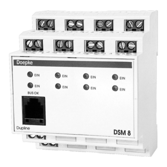
8-fach Relaisausgabe DSM 8
Inhaltsverzeichnis
1. Allgemeines.............................. 2
2. Kodierung................................. 2
3. Inbetriebnahme ........................ 2
4. Anzeigen .................................. 3
5. Technische Daten .................... 3
6. Garantie ................................... 4
Diagram.................................... 8
Dupline
8-way Relay Output DSM 8
Bedienungsanleitung
Operating Instructions
3931182/03/01/D
Table of Contents
7. General Information ................. 5
8. Coding ...................................... 5
9. Putting into Service .................. 5
10. Indicators.................................. 6
11. Technical Data ......................... 6
12. Guarantee ................................ 7
13. Anschlussschema / Connection
Diagram.................................... 8
Advertisement
Table of Contents

Related Manuals for Doepke Dupline DSM 8

Summary of Contents for Doepke Dupline DSM 8
- Page 1 Doepke Dupline 8-fach Relaisausgabe DSM 8 8-way Relay Output DSM 8 Bedienungsanleitung Operating Instructions Inhaltsverzeichnis Table of Contents 1. Allgemeines......2 7. General Information ....5 2. Kodierung......... 2 8. Coding ........5 3. Inbetriebnahme ......2 9. Putting into Service ....5 4.
- Page 2 Doepke Bedienungsanleitung Dupline 8-fach Relaisausgabe DSM 8 1. Allgemeines Das DSM 8 ist eine Komponente des Dupline-Installationssystems und ermöglicht das Schalten von acht Verbrauchern, die an verschiedenen Phasen mit bis zu 16 A betrieben werden dürfen. Insgesamt darf jedoch die Strombelastung 80 A nicht überschreiten.
- Page 3 Doepke Verbindungen zwischen dem Dupline-Signal und der 24 V-Versorgung oder Verbindun- gen zum Erdpotenzial führen zu Störungen und sind nicht zulässig. Auf die richtige Polarität der Versorgungsspannung und des Dupline-Signals ist zu ach- ten. Um den Forderungen für Schutzkleinspannung zu genügen, ist bei der Installation die VDE0100, Teil 410, zu beachten und anzuwenden.
- Page 4 Doepke Min. Typ. Max. Stromaufnahme 135 mA Erlaubte Brummspannung 100 mV Anschlüsse Art Zugbügelklemmen 0,4 mm ∅ Klemmbereich 2,5 mm² Drehmoment 0,6 Nm Gehäuse Art Verteilereinbaugehäuse nach DIN43880 für Hut- schienenmontage nach DIN EN 50022 Maße 72 x 85 x 58 (B x H x T in mm) / 4 TE Material Polycarbonat Allg.
- Page 5 Doepke Operating Instructions Dupline 8-way Relay Output DSM 8 7. General Information The DSM 8 is a component of the Dupline installation system. It permits the switching of eight loads, which may be operated on different phases with up to 16 A. However, the total load may not exceed 80 A The switching status of each output is indicated by a LED on the front of the device.
- Page 6 Doepke Short circuits between Dupline signal conductors and the 24 V operating voltage or con- nections to the grounding lead to malfunction and are not allowed. The correct polarity of operating voltage and Dupline signal conductors has to be ensured.
- Page 7 Doepke Min. Typ. Max. Operating Voltage Rated operating voltage 21.5 VDC 24 VDC 26.5 VDC Current input 135 mA Ripple voltage 100 mV Terminals Type Strain-relief clamps 0.4 mm ∅ Contact area 2.5 mm² Torque 0.6 Nm Housing Type Distribution installation housing to DIN 43880 for...
- Page 8 Doepke 13. Anschlussschema / Connection Diagram L ou t L in L out L i n L ou t L in L out L in L in L ou t L in L ou t L in L ou t...
Need help?
Do you have a question about the Dupline DSM 8 and is the answer not in the manual?
Questions and answers