Table of Contents

Related Manuals for DIGITAL-LOGIC SM800/900DK

Summary of Contents for DIGITAL-LOGIC SM800/900DK
- Page 1 TECHNICAL USER MANUAL FOR: SM800/900DK (Development Kit & Design IN Manual) Nordstrasse 11/F CH - 4542 Luterbach Tel.: ++41 (0)32 681 58 00 Fax: ++41 (0)32 681 58 01 Email: support@digitallogic.com Homepage: http://www.digitallogic.com...
- Page 2 DIGITAL-LOGIC AG. The software described herein, together with this document, are furnished under a license agreement and may be used or copied only in accordance with the terms of that agreement.
-
Page 3: Table Of Contents
DIGITAL-LOGIC AG SM800/900DK Technical Manual V1.2B Table of Contents ..............................5 REFACE 1.1. Trademarks ............................. 5 1.2. Disclaimer ............................5 1.3. Environmental Protection Statement ................... 5 1.4. Who should use this Product ....................... 5 1.5. Recycling Information........................6 1.6. Technical Support .......................... 6 1.7. - Page 4 DIGITAL-LOGIC AG SM800/900DK Technical Manual V1.2B 12.1.4. Mechanical Dimensions of the SM800/900PC/X Receptacle ..........50 12.2. The PCB Orientation of the smart480 Bus................. 51 12.3. The smart480 Bus for the SM800/900PC..................52 12.4. Signal Definitions ......................... 58 12.4.1. Supply Inputs to the Module ....................58 12.4.2.
-
Page 5: Preface
Product advances mean that some specifications may have changed. DIGITAL-LOGIC AG assumes no responsibility for any inaccuracies, or the consequences thereof, that may appear in this manual. Furthermore, DIGITAL-LOGIC AG does not accept any liability arising from the use or application of any circuit or product described herein. -
Page 6: Recycling Information
DIGITAL-LOGIC AG), wrong connection, wrong information or as a result of service or modification by anyone other than DIGITAL-LOGIC AG. Nor if the user has insufficient knowledge of these technologies or has not consulted the product manuals or the technical support of DIGITAL-LOGIC AG and therefore the product has been damaged. -
Page 7: Explanation Of Symbols
DIGITAL-LOGIC AG SM800/900DK Technical Manual V1.2B 1.8. Explanation of Symbols CE Conformity This symbol indicates that the product described in this manual is in compliance with all applied CE standards. Caution, Electric Shock! This symbol and title warn of hazards due to electrical shocks (> 60V) when touching products or parts of them. -
Page 8: Applicable Documents And Standards
DIGITAL-LOGIC AG SM800/900DK Technical Manual V1.2B 1.9. Applicable Documents and Standards The following publications are used in conjunction with this manual. When any of the referenced specifications are superseded by an approved revision, that revision shall apply. All documents may be obtained from their respective organizations. -
Page 9: For Your Safety
1.11. RoHS Commitment DIGITAL-LOGIC AG is committed to develop and produce environmentally friendly products according to the Restriction of Hazardous Substances (RoHS) Directive (2002/95/EC) and the Waste Electrical and Electronic Equipment (WEEE) Directive (2002/96/EC) established by the European Union. -
Page 10: Rohs Compatible Product Design
Components and sub-assemblies are not subject to product compliance. In other words, since DIGITAL-LOGIC does not deliver ready-made products to end users the WEEE directive is not applicable for DIGITAL-LOGIC. Users are nevertheless encouraged to... -
Page 11: Swiss Quality
Network, IQNet, and co-operation contracts/agreements with accredited partners. www.sqs.ch The SQS Certificate ISO 9001:2000 has been issued to DIGITAL-LOGIC AG, the entire company, in the field of development, manufacturing and sales of embedded computer boards, embedded computer modules and computer systems. The certification is valid for three years at which time an audit is performed for... -
Page 12: Overview
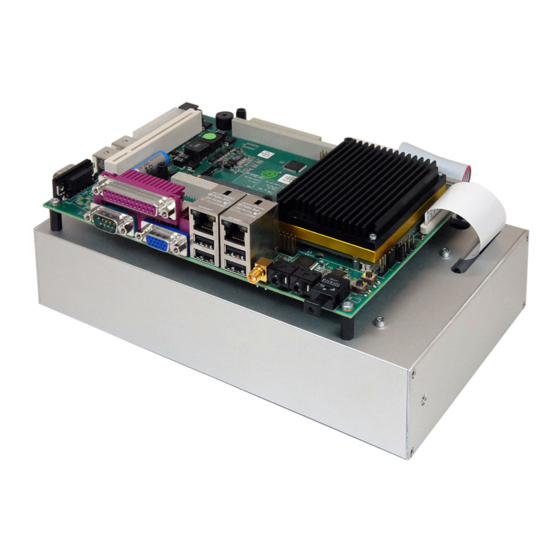
DIGITAL-LOGIC AG SM800/900DK Technical Manual V1.2B 2. O VERVIEW 2.1. Packing List After opening the package, check that the following items are inside the carrying case: 1. The SM800/900 DK: a. an SM800/900 with passive cooler mounted on b. an MSEBX board mounted on c. -
Page 13: Features
DIGITAL-LOGIC AG SM800/900DK Technical Manual V1.2B 2.2. Features External power supply in a metal housing Standard ATX power supply 110/220V 60/50Hz Including 3.5 inch floppy disk SM480 interface to smartModule including SM800/900PC/X Standard PC/AT connectors such as: 2x dual USB... -
Page 14: Block Diagrams
DIGITAL-LOGIC AG SM800/900DK Technical Manual V1.2B 2.3. Block Diagrams 2.3.1. MSEBX800/900... -
Page 15: Sm800/900
DIGITAL-LOGIC AG SM800/900DK Technical Manual V1.2B 2.3.2. SM800/900 2.4. Ordering Information Part / Option Part Nr. Comments SM800DK 805220 Incl. SM800PC and 512MB RAM For current ordering information, please see the current price list. -
Page 16: Specifications
Depth: 150mm Height: Operating Environment Specification Relative Humidity 5 - 90% non-condensing Vibration 5 to 2000Hz Shock Temperature, operating Standard version: -25° C to +70°C Industrial version: -25° C to +85°C (ask DIGITAL-LOGIC AG) Temperature, storage -55° C to +85°C... -
Page 17: System Preparation
DIGITAL-LOGIC AG SM800/900DK Technical Manual V1.2B 3. S YSTEM REPARATION 3.1. Important Information Warning, ESD Sensitive Device! Place the embedded computer board on an isolated, ESD-protected surface. Also ensure that all equipment, tools and people are fully protected against ESD. -
Page 18: Power & Reset Buttons
DIGITAL-LOGIC AG SM800/900DK Technical Manual V1.2B 3.3. Power & Reset Buttons Power Button: Push the Power Button for 2 seconds to start up the system. Reset Button: Should the system hang, press the Reset Button. 3.4. smartModule Replacement 3.4.1. Tools Needed... -
Page 19: Removing The Smartmodule
DIGITAL-LOGIC AG SM800/900DK Technical Manual V1.2B 3.4.2. Removing the smartModule 1. Disconnect the floppy cable (marked as 1 on Photo 1). 2. Disconnect the IDE cable (marked as 2 on Photo 1). 3. Loosen and remove the 4 Phillips head screws at the corners (circled in red and marked "3" on Photo 1, the one marked with an asterisk is almost not visible as it is hidden beneath the IDE cable). - Page 20 DIGITAL-LOGIC AG SM800/900DK Technical Manual V1.2B 5. Lift the MSEBX board and place it upside down as in Photo 2. 6. Loosen and remove the 4 Phillips head screws which are holding the smartModule in place (on the opposite side). These screws are circled in green and marked "6" on Photo 2.
-
Page 21: Mounting The Smartmodule
DIGITAL-LOGIC AG SM800/900DK Technical Manual V1.2B 3.4.3. Mounting the smartModule Basically, reverse the steps mentioned above: 1. Line up the holes in the smartModule on the MSEBX board (top side). Then on the reverse side, attach the smartModule using 4 Phillips head screws (Photo 2, marked "6"). -
Page 22: Description And Location Of The Connectors
DIGITAL-LOGIC AG SM800/900DK Technical Manual V1.2B 4. D ESCRIPTION AND OCATION OF THE ONNECTORS Connector Structure Remarks Power Input Power Jack ATX Power Connector LVDS 2x 10 RM2.54 Video IN 2x 25 RM2.54 MIC IN Phone Jack Line Out Front... -
Page 23: Connector Plan
DIGITAL-LOGIC AG SM800/900DK Technical Manual V1.2B 4.1. Connector Plan... -
Page 24: Connector Descriptions
DIGITAL-LOGIC AG SM800/900DK Technical Manual V1.2B 4.2. Connector Descriptions Power Input Pin Signal Pin Signal 8-30V DC-Input Ground ATX Connector Pin Signal Pin Signal +3.3V +3.3V PWR-OK +5VSB +12V +3.3V -12V PS-ON# LVDS Pin Signal Pin Signal LVDS_A0- LVDS_A0+ LVDS_A1- LVDS_A1+ LCD BKL (dep. - Page 25 DIGITAL-LOGIC AG SM800/900DK Technical Manual V1.2B LCD Connector Pin Signal Pin Signal DE_SPLIT VSYNC HSYNC VCCLCD_SB Ground SHFCLK Ground Ground The LCD interface works only if Jumper J6 is not installed. Microphone Input Audio Connector Pin Signal Pin Signal Sense...
- Page 26 DIGITAL-LOGIC AG SM800/900DK Technical Manual V1.2B X30A Printer Port (Centronics, EMI-Filtered) D-SUB Connector: Signal Pin 1 Strobe Pin 2 Data 0 Pin 3 Data 1 Pin 4 Data 2 Pin 5 Data 3 Pin 6 Data 4 Pin 7 Data 5...
- Page 27 DIGITAL-LOGIC AG SM800/900DK Technical Manual V1.2B PS/2Keyboard (AT Compatible) Pin Signal Pin Signal KB_Data +5Volt / 100mA KB_Clk PS/2Mouse Pin Signal Pin Signal MB_Data +5Volt / 100mA MB_Clk X33A Ethernet LAN RJ-45 Pin Signal RJ-45 Pin Signal X33B / X33C...
- Page 28 DIGITAL-LOGIC AG SM800/900DK Technical Manual V1.2B RJ45 Connector 10BaseT (IEEE 802.3i), 100BaseTX (IEEE 802.3u): MDI-Pin EIA/TIA 568A colors Twisted (wire/line) Pair White / Green Green White / Orange GND .. GND .. Orange GND .. GND .. Cabling: Do not exceed 100m (328 feet); minimum quality of CAT5, preferably S/FTP or STP CAT6.
- Page 29 DIGITAL-LOGIC AG SM800/900DK Technical Manual V1.2B Pin Signal Pin Signal AVR VCC AVR SCL AVR RST AVR MISO AVR MOSI Only for internal use Utility Pin Signal Pin Signal SUSC VCCBat TP PS ON ATX VCC5SB TP System Reset VCC3 TP...
- Page 30 DIGITAL-LOGIC AG SM800/900DK Technical Manual V1.2B 3.5" Hard Disk Pin Signal Pin Signal Reset (active low) (keypin) NC IOW(active low) IOR(active low) IOCHRDY ALE / Master-Slave NC DACK IRQ14 (pri) IRQ15 (sec) IOCS16 (active low) ADR1 DIAG ADR0 ADR2 CS0 (active low)
- Page 31 DIGITAL-LOGIC AG SM800/900DK Technical Manual V1.2B X100 PC/104 Connector (ISA) Pin A: Ground Ground IOCHCK Ground SBHE MEMCS16 RESET LA23 IOCS16 LA22 IRQ10 IRQ9 LA21 IRQ11 LA20 IRQ12 DRQ2 LA19 IRQ15 (-12V) NC LA18 IRQ14 LA17 DACK0 +12V MEMR DRQ0...
- Page 32 DIGITAL-LOGIC AG SM800/900DK Technical Manual V1.2B X101 PC/104+ Connector (PCI) Pin A: GND/5.0V KEY2 Reserved AD00 VI/O AD02 AD01 AD05 AD04 AD03 C/BE0* AD07 AD06 AD09 AD08 AD11 VI/O AD10 M66EN AD14 AD13 AD12 +3.3V C/BE1* AD15 +3.3V SERR* SB0* PERR* +3.3V...
- Page 33 DIGITAL-LOGIC AG SM800/900DK Technical Manual V1.2B X120 MiniPCI Interface Pin Signal Pin Signal Signal Signal RING 3.3V FRAME# 8PMJ-3 8PMJ-1 CLKRUN# TRDY# 8PMJ-6 8PMJ-2 SERR# STOP# 8PMJ-7 8PMJ-4 GROUND 3.3V 8PMJ-8 8PMJ-5 PERR# DEVSEL# LED1_GRNP LED2_YELP C/BE[1]# GROUND LED1_GRNN LED2_YELN...
- Page 34 DIGITAL-LOGIC AG SM800/900DK Technical Manual V1.2B X130 PCI Slot (Standard PCI Slot) Name PCI Pin Description Name PCI Pin Description TRST Test Logic Reset -12V -12 VDC +12V +12 VDC Test Clock Test Mde Select Ground Test Data Input Test Data Output...
-
Page 35: Jumper Locations On The Board
DIGITAL-LOGIC AG SM800/900DK Technical Manual V1.2B 5. J UMPER OCATIONS ON THE OARD The following tables show the location of the jumper blocks on the MSEBX800/900 board. The numbers shown in these tables are silk screened on the board so that the pins can be easily located. This chapter refers to the individual pins for these jumpers. -
Page 36: Jumpers On The Msebx800
DIGITAL-LOGIC AG SM800/900DK Technical Manual V1.2B 5.3. Jumpers on the MSEBX800... -
Page 37: Led Type, Reference And Function
DIGITAL-LOGIC AG SM800/900DK Technical Manual V1.2B 5.4. LED Type, Reference and Function Hard Disk LEDs Type RED LED Reference D15: 2.5" HDD connector D17: 3.5" HDD connector Function Show hard disk access Ethernet LAN LEDs (for the ER82551ER controller integrated on the Development Kit) -
Page 38: Driver Installation
DIGITAL-LOGIC AG SM800/900DK Technical Manual V1.2B 6. D RIVER NSTALLATION Please refer to the GEODE_LX800-900 manual. 7. S OFTWARE Please refer to the GEODE_LX800-900 manual. 8. S PECIAL ERIPHERALS ONFIGURATIONS OFTWARE Please refer to the GEODE_LX800-900 manual. 9. BIOS Please also refer to the GEODE_LX800-900 manual. -
Page 39: Core Bios Download
DIGITAL-LOGIC AG SM800/900DK Technical Manual V1.2B 9.1. Core BIOS Download Before downloading a BIOS, please check the following: Make a bootable diskette which includes the following files: Flashrom.com core BIOS xxxxxxxx.yyy IMPORTANT: Do not use boot disks created in a Windows operating system. If you do not have an MSDOS 6.22 disk available, you can download a boot disk from www.bootdisk.com... -
Page 40: Bios Recovery
DIGITAL-LOGIC AG SM800/900DK Technical Manual V1.2B 9.2. BIOS Recovery In case the BIOS needs to be recovered: 1. Set Jumper J9. 2. Start the MSEBX800/900. 3. Open the BIOS. 4. Remove Jumper J9. 5. Load the default BIOS settings. 6. Save the settings. -
Page 41: Diagnostics
DIGITAL-LOGIC AG SM800/900DK Technical Manual V1.2B 10. D IAGNOSTICS 10.1. Post Codes DIGITAL-LOGIC LX800/900 Post Codes Info: Informational code only Error: Error code. The system halts Info/Error: Informational code but the system can halt. Checkpoint Description Type Initialize CS5536 specific registers... - Page 42 DIGITAL-LOGIC AG SM800/900DK Technical Manual V1.2B Checkpoint Description Type Scan PCI bus and assign resources Info Scan PCI bus for devices Assign BAR and Interrupt Scan and Initialize option ROMs Info Configure IT8888 Bridge Find and call all option ROMS from C800:0 to DFF0:0...
- Page 43 DIGITAL-LOGIC AG SM800/900DK Technical Manual V1.2B Checkpoint Description Type Unsupported DIMM. (e.g. registered, buffered or asymmetric density) Info* => See Post 7Fh Unsupported number of banks on DIMM Info* => See Post 7Fh Memory setup successful Info Memory setup failed.
- Page 44 DIGITAL-LOGIC AG SM800/900DK Technical Manual V1.2B Checkpoint Description Type 0B0h Starting memory test Info 0B1h Reading 64 bytes from memory Info 0B2h Writing 64 bytes to memory Info 0B3h Read and compare 64 bytes of memory Info 0B4h Walk Memory by x^2...
-
Page 45: Smart Module Accessible Dk Features
DIGITAL-LOGIC AG SM800/900DK Technical Manual V1.2B DK F SMART ODULE CCESSIBLE EATURES The following table shows the available functionalities of the Development Kit and the different modules so the customer can know precisely which smartModule type can be used for each DK function. -
Page 46: Design -I N With The Smart Module
DIGITAL-LOGIC AG SM800/900DK Technical Manual V1.2B 12. D ESIGN ITH THE SMART ODULE 12.1. Mechanical Dimensions of the SM800/900PC/X... -
Page 47: Mechanical Pcb Pad Dimensions On The Carrier Board
DIGITAL-LOGIC AG SM800/900DK Technical Manual V1.2B 12.1.1. Mechanical PCB Pad Dimensions on the Carrier Board... -
Page 48: Pcb To Sm800/900Pc/X Height
DIGITAL-LOGIC AG SM800/900DK Technical Manual V1.2B 12.1.2. PCB to SM800/900PC/X Height... -
Page 49: Mechanical Dimensions Of The Pcb Plug
DIGITAL-LOGIC AG SM800/900DK Technical Manual V1.2B 12.1.3. Mechanical Dimensions of the PCB Plug The PCB plug must be mounted onto the customer’s electronic board (carrier board). Custom height: 5.0mm SM480-CON5 DLAG part number: 807125 (do not place components below the smartModule) Standard height: 7.0mm... -
Page 50: Mechanical Dimensions Of The Sm800/900Pc/X Receptacle
DIGITAL-LOGIC AG SM800/900DK Technical Manual V1.2B 12.1.4. Mechanical Dimensions of the SM800/900PC/X Receptacle Mounted on the smartModule800PC only as a reference. Dimension (inches) 52760-2409 Circuits 84.07 (3.309) 75.565 (2.970) 80.47 (3.168) 78.87 (3.105) DLAG part number: 439003... -
Page 51: The Pcb Orientation Of The Smart480 Bus
DIGITAL-LOGIC AG SM800/900DK Technical Manual V1.2B 12.2. The PCB Orientation of the smart480 Bus The two bus connectors X200B and X200A are located on the PCB (motherboard). Two signals are specified to simplify the compare and the checks. Refer to chapter 12.1.1 for the dimensions of all drill and screw holes. -
Page 52: The Smart480 Bus For The Sm800/900Pc
DIGITAL-LOGIC AG SM800/900DK Technical Manual V1.2B 12.3. The smart480 Bus for the SM800/900PC SM800/900PCX Connector X200.A Pins 1-40 Group Volt Description Group Volt Description POWER VCC (5V) RESDRV IRQ9 SBHE# IRQ3 MEMCS16# IRQ4 IOCS16# IRQ5 IOW# IRQ6 IOR# IRQ7 SYSCLK... - Page 53 DIGITAL-LOGIC AG SM800/900DK Technical Manual V1.2B SM800/900PCX Connector X200.A Pins 41-80 Group Volt Description Group Volt Description TINY CORE Speaker TINY MISO ZWS# TINY MOSI / StartMode ** REF# TINY MEMR# TINY VCC_PROG SMEMR# LAD0 MEMW# LAD1 SMEMW# LAD2 VIDEO IN...
- Page 54 DIGITAL-LOGIC AG SM800/900DK Technical Manual V1.2B SM800/900PCX Connector X200.A Pins 81-120 Group Volt Description Group Volt Description POWER GROUND POWER GROUND POWER GROUND POWER GROUND POWER GROUND A100 B100 A101 B101 A102 B102 A103 B103 A104 B104 A105 B105 A106...
- Page 55 DIGITAL-LOGIC AG SM800/900DK Technical Manual V1.2B SM800/900PCX Connector X200.B Pins 1-40 Group Volt Description Group Volt Description PRINTER strobe# COM1 DCD1 PRINTER auto# COM1 DSR1 PRINTER error# COM1 RXD1 PRINTER init# COM1 RTS1 PRINTER slctin# COM1 TXD1 PRINTER 5 i/o PRINTER data 0...
- Page 56 DIGITAL-LOGIC AG SM800/900DK Technical Manual V1.2B SM800/900PCX Connector X200.B Pins 41-80 Group Volt Description Group Volt Description HD_DACK# IrDA IrDA TX HD_DREQ# IrDA IrDA RX 5tol i HD_IRQ HD_IOR# HD_IOW# POWER VCC (5V) POWER Battery 3.0V for RTC 3 i/o AD0...
- Page 57 DIGITAL-LOGIC AG SM800/900DK Technical Manual V1.2B SM800/900PCX Connector X200.B Pins 81-120 Group Volt Description Group Volt Description USB1 5 i/o USB_P1+ USB1 5 i/o USB_P1- LA22 LA23 5 i/o PERR- GPIO I/OD12ttl GPIO30 GPIO I/OD12ttl GPIO31 3 i/o SMB-DAT GPIO...
-
Page 58: Signal Definitions
DIGITAL-LOGIC AG SM800/900DK Technical Manual V1.2B 12.4. Signal Definitions 12.4.1. Supply Inputs to the Module Power Inputs to the SM800/900 Signals Value/Function Comment Remark 1 Remark 2 VCC5SB 5.0V input 0.2A Connect a 100nF to each pin 5.0V input 1.5A... -
Page 59: Reset Inputs Of The Module
The LPC Bus is used to connect a secondary SuperIO chip, for an optional firmware hub and for the POD80 port. We recommend connecting all LPC signals to, at minimum, a 10pin header. Please see the sample schematics. DIGITAL-LOGIC provides an LPC-POD analyzer to display the POD codes from the BIOS. The LPC-Bus is length sensitive (maximum 20cm). -
Page 60: Pm Controller In-Circuit Programming Signals
DIGITAL-LOGIC AG SM800/900DK Technical Manual V1.2B 12.4.8. PM Controller In-Circuit Programming Signals The micro-controller may be programmed in-circuit. ICP of the SM800/900 Signals Value/Function Used for If used If not used TINY: PM Controller Recommended to Don’t connect SCL,MISO,MOSI, connect these signals... -
Page 61: Smb/I2C Bus Of The Module
DIGITAL-LOGIC AG SM800/900DK Technical Manual V1.2B 12.4.12. SMB/I2C Bus of the Module The I2C Bus is used internally for the LM75 thermosensor and the programming of the PLL. Both signals are internally pulled up to 3.3V. SMB-Bus of the SM800/900... -
Page 62: Gpioxx Interface Of The Module
DIGITAL-LOGIC AG SM800/900DK Technical Manual V1.2B 12.4.16. GPIOxx Interface of the Module The GPIO interfaces are freely programmable, general purpose IOs (see Section 13.7.10). They are internally connected directly to the SuperIO W83627HF from Winbond. GPIO Interface of the SM800/900... -
Page 63: Ide Interface Of The Module
DIGITAL-LOGIC AG SM800/900DK Technical Manual V1.2B 12.4.20. IDE Interface of the Module The IDE interface is provided by the CS5536 on-module. IDE-Interface of the SM800/900 Signals Value/Function Used for If used If not used 5Vtol / 3V out Connect to IDE connector. -
Page 64: Floppy-Interface Of The Module
DIGITAL-LOGIC AG SM800/900DK Technical Manual V1.2B 12.4.23. Floppy-Interface of the Module The Floppy. Interface are provided by the SuperIO onmodule. See the sample schematics. FDC-Interface of the SM800/900 Signals Value/Function Used for If used If not used TTL 5V in / Connect all signals to Don’t connect... -
Page 65: Lcd Interface Signal / Color Definition
DIGITAL-LOGIC AG SM800/900DK Technical Manual V1.2B 12.4.25. LCD Interface Signal / Color Definition B119 FPM (out) A106 CRT: Vert. Synch VSYNC VSYNC A119 Enable BKL (TTL out) B106 CRT: Horiz. Synch HSYNC HSYNC A120 VCC 3.3V B105 Shift Clock B104 Enable VDD (TTL out) -
Page 66: Design Rules For Integration
DIGITAL-LOGIC AG SM800/900DK Technical Manual V1.2B 13. D ESIGN ULES FOR NTEGRATION There are many very fast interfaces on this product. Some of these interfaces are working differentially and must be routed in twisted pair with equal flight times. All power signals must be designed as power planes including all decoupling capacitors. The power planes... -
Page 67: Start Up/Power Off Procedure
DIGITAL-LOGIC AG SM800/900DK Technical Manual V1.2B 13.1. Start up/Power off Procedure VCCSB = VCCSUS must be present in order to start the SM800/900PC/X. By factory default the SM800/900PC/X automatically powers-on by setting the SUSC# signal low and requesting the base board to turn on the main power supply. -
Page 68: The Atx-Power For Vcc
DIGITAL-LOGIC AG SM800/900DK Technical Manual V1.2B 13.1.3. The ATX-Power for VCC The VCC is generated from the VCC5SB with a FET. Refer to the sample schematics for how to implement the FET in detail. With SUSC# the FET must be ON (low resistance). The SUSC# pulls down for stopping the VCC. -
Page 69: Power Planes
DIGITAL-LOGIC AG SM800/900DK Technical Manual V1.2B 13.1.4. Power Planes Use a plane for all power signals. Place decoupling capacitors on each power plane as referred to in the following table: Power Input to the SM800/900 Power plane for power input to SM800/900... -
Page 70: Integration Checklist
DIGITAL-LOGIC AG SM800/900DK Technical Manual V1.2B 13.2. Integration Checklist The most important input to control the computer system is: PWRBTN#: input of the SM800/900PC with the function of a main power switch: If the system is OFF: 0.3sec activating (to GND) starts the system... - Page 71 DIGITAL-LOGIC AG SM800/900DK Technical Manual V1.2B SuperIO-Signal: Checkpoint Part and Signal level, Signal level, Signal level, Pin-Nr when powered 2 sec after in S3, after DCMAIN, but MAIN_SW activating MAIN_SW not activated, PWRBTN# activated. in S0 COM1 and COM2 input...
-
Page 72: Pci-Bus
DIGITAL-LOGIC AG SM800/900DK Technical Manual V1.2B 13.3. PCI-Bus 13.3.1. PCI Bus Signals The smartModule only supports 3.3V PCI. 3.3V is generated on the SM800/900PCX; 1A can be used for peripherals on the base board. A 5V 2A supply to the SM800/900PCX is sufficient. -
Page 73: Pci Signal Descriptions
DIGITAL-LOGIC AG SM800/900DK Technical Manual V1.2B 13.3.3. PCI Signal Descriptions Name Type Voltage Description Address/Data. The standard PCI address and data lines. The address is AD[31:0] I/O PCI +3.3 driven with FRAME# assertion, and data is driven or received in ensuing clocks. -
Page 74: Pci Slot Assignment
DIGITAL-LOGIC AG SM800/900DK Technical Manual V1.2B PCI Signal Descriptions (continued) Name Type Voltage Description STOP# I/O PCI +3.3 PCI Stop. As an input, STOP# indicates that a PCI slave wants to terminate the current transfer. The transfer is either aborted or retried. STOP# is also used to end a burst. -
Page 75: Clocks
DIGITAL-LOGIC AG SM800/900DK Technical Manual V1.2B 13.4. Clocks 13.4.1. Clock Layout Guidelines Series matching resistors are required. Not used PCI_CLK[1:0] signals should be loaded by 47pF to reduce the EMI noise. Resistor Value: 10 Ohms in series are recommended for better EMI results. -
Page 76: Isa Bus Signals
DIGITAL-LOGIC AG SM800/900DK Technical Manual V1.2B 13.6. ISA Bus Signals With Version 2.x of the sm800PCX, the full ISA Bus is supported. ISA Signal Resistors Values, (onboard of smartModule integrated) Name Termination Resistor ( ) Pull-up (pull-down) Resistor ( ) -
Page 77: Interfaces
DIGITAL-LOGIC AG SM800/900DK Technical Manual V1.2B 13.7. Interfaces 13.7.1. USB Interface For the USB ports, it is recommended to place an overvoltage protection and an EMI-filter inductor on each signal line directly at the USB-connector. Since USB2.0 works with high frequencies, the two data lines of the USB interface must be length-compensated to a difference smaller than 1mm. - Page 78 DIGITAL-LOGIC AG SM800/900DK Technical Manual V1.2B 13.7.1.1. Roules for designing highspeed differential signals:...
-
Page 79: Lan Signals
DIGITAL-LOGIC AG SM800/900DK Technical Manual V1.2B 13.7.2. LAN Signals Component placement can affect signal quality, emissions, and temperature of a board design. Decrease potential problems directly related to electromagnetic interference (EMI), which could cause failure to meet FCC. Simplify the task of routing traces. To some extent, component orientation will affect the complexity of. - Page 80 DIGITAL-LOGIC AG SM800/900DK Technical Manual V1.2B 13.7.2.1. PHY Interface Circuit with Integrated Magnetics...
- Page 81 DIGITAL-LOGIC AG SM800/900DK Technical Manual V1.2B The LAN connector J1012F21 from PULSE with integrated magnetics:...
-
Page 82: Ide Interface
DIGITAL-LOGIC AG SM800/900DK Technical Manual V1.2B 13.7.3. IDE Interface The LX800/900 supports only one IDE port, assigned as the primary IDE port. The IDE signals are 3.3V output and 5Volt tolerant inputs in the CD5536. pull-down resistors on Pin28 of the IDE connector (ALE). Support cable select (ALE) is a PC97 requirement. -
Page 83: Serial Com1/2 Interface
DIGITAL-LOGIC AG SM800/900DK Technical Manual V1.2B 13.7.4. Serial COM1/2 Interface The sm800/900PCX provides the TTL serial signals. The RS232-converter is not integrated. Use a MAX211, or similar converter, for V24/RS232C interfaces. Use 4x470nF as pump-capacitors for the MAX211. 100nF are not enough over the extended temperature range. -
Page 84: Ac'97 Sound Interface
DIGITAL-LOGIC AG SM800/900DK Technical Manual V1.2B 13.7.9. AC’97 Sound Interface The sm800/900PCX provides an AC’97 interface with 3.3V. The BITCLK should have a 33 Ohm series resistor to reduce the EMI noise. Place the AC’97 device as close as possible to the sm480bus. -
Page 85: Programming The Gpio30/31/34 Signals
DIGITAL-LOGIC AG SM800/900DK Technical Manual V1.2B 13.7.10. Programming the GPIO30/31/34 signals While the BIOS, the status and direction of this signals may be defined in the BIOS-Settings. After the BIOS has executed INT19 and bootup the OS, the application may control these signals by programming the SuperIO. - Page 86 DIGITAL-LOGIC AG SM800/900DK Technical Manual V1.2B ;----------------------------------------------------------------------------- ; Configurate logical device 9 (GPIO3) ;----------------------------------------------------------------------------- MOV DX,2EH MOV AL,07H OUT DX,AL ; point to Logical Device Number Reg. MOV DX,2FH MOV AL,09H OUT DX,AL ; select logical device 9 (GPIO3) MOV DX,2EH...
- Page 87 DIGITAL-LOGIC AG SM800/900DK Technical Manual V1.2B ;CRF2 (GP30-GP35 inversion register. Bit 7-6: Reserve) ;When set to a '1', the incoming/outgoing port value is inverted. ;When set to a '0', the incoming/outgoing port value is the same as in data register.
-
Page 88: Schematics Sm800/900Pc Development Kit
DIGITAL-LOGIC AG SM800/900DK Technical Manual V1.2B 14. S SM800/900PC D CHEMATICS EVELOPMENT The following pages show some sample schematics for the SM800/900PC Development Kit. The Product CD includes the necessary schematics. - Page 89 DIGITAL-LOGIC AG SM800/900DK Technical Manual V1.2B...
- Page 90 DIGITAL-LOGIC AG SM800/900DK Technical Manual V1.2B...
- Page 91 DIGITAL-LOGIC AG SM800/900DK Technical Manual V1.2B...
- Page 92 DIGITAL-LOGIC AG SM800/900DK Technical Manual V1.2B...
- Page 93 DIGITAL-LOGIC AG SM800/900DK Technical Manual V1.2B...
- Page 94 DIGITAL-LOGIC AG SM800/900DK Technical Manual V1.2B...
- Page 95 DIGITAL-LOGIC AG SM800/900DK Technical Manual V1.2B...
- Page 96 DIGITAL-LOGIC AG SM800/900DK Technical Manual V1.2B...
- Page 97 DIGITAL-LOGIC AG SM800/900DK Technical Manual V1.2B...
- Page 98 DIGITAL-LOGIC AG SM800/900DK Technical Manual V1.2B...
- Page 99 DIGITAL-LOGIC AG SM800/900DK Technical Manual V1.2B...
- Page 100 DIGITAL-LOGIC AG SM800/900DK Technical Manual V1.2B...
- Page 101 DIGITAL-LOGIC AG SM800/900DK Technical Manual V1.2B...
-
Page 102: Index
DIGITAL-LOGIC AG SM800/900DK Technical Manual V1.2B 15. I NDEX Disclaimer ............5 DK Features ............45 Driver Installation ..........38 AC97 Bus AC97 Bus ............60 ATX-Power ............68 ATX-START Mode..........67 Environmental Protection Statement ....5 AUTOSTART Mode ..........67 Features ............. 13 BIOS ..............38... - Page 103 DIGITAL-LOGIC AG SM800/900DK Technical Manual V1.2B PCI Bus............61 PM Controller..........60 PS2 Interface........... 62, 63 PCB Pad Dimensions .........47 Reset Inputs ..........59 PCB Plug ............49 Reset Outputs..........58 PCB to smartModule Height .......48 SMB/I2C Bus ..........61 PCI Signal Descriptions ........73 Supply Inputs ..........
Need help?
Do you have a question about the SM800/900DK and is the answer not in the manual?
Questions and answers