Table of Contents
Advertisement
Advertisement
Table of Contents

Related Manuals for schildknecht DATAEAGLE X-TREME 3 Series


Summary of Contents for schildknecht DATAEAGLE X-TREME 3 Series
- Page 1 Installation and commissioning manual Wireless Profibus System DATAEAGLE® 3XXX X-treme Schildknecht AG D -71711 Murr – Haugweg 26 Phone +49 (0)7144 89718-0 - Fax +49 (0) 7144 8971829 Email: office@schildknecht.ag - Internet: www.schildknecht.ag DATAEAGLE 3XXX X-treme Version: 14.04.2020...
-
Page 2: Introduction
Warranty Schildknecht AG can ac- cept no liability for indi- rect damage or direct damage, incidental dam- age, consequential dam- age or compensation for... - Page 3 Any questions? First, have a look in the table of contents. You will quickly find what you are looking for. If you do need us in person: just call us or send a fax: Schildknecht AG Haugweg 26 D -71711 Murr...
-
Page 4: Table Of Contents
Table of contents Page Introduction 1. General information 1.1. Guide to symbols 1.2. Copyright and brand names 1.3. Declaration of conformity and EC directives 2. Safety instructions 2.1. Intended use 2.2. General information 2.3. Installations instructions 2.4. Safety instructions for operation 2.5. - Page 5 5.3.3. Install new module 5-21 5.3.4. Start Dataeagle Wizard 5-22 5.3.5. Procedure for exchanging radio modules 5-23 5.3.6. Example 1: Exchange of a Radio Slave 5-24 5.3.7. Example 2: Exchange of a Radio Master 5-31 5.4. Profibus-Slave-Addresses 5-47 5.4.1. Procedure for exchanging a Radio Master before de-installation 5-48 5.4.2.
-
Page 6: General Information
XP and Microsoft Internet Explorer are registered trademarks of Microsoft Corp. Adobe Reader is a registered trademark of Adobe Systems Corp. DATAEAGLE® is a registered trademark of Schildknecht AG. 1.3. Declaration of conformity and EC directives Information about the declaration of conformity and about EC directives can be found under: http://www.schildknecht.ag/download/dataeagle-konformitaetserklaerung... -
Page 7: Safety Instructions
Chapter 2 - Safety instructions 2. Safety instructions 2.1. Intended use Information about the intended use can be found in the oper- ating instructions wireless data systems DATAEAGLE. 2.2. General information In order to guarantee safe use and fault-free operation, the according safety instructions have to be observed under all circumstances. -
Page 8: Installations Instructions
Do not repair the module yourself, replace it with an equivalent module. Repairs may only be carried out by the Schildknecht AG. The Schildknecht AG is not liable for damage resulting from a failure to comply. -
Page 9: Personnel Qualification
Chapter 2 - Safety instructions 2.5. Personnel qualification Only qualified personnel may carry out the following tasks: Installation Commissioning Operation Maintenance Within the context of safety regulations, qualified personnel are individuals authorized to commission, to ground, and to identify equipment and systems in accordance with the safety-engineering standards. -
Page 10: Structure
Chapter 3 – Structure 3. Structure 3.1. System description The system is used for the wireless Profibus transmission. It consists of a radio master and up to 4 radio slaves (de- pending on the device type). The module can have up to 8 Profibus slaves (depending on the device type). -
Page 11: Radio Module
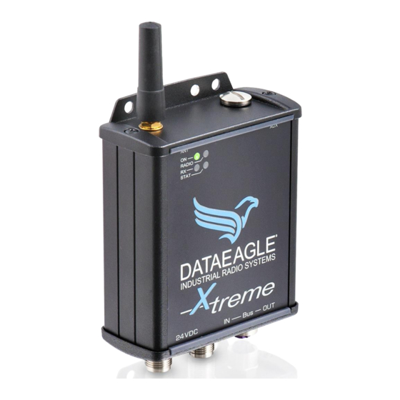
Chapter 3 – Structure 3.2. Radio module The radio module transmits the signals via radio and is avail- able in two radio technologies. Type Radio technology Transmission Profibus Profibus Radio power Slaves Slaves 3712 2,4 GHz Bluetooth 100 mW bis 1,5 MBit max. - Page 12 Chapter 3 – Structure Structure and connections of the radio module: connection (configuration) Antenna connection Power supply +24V,GND,PE PROFIBUS- IN PROFIBUS- Status-LEDs Installation and commissioning DATAEAGLE 3XXX X-treme...
- Page 13 Chapter 3 – Structure Status-LEDs Die Tabelle zeigt die Bedeutung der LEDs am Funkmodul: Name Colour Function Green Power ok RADIO Blue DE37XX: Bluetooth connection established DE33XX: On or flashing when connected Yellow Receiving radio data STAT Status display at Dataeagle Master On: no reception of PROFIBUS telegrams Flashing: Error (one of the connected DP participants is...
- Page 14 Kapitel 3 – Aufbau Connection of The figure shows the pin assignment of the plugs power supply (view towards the module): and PROFIBUS Power supply (plug) M12 A coding Pin 1: +9-33VDC Pin 2: Pin 3: Pin 4: Pin 5: PROFIBUS IN (plug) PROFIBUS OUT (sleeve) M12 B coding...
-
Page 15: Installation Of New Devices
Chapter 4 – Installation of new devices 4. Installation of new devices Please be certain to read the guidelines in chapter 7 „Tips and Tricks – improvement of the electromagnetic compatibility (EMC)“. Observe these guidelines during the complete installation procedure. Thereby you avoid electromagnetic interferences and you improve the data transmission quality. -
Page 16: Install Radio Module
Drill the fastening holes. Use therefore the drill template (not drawn to scale): You may find the true-to-scale drill template on the provided CD ROM: http://www.schildknecht.ag/download/x-treme-drill-template-bohrschablone/ Fasten the radio module. Installation and commissioning DATAEAGLE 3XXX X-treme... -
Page 17: Install Antenna Cable
Chapter 4 – Installation of new devices 4.3. Install antenna cable Connect the antenna cable to the antenna connection of the radio module. CAUTION The radio module may be damaged if the antenna cable is fastened too tight. Connect the antenna cable only hand-tight. ... -
Page 18: Connect Profibus Plug
Chapter 4 – Installation of new devices 4.4. Connect PROFIBUS plug Connect the PROFIBUS plug. 4.5. Connect power supply Connect the power supply. For an optimum tightness it is recommended to tighten the plugs with a torque of 0.6 Nm (use a suited torque wrench). - Page 19 Chapter 4 – Installation of new devices CAUTION PE has to be connected with control cabinet round! If the PE is not connected the noise filter cannot filter interfer- ences on 9-33V DC power supply line. These may cause malfunctions, errors or the destruction of the device. Supply source needs to be in compliance with SELV and LPS output according UL/IEC 60950-1 or ES1 and PS2 output according UL/IEC 62368-1.
-
Page 20: Extension And Exchange
Chapter 5 – Extension and exchange 5. Extension and exchange If the system is extended or if modules are exchanged the modules must be newly configured after installation. There- fore the USB drivers and the software Dataeagle Wizard must be installed on your PC and the radio module has to be connected to the PC. -
Page 21: Microsoft Internet Explorer
Chapter 5 – Extension and exchange 5.1.3. Microsoft Internet Explorer To ensure a safe function it is important that you define Mi- crosoft Windows Explorer as standard browser before you in- sert the CD ROM into the drive. Only when Microsoft Internet Explorer is not the stand- ard browser: ... -
Page 22: Install Usb Drivers
USB drivers. Insert the CD in your CD-ROM drive. The browser shows the available documents and down- loads for all Schildknecht products. Scroll until you find your product, e.g. DATAEAGLE X- treme 3712. ... - Page 23 Chapter 5 – Extension and exchange The available files/applications are shown. Start the application „CDM v2.12.00 WHQL Certified“ (Double click). The following message appears: Click on „Alle extrahieren“. Mark the application „CDM v2.12.00 WHQL Certified“ with the right mouse key.
- Page 24 Chapter 5 – Extension and exchange Click on „Extract“. The installation wizard is started: Click on „Weiter“. The license agreement is shown. Installation and commissioning DATAEAGLE 3XXX X-treme...
- Page 25 Chapter 5 – Extension and exchange Click on „Weiter“. The USB drivers are loaded. Click on „Fertig stellen“. The USB drivers are now installed. Use the "Auto-detect COM-Port" function of the Dataeagle Wizard to establish a USB connection to the radio module. Installation and commissioning DATAEAGLE 3XXX X-treme...
-
Page 26: Install Dataeagle Wizard
Load Dataeagle Wizard from the CD: Select your product in the browser, e.g. DATAEAGLE X-treme 3713. Click on Load Dataeagle Wizard from the homepage: http://www.schildknecht.ag/download/konfiguration-und-diagnosesoftware Start download. Open an unpack file. Installation and commissioning DATAEAGLE 3XXX X-treme... - Page 27 Chapter 5 – Extension and exchange Start Setup The installation program is started. Click on „Install“. The program is loaded and started: Installation and commissioning DATAEAGLE 3XXX X-treme...
-
Page 28: Extension
Chapter 5 – Extension and exchange 5.2. Extension There are two ways to extend the radio system: An additional Profibus Slave is connected to an existing Radio Slave. An additional Radio Slave is integrated into the radio system. 5.2.1. - Page 29 Installation and commissioning DATAEAGLE 3XXX X-treme...
-
Page 30: Start Dataeagle Wizard
Chapter 5 – Extension and exchange 5.2.3. Start Dataeagle Wizard Start the Dataeagle Wizard. The Dataeagle Wizard is stored in the folder „Schildknecht AG“ during installation. The start screen appears: Installation and commissioning DATAEAGLE 3XXX X-treme... -
Page 31: Configure Radio Master
Chapter 5 – Extension and exchange 5.2.4. Configure Radio Master Remove the screw cap. Connect the Radio Master with an USB cable to the Click on „Connect“. Installation and commissioning DATAEAGLE 3XXX X-treme... - Page 32 Chapter 5 – Extension and exchange After the radio module is detected the following message ap- pears: Acknowledge with „OK“. The Radio Master is shown, e.g. Dataeagle 3712A Master. Installation and commissioning DATAEAGLE 3XXX X-treme...
- Page 33 Chapter 5 – Extension and exchange Display addresses Double-click on the device name, then double-click on „Radio“. The radio module addresses are shown: In this example the radio system consists of one Radio Mas- ter with address 01 and two Radio Slaves with the addresses 02 and 03.
- Page 34 Chapter 5 – Extension and exchange Add new Click on „Add“. address Enter the new address, e.g. 4 and click „OK“. The new Radio Slave address is shown Installation and commissioning DATAEAGLE 3XXX X-treme...
- Page 35 Chapter 5 – Extension and exchange Display Channel/ Click once on „869 MHz“ (for DATAEAGLE X-TREME Bluetooth MAC 33XX) or once on „Bluetooth“ (for DATAEAGLE X- Address TREME 37XX). The set channel or the Bluetooth MAC address is shown: ...
-
Page 36: Configure Radio Slave
Chapter 5 – Extension and exchange 5.2.5. Configure Radio Slave Connect the Radio Slave with an USB cable to the PC. Click on „Connect“. Acknowledge with „OK“. The Radio Slave is shown, e.g. Dataeagle 3712A Slave. Installation and commissioning DATAEAGLE 3XXX X-treme... - Page 37 Chapter 5 – Extension and exchange Enter addresses Double-click on the device name and then double-click on „Radio“. The radio module addresses are shown: Enter the correct addresses. The Radio Master has the station address 01 and partner ad- dress 04 was assigned to the new radio module.
- Page 38 Chapter 5 – Extension and exchange Enter Chanel/ Click once on „869 MHz“ (for DATAEAGLE X-TREME Bluetooth MAC 33XX) or once on „Bluetooth“ (for DATAEAGLE X- Address TREME 37XX). The channel or the Bluetooth MAC address is shown: Enter the channel or the Bluetooth MAC address you have noted before.
-
Page 39: Exchange
Chapter 5 – Extension and exchange 5.3. Exchange The exchange of a module is carried out according to the procedure shown below: Remove the wiring Remove the old module Install unit on top-hat rail Connect antenna cable ... -
Page 40: Remove Wiring
Chapter 5 – Extension and exchange 5.3.1. Remove wiring Remove the power supply. Remove the PROFIBUS plug. Remove the antenna cable. 5.3.2. Remove old module Loosen the fastening screws and remove the module. 5.3.3. Install new module ... -
Page 41: Start Dataeagle Wizard
No configuration with the Dataeagle Wizard is necessary when an I/O module has been exchanged. Start the Dataeagle Wizard. The Dataeagle Wizard is stored in the folder „Schildknecht AG“ during installation. The start screen appears: Installation and commissioning DATAEAGLE 3XXX X-treme... -
Page 42: Procedure For Exchanging Radio Modules
Chapter 5 – Extension and exchange 5.3.5. Procedure for exchanging radio modules The further procedure depends on the type of the radio mod- ule (DATAEAGLE X-TREME 33XX with 869 MHz or DA- TAEAGLE X-TREME 37XX Bluetooth) and whether a Radio Master or a Radio Slave have been exchanged. -
Page 43: Example 1: Exchange Of A Radio Slave
Chapter 5 – Extension and exchange 5.3.6. Example 1: Exchange of a Radio Slave Overview Connect Radio Master to Wizard Read off Radio Master address Determine address of the exchanged Radio Slave Connect Radio Slave to Wizard ... - Page 44 Chapter 5 – Extension and exchange Click on „Connect“. After the radio module is detected the following message ap- pears: Acknowledge with „OK“. The Radio Master is shown, e.g. Dataeagle 3712A Master. Installation and commissioning DATAEAGLE 3XXX X-treme...
- Page 45 Chapter 5 – Extension and exchange Display address Double-click on the device name and then double-click on „Radio“. The radio module addresses are shown: In this example the radio system consists of one Radio Mas- ter with address 01 and three Radio Slaves with the ad- dresses 02, 03 and 04.
- Page 46 Chapter 5 – Extension and exchange Display channel/ Click once on „869 MHz“ (for DATAEAGLE X-TREME Bluetooth MAC 33XX) or on address „Bluetooth“ (for DATAEAGLE X-TREME 37XX). The set channel or the Bluetooth MAC address is shown: Note the channel, e.g. Channel 1 or the Bluetooth MAC address, e.g.
- Page 47 Chapter 5 – Extension and exchange Configure Radio Connect the newly installed Radio Slave with an USB Slave cable to the PC. Click on „Connect“. Acknowledge with „OK“. The Radio Slave is shown, e.g. Dataeagle 3712A Slave. Installation and commissioning DATAEAGLE 3XXX X-treme...
- Page 48 Chapter 5 – Extension and exchange Enter addresses Double-click on the device name and then double-click on „Radio“. The radio module addresses are shown: Enter the correct addresses. The Radio Master has the station address 01 and the ex- changed radio module has the partner address 03.
- Page 49 Chapter 5 – Extension and exchange Enter Chanel/ Click once on „869 MHz“ (for DATAEAGLE X-TREME Bluetooth MAC 33XX) or once on „Bluetooth“ (for DATAEAGLE X- Address TREME 37XX). The channel or the Bluetooth MAC address is shown: Enter the channel or the Bluetooth MAC address you have noted before.
-
Page 50: Example 2: Exchange Of A Radio Master
Chapter 5 – Extension and exchange 5.3.7. Example 2: Exchange of a Radio Master Overview Connect Radio Slave to Wizard Read off Radio Master and Radio Slave addresses Exchange of DATAEAGLE Exchange of DATAEAGLE X-TREME 333X X-TREME 37XX (869 MHz) (Bluetooth) Read off channel... - Page 51 Chapter 5 – Extension and exchange Remove the screw cap. Connect the Radio Slave with the USB cable to the PC. Click on „Connect“ Installation and commissioning DATAEAGLE 3XXX X-treme...
- Page 52 Chapter 5 – Extension and exchange After the radio module is detected the following message ap- pears: Acknowledge with „OK“. The Radio Slave is shown, e.g. Dataeagle 3712A Slave. Installation and commissioning DATAEAGLE 3XXX X-treme...
- Page 53 Chapter 5 – Extension and exchange Display Double-click on the device name and then double-click addresses on „Radio“. The radio module addresses are shown, e.g.: The Radio Slave has station address 02. The partner ad- dress is 01 = station of the Radio Masters. ...
- Page 54 Chapter 5 – Extension and exchange Procedure for exchanging a Radio Master type DATAEA- GLE X-TREME 33XX with 869 MHz Display channel Click once on „869 MHz“ The set channel is shown: Note the channel, e.g. Channel 1. Installation and commissioning DATAEAGLE 3XXX X-treme...
- Page 55 Chapter 5 – Extension and exchange Configure Radio Connect the newly installed Radio Master with an USB Master cable to the PC. Click on „Connect“. Acknowledge with „OK“. The Radio Master is shown, e.g. Dataeagle 3712A Master. Installation and commissioning DATAEAGLE 3XXX X-treme...
- Page 56 Chapter 5 – Extension and exchange Enter addresses Double-click on the device name and then double-click on „Radio“. The radio module addresses as pre-set in the factory are shown: Enter now the correct addresses. In this example the radio system consists of one Radio Mas- ter with address 01 and three Radio Slaves with the ad- dresses 02, 03 and 04.
- Page 57 Installation and commissioning DATAEAGLE 3XXX X-treme...
- Page 58 Chapter 5 – Extension and exchange Add partner ad- dress Click on „Add“. Enter the first address, e.g. 02 and click „OK“. Repeat the entry for the other addresses. Station and all partner addresses are displayed Installation and commissioning DATAEAGLE 3XXX X-treme...
- Page 59 Chapter 5 – Extension and exchange Enter channel Click once on „869 MHz“ The channel as pre-set in the factory is shown: Enter the channel you have noted before. Check if the Profibus slave addresses must be as- signed manually (see chapter 5.4).
- Page 60 Chapter 5 – Extension and exchange Procedure for exchanging a Radio Master type DATAEA- GLE X-TREME 37XX with Bluetooth Configure Radio Connect the newly installed Radio Master with an USB Master cable to the PC. Click on „Connect“. ...
- Page 61 Chapter 5 – Extension and exchange Enter addresses Double-click on the device name and then double-click on „Radio“. The radio module addresses as pre-set in the factory are shown: Enter the correct addresses. In this example the radio system consists of one Radio Mas- ter with address 01 and three Radio Slaves with the ad- dresses 02, 03 and 04.
- Page 62 Installation and commissioning DATAEAGLE 3XXX X-treme...
- Page 63 Chapter 5 – Extension and exchange Add partner ad- dress Click on „Add“.. Enter the first address, e.g. 02 and click „OK“. Repeat the entry for the other addresses. Station and all partner addresses are displayed Installation and commissioning DATAEAGLE 3XXX X-treme...
- Page 64 Chapter 5 – Extension and exchange Display Blue- Click once on „Bluetooth“ tooth MAC Ad- dress The Bluetooth MAC Address of the newly installed Radio Master is shown: Note the Bluetooth MAC address, e.g. 0012f30e69d5 Check if the Profibus slave addresses must be as- signed manually (see chapter 5.4).
- Page 65 Chapter 5 – Extension and exchange Configure Radio Connect one of the Radio Slave with the USB cable to Slaves the PC. Click on „Connect“ Acknowledge with „OK“. The Radio Slave is shown, e.g. Dataeagle 3712A Slave. ...
-
Page 66: Profibus-Slave-Addresses
Chapter 5 – Extension and exchange 5.4. Profibus-Slave-Addresses Profibus-Slave-Addresses are automatically detected from firmware version DE32_M83 or DE32_S83. The firmware version can be found on the type label of the radio module. If radio modules with an older firmware version are used in the radio system or if Profibus-Slave-Addresses have been assigned manually in the Dataeagle Wizard, then Profibus- Slave-Addresses must be assigned …... -
Page 67: Procedure For Exchanging A Radio Master Before De-Installation
Chapter 5 – Extension and exchange 5.4.1. Procedure for exchanging a Radio Master before de-installation This chapter describes the steps which have to be carried out when exchanging a Radio Master before the old Radio Master is de-installed. The required steps depend on your knowledge about the ra- dio system. - Page 68 Chapter 5 – Extension and exchange If the described steps don’t work: the Radio Master is defect in a way that you cannot read off the Profibus- Slave-Addresses. Abort the procedure and continue with „Check radio modules“. Remove the screw cap. ...
- Page 69 Chapter 5 – Extension and exchange After the radio module is detected the following message ap- pears: Acknowledge with „OK“. The Radio Master is shown, e.g. Dataeagle 3712A Master. Installation and commissioning DATAEAGLE 3XXX X-treme...
- Page 70 Chapter 5 – Extension and exchange Double-click on the device name, then double-click on „Interface“ and once on „DP Parameter“. No address assigned Profibus Slave addresses No Profibus-Slave-Addresses assigned: the screen shows „No DP-Slave configured“. No Profibus-Slave-Addresses must be assigned in the new Radio Master. Continue with the de-installation of the Radio Master (chapter 5.3.1).
- Page 71 Chapter 5 – Extension and exchange Check radio Check the firmware version at all radio modules in the modules system. Firmware version Profibus-Slave-Addresses are automatically detected from firmware version DE32_M83 or DE32_S83. If one of the radio modules in the system has an older firm- ware version (e.g.
-
Page 72: Profibus-Slave-Address At System Extension
Chapter 5 – Extension and exchange 5.4.2. Profibus-Slave-Address at system extension Proceed with the following steps when a new Profibus Slave has been connected to an existing or a new Radio Slave: Double-click on the „Interface“, then once on „DP Pa- rameter“. - Page 73 Chapter 5 – Extension and exchange Profibus-Slave- Click on „Add DP Slave“. Address assigned Enter the new address and click on „OK“. The new Profibus-Slave-Address is shown. Installation and commissioning DATAEAGLE 3XXX X-treme...
-
Page 74: Profibus-Slave-Address When Radio Master Is Exchanged
Chapter 5 – Extension and exchange 5.4.3. Profibus-Slave-Address when Radio Master is ex- changed Proceed with the following steps when the Radio Master has been exchanged: Double-click on the „Interface“, then once on „DP Pa- rameter“. The factory setting is shown: No address assigned Before de-installation of the Radio Master you have checked... - Page 75 Chapter 5 – Extension and exchange Assign Profibus- Click on „Add DP Slave“. Slave-Address Enter the new address and click on „OK“. The new Profibus-Slave-Address is shown. Repeat this procedure for all Profibus Slaves in the ra- dio system.
-
Page 76: Increasing The System Availability
Chapter 6 – Filter time 6. Increasing the system availability 6.1. Function The filter time is used to suppress short radio interferences. If a radio slave cannot be accessed due to an interference, a bus error is indicated to the Profibus master only after the fil- ter time has been elapsed. - Page 77 Chapter 6 – Filter time Click on „Connect“ After the radio module has been found the following mes- sage appears: Acknowledge with „OK“. Installation and commissioning DATAEAGLE 3XXX X-treme...
- Page 78 Chapter 6 – Filter time The Radio Master is shown, e.g. Dataeagle 3712A Master. Double-click on the device name, then double-click on „Interface“, then once on „DP Parameter“. Adjustment range for the filter time: 0,1s to 25,5s Installation and commissioning DATAEAGLE 3XXX X-treme...
- Page 79 Chapter 6 – Filter time Click on „Save Parameter“. The new configuration is saved. Click on „Disconnect“. No adjustments are necessary at the Radio Slave. Installation and commissioning DATAEAGLE 3XXX X-treme...
-
Page 80: Typical Values For The Filter Time
Chapter 6 – Filter time 6.3. Typical values for the filter time 6.3.1. Default The factory setting of the filter time is 2 sec. 6.3.2. Recommendation for operation Typical filter delay times in operation should be between 500 ms and 2 s. The filter time should be increased under the following condi- tions: ... -
Page 81: Working With The Diagnostic Slave
Chapter 7 – Diagnostic slave 7. Working with the diagnostic slave 7.1. General information The diagnostic slave is a powerful tool for monitoring the transmission path. The diagnostic slave enables the user to perform extensive diagnostics and to visualize long term characteristics on the transmission path. -
Page 82: Mode Of Operation
Chapter 7 – Diagnostic slave 7.2. Mode of operation The illustration shows the mode of operation in principle: Step 1: The PLC addresses the diagnostic slave and selects a data block. Step 2: The diagnostic slave provides the selected data block. Step 3: The PLC reads the data block. -
Page 83: Integrate The Diagnostic Slave Into A Profibus Network
First the provided GSD file has to be integrated into Step 7. Proceed with the following steps: Insert the CD into your CD-ROM drive. The browser shows the available documents and down- loads for all Schildknecht products. Installation and commissioning DATAEAGLE 3XXX X-treme... - Page 84 Chapter 7 – Diagnostic slave Scroll until you find your product, e.g. DATAEAGLE X- treme 3712. Click on The installed decompression program is started and the available files are shown. Unpack the files into the previously created folder (see chapter 5.1.2).
- Page 85 Integrate the diagnostic slave into the Profibus net- work and assign the Profibus address. Download the hardware configuration into the DP master. Start the Dataeagle Wizard. The Dataeagle Wizard is stored in the folder „Schildknecht AG“ during installation. Installation and commissioning DATAEAGLE 3XXX X-treme...
- Page 86 Chapter 7 – Diagnostic slave The start screen appears: Remove the screw cap. Connect the Radio Master with the USB cable to the Installation and commissioning DATAEAGLE 3XXX X-treme...
- Page 87 Chapter 7 – Diagnostic slave Click on „Connect“. After the radio module is detected the following message ap- pears: Acknowledge with „OK“. Installation and commissioning DATAEAGLE 3XXX X-treme...
- Page 88 Chapter 7 – Diagnostic slave The Radio Master is shown. Double-click on the device name, then double-click on „Interface“, then once on „DP Parameter“. Installation and commissioning DATAEAGLE 3XXX X-treme...
- Page 89 Chapter 7 – Diagnostic slave Click on „Add Diagnoseslave“. Enter the Profibus address of the diagnostic slave and click „OK“. Installation and commissioning DATAEAGLE 3XXX X-treme...
-
Page 90: Data Exchange Between Plc Program And Diagnostic Slave
Chapter 7 – Diagnostic slave 7.3.2. Data exchange between PLC program and diag- nostic slave The system functions SFC14 (DPRD_DAT) and SFC15 (DPWR_DAT) can be used to exchange data with the diag- nostic slave. Accessing the diagnostic slave via PLC program: Example: Reading diagnostic data and saving in DB100 starting from DBB0. -
Page 91: Data Structure
Chapter 7 – Diagnostic slave 7.3.3. Data structure Transmitting data to diagnostic slave: Position Meaning Value Byte 0 Access display page 0-7 or 0 to 255 0-255 * Controller (Bit 0: “1” resets the Byte 1 0 : without function counters) 1 : reset Additional parameters,... - Page 92 Chapter 7 – Diagnostic slave Block 0: General diagnostic values Position Meaning Value Control Value Byte 0 Baud rate 1 : 1,5 MBd Display number (here: 0) 2: 500 kBd 3. 187,5 kBd 4: 93,75 kBd 5: 19,2 kBd 6: 9,6 kBd 1 –...
- Page 93 Chapter 7 – Diagnostic slave Block 1: Slave addresses Position Meaning Value Control Value 1 – 125, Byte 0 DP address slave 1 Display number (here: 1) 127: Slave not existing 1 – 125, Byte 1 DP address slave 2 127: Slave not existing 1 –...
- Page 94 Chapter 7 – Diagnostic slave The max. response time of the slave is saved by setting the send data bit 2 (DBB2) to „1“. Block 4: Number of retry calls (Timeout counter) Position Meaning Value Control Value Byte 0 Transmission retries 0 to 255 Display number (here: 4) slave 1...
- Page 95 Chapter 7 – Diagnostic slave Block 7: Average data rate Position Meaning Value Control Value Byte 0 Average data rate 0 to 255 telegrams/second Display page (here 7) slave 1 Byte 1 Average data rate 0 to 255 telegrams/second slave 2 Byte 2 Average data rate 0 to 255 telegrams/second...
- Page 96 Chapter 7 – Diagnostic slave Please observe: The DE3xxx-A Master recognizes only after a transition time that a device cannot be accessed anymore. During the transition period sporadic wait times may occur. Afterwards the DE3xxx-A Master checks approx. every 25 sec- onds whether the device can be accessed again.
- Page 97 (here 255) Chapter 7 – Diagnostic slave If you read cyclic this pages and switch between them, you have to read Byte 31 to be sure that the delivered page is the requested one. There could some PLC cycles between request and delivery.
-
Page 98: Examples Of Applications
Chapter 7 – Diagnostic slave 7.4. Examples of applications Application 1 - Monitor the behaviour of the transmis- sion path A deterioration of the radio connection causes a lower data rate and an increase of the response time. When the radio connection breaks down the timeout counter is increased. -
Page 99: Dismantling And Disposal
Chapter 8 – Dismantling and disposal 8. Dismantling and disposal Remove the power supply. Remove the PROFIBUS plug. Remove the antenna cable. Loosen the fastening screws and remove the module. Dispose the devices correctly. Observe the applicable local waste disposal regulations and legislation when disposing the devices. -
Page 100: Tips And Tricks
Chapter 9 – Tips and Tricks 9. Tips and Tricks 9.1. Improving the EMC safety 9.1.1. Introduction The wireless data systems DATAEAGLE are electronic devices which are built according to the latest state of technology. The ruggedly mechanical structure as well as the construction of the electronic components is designed for industrial applications. - Page 101 Chapter 9 – Tips and Tricks Shielding Use always screened cables for the interface cable and the supply cable. Thereby you reduce the interference probability by a ratio of 100 compared to unshielded cables and even up to a ratio of 1000 if you also avoid loops. The density of the shield netting should be at least 85%.
- Page 102 Chapter 9 – Tips and Tricks Connections to EMC earth Design all connections with EMC earth as short as possible and as extensive as possible. Pay attention that all metallic housings have good contact to the galvanized mounting surface. Housing for sources of Pay attention that all electronic or electric parts which should interference...
- Page 103 Chapter 9 – Tips and Tricks In highly disturbed environmental conditions, which may occur for example in industry buildings with induction furnaces we recommend a PE free installation (see illustration). The galvanized mounting plate cannot be grounded due to the high voltage drop of the different grounding points within the building.
-
Page 104: Guidelines For Optimized Installation Of Antennas
Chapter 9 – Tips and Tricks 9.2. Guidelines for optimized installation of an- tennas Orientation All antennas should have the same orientation, e.g. vertical. So nicht! Distance and free radiation Keep sufficient distance to metal parts and walls. Keep maximum distance to motors and frequency converters. - Page 105 Chapter 9 – Tips and Tricks Line of sight The best data transmission quality will be achieved when the antennas are installed in a line of sight at an elevated and free location. Out-off the Install antennas outside of the control cabinet. control cabinet Electromagnetic radiation.
-
Page 106: Advices For Troubleshooting
Chapter 9 – Tips and Tricks 9.3. Advices for troubleshooting Settings Check the setting of all modems. Pay attention to correct settings of channel, Profibus master and slave address and radio station and radio partner address. Distance Check the distance towards the partner station. Select first a distance of a few meters and increase the distance step by step up to the intended distance. -
Page 107: Technical Specifications
Chapter 10 – Technical specifications 10. Technical specifications DATAEAGLE X-treme 3712 DATAEAGLE X-treme 3713 General Power supply Input voltage 24 DC 24V DC Rated Input Voltage Range 9-33V DC 9-33V DC Connection power supply M 12 A coded M 12 A coded Power consumption Fastening 4-hole crew fastening... - Page 108 Chapter 10 – Technical specifications DATAEAGLE X-treme 3715 DATAEAGLE X-treme 3717 General Power supply Input Voltage 24V DC 24V DC Rated Input Voltage Range 9-33V DC 9-33V DC Connection power supply M 12 A coded M 12 A coded Power consumption Fastening 4-hole crew fastening 4-hole crew fastening...
- Page 109 Chapter 10 – Technical specifications DATAEAGLE X-treme 3333 General Power supply Input Voltage 24V DC Rated Input Voltage Range 9-33V DC Connection power supply M 12 A coded Power consumption Fastening 4-hole crew fastening Protection IP65 Temperature range -20°C … 60°C Conformity Weight 300 g...
Need help?
Do you have a question about the DATAEAGLE X-TREME 3 Series and is the answer not in the manual?
Questions and answers