Table of Contents
Advertisement
Advertisement
Table of Contents

Subscribe to Our Youtube Channel
Related Manuals for schildknecht DATAEAGLE COMPACT 4 Series


Summary of Contents for schildknecht DATAEAGLE COMPACT 4 Series
- Page 1 Installation and commissioning manual Wireless Data System DATAEAGLE® 4XXX Compact Schildknecht AG D -71711 Murr – Haugweg 26 Tel +49 (0)7144 89718-0 - Fax +49 (0) 7144 8971829 Email: office@schildknecht.ag - Internet: www.schildknecht.ag DATAEAGLE 4XXX Compact Version: 14.04.2020...
-
Page 2: Introduction
Warranty Schildknecht AG can ac- cept no liability for indi- rect damage or direct damage, incidental dam- age, consequential dam- age or compensation for... - Page 3 Any questions? First, have a look in the table of contents. You will quickly find what you are looking for. If you do need us in person: just call us or send a fax: Schildknecht AG Haugweg 26 D -71711 Murr...
-
Page 4: Table Of Contents
List of contents Subject Page no. Introduction General information 1.1. Guide to symbols 1.2. Copyright and brand names 1.3. Declaration of conformity and EC directives Safety instructions 2.1. Intended use 2.2. General information 2.3. Installations instructions 2.4. Safety instructions for operation 2.5. - Page 5 5.3.2. Remove old module 5-20 5.3.3. Install new module 5-20 5.3.4. Start Dataeagle Wizard 5-21 5.3.5. Procedure for exchanging radio modules 5-22 5.3.6. Example 1: Exchange of a Radio Slave 5-23 5.3.7. Example 2: Exchange of a radio master 5-30 Increasing the system availability (Profinet only) 6.1.
-
Page 6: General Information
XP and Microsoft Internet Explorer are registered trademarks of Microsoft Corp. Adobe Reader is a registered trademark of Adobe Systems Corp. DATAEAGLE® is a registered trademark of Schildknecht AG. 1.3. Declaration of conformity and EC directives Information about the declaration of conformity and about EC directives can be found under: http://www.schildknecht.ag/download/dataeagle-konformitaetserklaerung... -
Page 7: Safety Instructions
Chapter 2 - Safety instructions 2. Safety instructions 2.1. Intended use Information about the intended use can be found in the oper- ating instructions wireless data systems DATAEAGLE. 2.2. General information In order to guarantee safe use and fault-free operation, the according safety instructions have to be observed under all circumstances. -
Page 8: Installations Instructions
Do not repair the module yourself, replace it with an equivalent module. Repairs may only be carried out by the Schildknecht AG. The Schildknecht AG is not liable for damage resulting from a failure to comply. -
Page 9: Personnel Qualification
Chapter 2 - Safety instructions 2.5. Personnel qualification Only qualified personnel may carry out the following tasks: Installation Commissioning Operation Maintenance Within the context of safety regulations, qualified personnel are individuals authorized to commission, to ground, and to identify equipment and systems in accordance with the safety-engineering standards. -
Page 10: Structure
Chapter 3 – Structure 3. Structure 3.1. System description The system DATAEAGLE 4xxx is used for a transparent Ethernet data transmission. It consists of a radio master and up to 4 radio slaves (depending on the device type). The series DATAEAGLE 4xx2, 4xx3 and 4xx5 is optimized for Profinet and openSAFETY via UDP. -
Page 11: Radio Module
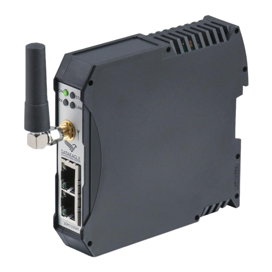
Chapter 3 – Structure 3.2. Radio module The radio module transmits the signals via radio and is avail- able in two radio technologies. Type Radio Technology Ethernet Profinet-Devices Safety Nodes Radio-Slaves 4710 2,4 GHz BT / 100mW 10/ 100MBit max. 4 max. - Page 12 Chapter 3 – Structure The illustration shows all connections of the radio module. Status LEDs connection (configuration) Antenna con- nection Power supply +24V,GND,PE Ethernet connection Relay output (Switch) (radio control) The table shows the significance of the LEDs at the radio module: Name Col-...
-
Page 13: Installation Of New Devices
Chapter 4 – Installation of new devices 4. Installation of new devices Please be certain to read the guidelines in chapter 7 „Tips and Tricks – improvement of the electromagnetic compatibility (EMC)“. Observe these guidelines during the complete installation procedure. Thereby you avoid electromagnetic interferences and you improve the data transmission quality. -
Page 14: Install Unit On Top-Hat Rail
Chapter 4 – Installation of new devices 4.2. Install unit on top-hat rail Place the unit diagonally from above on the top-hat rail. Nose above the top-hat rail Press the unit strongly downwards. Foot catch snaps in Installation and commissioning DATAEAGLE 4XXX Compact... -
Page 15: Install Antenna Cable
Chapter 4 – Installation of new devices 4.3. Install antenna cable Connect the antenna cable to the antenna connection of the radio module. CAUTION The radio module may be damaged if the antenna cable is fastened too tight. Connect the antenna cable only hand-tight. ... -
Page 16: Connect Ethernet Plug
Chapter 4 – Installation of new devices 4.4. Connect Ethernet plug Connect the Ethernet plug. 4.5. Connect power supply Connect the power supply according to the diagram shown below. Either the 9-33 V supply of the control cabinet can be used. ... - Page 17 Chapter 4 – Installation of new devices CAUTION PE has to be connected with control cabinet round! If the PE is not connected the noise filter cannot filter interfer- ences on 9-33V DC power supply line. These may cause malfunctions, errors or the destruction of the device. Supply source needs to be in compliance with SELV and LPS output according UL/IEC 60950-1 or ES1 and PS2 output according UL/IEC 62368-1.
-
Page 18: Extension And Exchange
Chapter 5 – Extension and exchange 5. Extension and exchange If the system is extended or if modules are exchanged the modules must be newly configured after installation. There- fore the USB drivers and the software Dataeagle Wizard must be installed on your PC and the radio module has to be connected to the PC. -
Page 19: Microsoft Internet Explorer
Chapter 5 – Extension and exchange 5.1.3. Microsoft Internet Explorer To ensure a safe function it is important that you define Mi- crosoft Windows Explorer as standard browser before you in- sert the CD ROM into the drive. Only when Microsoft Internet Explorer is not the stand- ard browser: ... -
Page 20: Install Usb Drivers
USB drivers. Insert the CD in your CD-ROM drive. The browser shows the available documents and down- loads for all Schildknecht products. Scroll until you find your product, e.g. DE Compact 4712. ... - Page 21 Chapter 5 – Extension and exchange The available files/applications are shown. Start the application „CDM v2.12.00 WHQL Certified“ (Double click). The following message appears: Click on „Alle extrahieren“. Mark the application „CDM v2.12.00 WHQL Certified“ with the right mouse key.
- Page 22 Chapter 5 – Extension and exchange Click on „Extract“. The installation wizard is started: Click on „Weiter“. The license agreement is shown. Installation and commissioning DATAEAGLE 4XXX Compact...
- Page 23 Chapter 5 – Extension and exchange Click on „Weiter“. The USB drivers are loaded. Click on „Fertig stellen“. The USB drivers are now installed. Use the "Auto-detect COM-Port" function of the Dataeagle Wizard to establish a USB connection to the radio module. Installation and commissioning DATAEAGLE 4XXX Compact...
-
Page 24: Install Dataeagle Wizard
Load Dataeagle Wizard from the CD: Select your product in the browser, e.g. DE XTREME 4713. Click on Load Dataeagle Wizard from the homepage: http://www.schildknecht.ag/download/konfiguration-und-diagnosesoftware Start download. Open an unpack file. Installation and commissioning DATAEAGLE 4XXX Compact... - Page 25 Chapter 5 – Extension and exchange Start Setup The installation program is started. Click on „Installieren“. The program is loaded and opened: Installation and commissioning DATAEAGLE 4XXX Compact...
-
Page 26: Extension
Chapter 5 – Extension and exchange 5.2. Extension There are two ways to extend the radio system: An additional Profinet Slave / Safety Node (SN) is con- nected to an existing Radio Slave. An additional Radio Slave is integrated into the radio system. -
Page 27: Start Dataeagle Wizard
Chapter 5 – Extension and exchange 4.2. to 4.5. 5.2.3. Start Dataeagle Wizard Start the Dataeagle Wizard. The Dataeagle Wizard is stored in the folder „Schildknecht AG“ during installation. The start screen appears: Installation and commissioning DATAEAGLE 4XXX Compact 5-10... -
Page 28: Configure Radio Master
Chapter 5 – Extension and exchange 5.2.4. Configure Radio Master Connect the Radio Master with an USB cable to the Click on „Connect“. Installation and commissioning DATAEAGLE 4XXX Compact 5-11... - Page 29 Chapter 5 – Extension and exchange After the radio module is detected the following message ap- pears: Acknowledge with „OK“. The Radio Master is shown, e.g. Dataeagle 4713 Master. Installation and commissioning DATAEAGLE 4XXX Compact 5-12...
- Page 30 Chapter 5 – Extension and exchange Display Double-click on the device name, then double-click on addresses „Radio“. The radio module addresses are shown: In this example the radio system consists of one Radio Mas- ter with address 01 and two Radio Slaves with the addresses 02 and 03.
- Page 31 Chapter 5 – Extension and exchange Add new Click on „Add“. address Enter the new address, e.g. 4 and click „OK“. The new Radio Slave address is shown Installation and commissioning DATAEAGLE 4XXX Compact 5-14...
- Page 32 Chapter 5 – Extension and exchange Display Channel/ Click once on „869 MHz“ (for Dataeagle 43XX) ) or Bluetooth MAC once on „Bluetooth“ (for Dataeagle 47XX). Address The set channel or the Bluetooth MAC address is shown: Note the channel, e.g. Channel 1 or the Bluetooth MAC address, e.g.
-
Page 33: Configure Radio Slave
Chapter 5 – Extension and exchange 5.2.5. Configure Radio Slave Connect the Radio Slave with an USB cable to the PC. Click on „Connect“. Acknowledge with „OK“. The Radio Slave is shown, e.g. Dataeagle 4713 Slave. Installation and commissioning DATAEAGLE 4XXX Compact 5-16... - Page 34 Chapter 5 – Extension and exchange Enter addresses Double-click on the device name and then double-click on „Radio“. The radio module addresses are shown: Enter the correct addresses. The Radio Master has the station address 01 and partner ad- dress 04 was assigned to the new radio module.
- Page 35 Kapitel 5 - Erweiterung und Austausch Enter Channel/ Click once on „869 MHz“ (for Dataeagle DEC 43XX) or Bluetooth MAC once on „Bluetooth“ (for Dataeagle 47XX). Address The channel or the Bluetooth MAC address is shown: Enter the channel or the Bluetooth MAC address you have noted before.
-
Page 36: Exchange
Chapter 5 – Extension and exchange 5.3. Exchange The exchange of a module is carried out according to the procedure shown below: Remove the wiring Remove the old module Install unit on top-hat rail Connect antenna cable ... -
Page 37: Remove Wiring
Chapter 5 – Extension and exchange 5.3.1. Remove wiring Remove the Ethernet plug and the antenna cable. Remove the power supply (best with a small screw driver). 5.3.2. Remove old module Pull the foot catch downwards and tilt the module up- wards. -
Page 38: Start Dataeagle Wizard
No configuration with the Dataeagle Wizard is necessary when an I/O module has been exchanged. Start the Dataeagle Wizard. The Dataeagle Wizard is stored in the folder „Schildknecht AG“ during installation. The start screen appears: Installation and commissioning DATAEAGLE 4XXX Compact... -
Page 39: Procedure For Exchanging Radio Modules
Chapter 5 – Extension and exchange 5.3.5. Procedure for exchanging radio modules The further procedure depends on the type of the radio mod- ule (Dataeagle 43XX with 869 MHz or Dataeagle 47XX Blue- tooth) and whether a Radio Master or a Radio Slave have been exchanged. -
Page 40: Example 1: Exchange Of A Radio Slave
Chapter 5 – Extension and exchange 5.3.6. Example 1: Exchange of a Radio Slave Overview Connect Radio Master to Wizard Read off Radio Master address Determine address of the exchanged Radio Slave Connect Radio Slave to Wizard ... - Page 41 Chapter 5 – Extension and exchange Click on „Connect“. After the radio module is detected the following message ap- pears: Acknowledge with „OK“. The Radio Master is shown, e.g. Dataeagle 4713 Master. Installation and commissioning DATAEAGLE 4XXX Compact 5-24...
- Page 42 Chapter 5 – Extension and exchange Display address Double-click on the device name and then double-click on „Radio“. The radio module addresses are shown: In this example the radio system consists of one Radio Mas- ter with address 01 and three Radio Slaves with the ad- dresses 02, 03 and 04.
- Page 43 Chapter 5 – Extension and exchange Display channel/ Click once on „869 MHz“ (for Dataeagle 43XX) or on Bluetooth MAC „Bluetooth“ (for Dataeagle 47XX). address The set channel or the Bluetooth MAC address is shown: Note the channel, e.g. Channel 1 or the Bluetooth MAC address, e.g.
- Page 44 Chapter 5 – Extension and exchange Configure Radio Connect the newly installed Radio Slave with an USB Slave cable to the PC. Click on „Connect“. Acknowledge with „OK“. The Radio Slave is shown, e.g. Dataeagle 4713 Slave. Installation and commissioning DATAEAGLE 4XXX Compact 5-27...
- Page 45 Chapter 5 – Extension and exchange Enter addresses Double-click on the device name and then double-click on „Radio“. The radio module addresses are shown: Enter the correct addresses. The Radio Master has the station address 01 and the ex- changed radio module has the partner address 03.
- Page 46 Chapter 5 – Extension and exchange Enter channel/ Click once on „869 MHz“ (for Dataeagle 43XX) or Bluetooth MAC once on „Bluetooth“ (for Dataeagle 47XX). address The channel or the Bluetooth MAC address is shown: Enter the channel or the Bluetooth MAC address you have noted before.
-
Page 47: Example 2: Exchange Of A Radio Master
Chapter 5 – Extension and exchange 5.3.7. Example 2: Exchange of a radio master Overview Connect Radio Slave to Wizard Read off Radio Master and Radio Slave addresses Exchange of Dataeagle Exchange of Dataeagle 43XX 47XX (869 MHz) (Bluetooth) Read off channel Connect Radio Master to... - Page 48 Chapter 5 – Extension and exchange Connect Radio Slave to Wizard Connect the Radio Slave with the USB cable to the PC. Click on „Connect“. Installation and commissioning DATAEAGLE 4XXX Compact 5-31...
- Page 49 Chapter 5 – Extension and exchange After the radio module is detected the following message ap- pears: Acknowledge with „OK“. The Radio Slave is shown, e.g. Dataeagle 4713 Slave. Installation and commissioning DATAEAGLE 4XXX Compact 5-32...
- Page 50 Chapter 5 – Extension and exchange Display Double-click on the device name and then double-click addresses on „Radio“. The radio module addresses are shown, e.g.: The Radio Slave has station address 02. The partner ad- dress is 01 = station of the Radio Masters. ...
- Page 51 Chapter 5 – Extension and exchange Procedure for exchanging a Radio Master type Dataeagle 43XX with 869 MHz Display channel Click once on „869 MHz“ The set channel is shown: Note the channel, e.g. Channel 1. Installation and commissioning DATAEAGLE 4XXX Compact 5-34...
- Page 52 Chapter 5 – Extension and exchange Configure Radio Connect the newly installed Radio Master with an USB Master cable to the PC. Click on „Connect“. Acknowledge with „OK“. The Radio Master is shown, e.g. Dataeagle 4323 Master. Installation and commissioning DATAEAGLE 4XXX Compact 5-35...
- Page 53 Chapter 5 – Extension and exchange Enter addresses Double-click on the device name and then double-click on „Radio“. The radio module addresses as pre-set in the factory are shown: Enter now the correct addresses. In this example the radio system consists of one Radio Mas- ter with address 01 and three Radio Slaves with the ad- dresses 02, 03 and 04.
- Page 54 Installation and commissioning DATAEAGLE 4XXX Compact 5-37...
- Page 55 Chapter 5 – Extension and exchange Add partner address Click on „Add“. Enter the first address, e.g. 04 and click „OK“. Repeat the entry for the other addresses. Station and all partner addresses are displayed Installation and commissioning DATAEAGLE 4XXX Compact 5-38...
- Page 56 Chapter 5 – Extension and exchange Enter channel Click once on „869 MHz“ The channel as pre-set in the factory is shown: Enter the channel you have noted before. Click on „Save Parameter“. The new configuration of the Radio Slave is saved. ...
- Page 57 Chapter 5 – Extension and exchange Procedure for exchanging a Radio Master type Dataeagle 47XX with Bluetooth Configure Radio Connect the newly installed Radio Master with an USB Master cable to the PC. Click on „Connect“. Acknowledge with „OK“. The Radio Master is shown, e.g.
- Page 58 Chapter 5 – Extension and exchange Enter addresses Double-click on the device name and then double-click on „Radio“. The radio module addresses as pre-set in the factory are shown: Enter the correct addresses. In this example the radio system consists of one Radio Mas- ter with address 01 and three Radio Slaves with the ad- dresses 02, 03 and 04.
- Page 59 Chapter 5 – Extension and exchange Add partner address Click on „Add“. Enter the first address, e.g. 04 and click „OK“. Repeat the entry for the other addresses. Station and all partner addresses are displayed Installation and commissioning DATAEAGLE 4XXX Compact 5-42...
- Page 60 Chapter 5 – Extension and exchange Display Click once on „Bluetooth“ Bluetooth/MAC address The Bluetooth MAC Address of the newly installed Radio Master is shown: Note the Bluetooth MAC address, e.g. 0012f30e69d5 Click on „Save Parameter“. The new configuration of the Radio Slave is saved.
- Page 61 Chapter 5 – Extension and exchange Configure Radio Connect one of the Radio Slave with the USB cable to Slaves the PC. Click on „Connect“ Acknowledge with „OK“. The Radio Slave is shown, e.g. Dataeagle 4713 Slave. ...
-
Page 62: Increasing The System Availability (Profinet Only)
Chapter 6 – Filter time 6. Increasing the system availability (Profinet only) 6.1. Function The filter time is used to suppress short radio interferences. This function is only active for cyclical data transmission like Profinet. If a radio slave cannot be accessed due to an interference, a bus error is indicated to the Profinet controller only after the filter time has been elapsed. - Page 63 Chapter 6 – Filter time Click on „Connect“ After the radio module has been found the following mes- sage appears: Acknowledge with „OK“. Installation and commissioning DATAEAGLE 4XXX Compact...
- Page 64 Chapter 6 – Filter time The Radio Master is shown, e.g. Dataeagle 4713 Master. Double-click on the device name, then double-click on „Interface“, then once on „DP Parameter“. Adjustment range for the filter time: 0,1s to 25,5s Installation and commissioning DATAEAGLE 4XXX Compact...
- Page 65 Chapter 6 – Filter time Click on „Save Parameter“. The new configuration is saved. Click on „Disconnect“. From interface version DE4x10 (see type label) no adjust- ments at the radio slave are required (the filter time is trans- ferred automatically from the radio master).
-
Page 66: Typical Values For The Filter Time
Chapter 6 – Filter time 6.3. Typical values for the filter time 6.3.1. Default The factory setting of the filter time is 2 sec. 6.3.2. Recommendation for operation Typical filter delay times in operation should be between 500 ms and 2 s. The filter time should be increased under the following condi- tions: ... -
Page 67: Dismantling And Disposal
Chapter 7 – Dismantling and disposal 7. Dismantling and disposal Remove the Ethernet plug and the antenna cable. Remove the power supply (best with a small screw driver) Pull the foot catch downwards and tilt the module up- wards. -
Page 68: Tips And Tricks
Chapter 8 – Tips and Tricks 8. Tips and Tricks 8.1. Improving the EMC safety 8.1.1. Introduction The wireless data systems DATAEAGLE are electronic devices which are built according to the latest state of technology. The ruggedly mechanical structure as well as the construction of the electronic components is designed for industrial applications. - Page 69 Chapter 8 – Tips and Tricks Shielding Use always screened cables for the interface cable and the supply cable. Thereby you reduce the interference probability by a ratio of 100 compared to unshielded cables and even up to a ratio of 1000 if you also avoid loops. The density of the shield netting should be at least 85%.
- Page 70 Chapter 8 – Tips and Tricks Connections to EMC earth Design all connections with EMC earth as short as possible and as extensive as possible. Pay attention that all metallic housings have good contact to the galvanized mounting surface. Housing for sources of Pay attention that all electronic or electric parts which should interference...
- Page 71 Chapter 8 – Tips and Tricks In highly disturbed environmental conditions, which may occur for example in industry buildings with induction furnaces we recommend a PE free installation (see illustration). The galvanized mounting plate cannot be grounded due to the high voltage drop of the different grounding points within the building.
-
Page 72: Guidelines For Optimized Installation Of Antennas
Chapter 8 – Tips and Tricks 8.2. Guidelines for optimized installation of an- tennas Orientation All antennas should have the same orientation, e.g. vertical. So nicht! Distance and free radiation Keep sufficient distance to metal parts and walls. Keep maximum distance to motors and frequency converters. - Page 73 Chapter 8 – Tips and Tricks Line of sight The best data transmission quality will be achieved when the antennas are installed in a line of sight at an elevated and free location. Out-off the Install antennas outside of the control cabinet. control cabinet Electromagnetic radiation.
-
Page 74: Advices For Troubleshooting
Chapter 8 – Tips and Tricks 8.3. Advices for troubleshooting Settings Check the setting of all modems. Pay attention to correct settings of channel, station and partner address. Distance Check the distance towards the partner station. Select first a distance of a few meters and increase the distance step by step up to the intended distance. -
Page 75: Technical Specifications
Chapter 9 – Technical specifications 9. Technical specifications DATAEAGLE Compact 4712 DATAEAGLE Compact 4713 General Power supply Input Voltage 24V DC 24V DC Rated Input Voltage Range 9-33V DC 9-33V DC Connection power supply Screw terminal block Screw terminal block Power consumption Fastening DIN rail mounting... - Page 76 Chapter 9 – Technical specifications DATAEAGLE Compact 4715 DATAEAGLE Compact 4710 General Power supply Input Voltage 24V DC 24V DC Rated Input Voltage Range 9-33V DC 9-33V DC Connection power supply Screw terminal block Screw terminal block Power consumption Fastening DIN rail mounting DIN rail mounting Protection...
- Page 77 Chapter 9 – Technical specifications DATAEAGLE Compact 4333 General Power supply Input Voltage 24V DC Rated Input Voltage 9-33V DC Connection power supply Screw terminal block Power consumption Fastening DIN rail mounting Protection IP20 Temperature range -20°C … 60°C Conformity Weight 160 g Width...
Need help?
Do you have a question about the DATAEAGLE COMPACT 4 Series and is the answer not in the manual?
Questions and answers