Advertisement
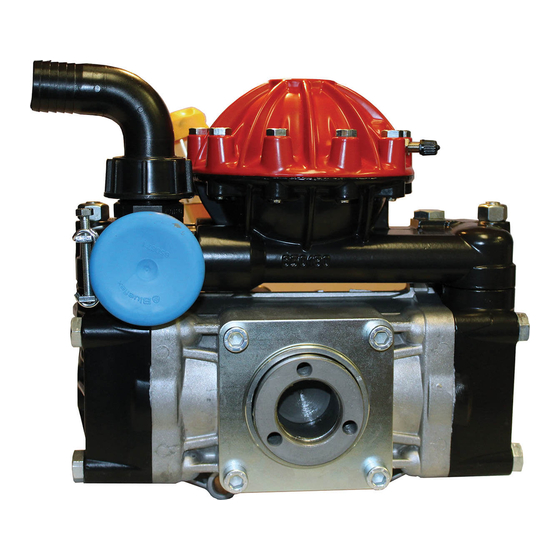
140° F - Max Water Temp
1-1/4" - Suction
1/2" NPT - Outlet
MODEL
AR50-SP
AR50-SP/A1
AR50-GR1-GCI
GCI - Pump with a mounted control unit .
d
K
iAPHRAgm
iTS
m
d
odeL
eScRiPTion
AR43293
BlueFlex
AR43291
Desmopan
AR43290
Buna
INSTRUCTION MANUAL
MAXGPM
MAX L/MIN
14.8
14.8
14.8
V
K
ALVe
iTS
m
d
odeL
eScRiPTion
AR1920
Valves
MAX PSI
65.8
580
65.8
580
65.8
580
o-R
K
ing
iTS
m
d
odeL
eScRiPTion
AR1919
O-Rings
AR 50
MAX BAR
HP POWER
40
5.2
40
5.2
40
5.2
o
iL
m
d
odeL
AR64532D
Oil
AR64532D-C Case (6)Oil
WEIGHT
LBS.
39.3
39.3
50.0
eScRiPTion
Advertisement
Table of Contents

Related Manuals for Annovi Reverberi AR 50


Summary of Contents for Annovi Reverberi AR 50
- Page 1 AR 50 140° F - Max Water Temp 1-1/4” - Suction 1/2” NPT - Outlet INSTRUCTION MANUAL WEIGHT MODEL MAXGPM MAX L/MIN MAX PSI MAX BAR HP POWER LBS. AR50-SP 14.8 65.8 39.3 AR50-SP/A1 14.8 65.8 39.3 65.8 AR50-GR1-GCI 14.8 50.0...
-
Page 2: Drive Options
Drive Options Gearbox Kit AR1639: 1” 8-18 HP Gas Engines Gearbox Kit AR1636: 3/4” for 5-6HP Gas Engine Gearbox for four stroke engines Gearbox for four stroke engines with SAE J609a flange with SAE J609a flange Ø 1" Ø 1" Shaft Kit AR43394: 1 3/8”... -
Page 3: Important Safety Information
IMPORTANT SAFETY INFORMATION Intended uses The pump is designed and constructed for incorporation in plants and machinery (spraying machines for the protective treatment of agricultural crops and garden plants). All other uses constitute misuse unless ap- proved by the manufacturer's technical service The pump must be used in a manner appropriate to its technical data (see “Technical Data”), and must not be modified or improperly used. -
Page 4: Control Unit Operation
Control Unit GI40 & GIC40 GI40 and GIC40 Control Units: Control units are available for easy flow and pressure control of your sprayer system. These units include a manual dump valve and adjustable pressure relief valve to control pressure, a liquid-filled pressure gauge to monitor pressure, and shut-off valves to control flow. - Page 5 Installation • The crankshaft may turn in either direction. • The water connection with the pump must be made using hoses of suitable diameter, in all case no less than that of the pump fittings, securing them to the fittings using good quality clamps. The intake hose must be coil-reinforced to prevent restrictions.
-
Page 6: Installation Instructions
INSTALLATION INSTRUCTIONS Installation diagram (guideline) The following is a simplified illustration of the typical installation layout and is purely guideline. Control Unit by-pass Tank Agitation plugged strainer or too small a strainer Control Unit Intake filter Pump long inlet hose or too small of hose Delivery line filter... - Page 7 INSTALLATION INSTRUCTIONS General guidelines on water supply connection To operate correctly, the diaphragm pump must draw in liquids from containers at atmospheric pressure. Do not supply the pump with pressurised liquids. For continuous duty, the pump should not draw in water by gravity from containers with liquid level at heights above 3 m.
- Page 8 Safety recommendations for handling and lifting Before starting the operations, organise the intended working area so that the materials can be lifted and handled in safety. Unloading, loading, handling and lifting operations must be carried out by skilled, authorised, specifi cally trained staff.
- Page 9 Safety recommendations for use Before start-up, the operator must perform the necessary safety checks. In the event of leaks from the pressurized pipes, stop the pump at once and fix the leak. Do not operate the pump above the limits set by the manufacturer to increase its performance. Preliminary checks If the pump has a pressure accumulator, check its level of inflation, see "Checking the inflation pressure".
- Page 10 Safety recommendations for maintenance Before doing any maintenance work, depressurise the water system and isolate the pump from all en- ergy sources. When the jobs are done, before restarting the pump, check that no tools, rags or other materials have been left close to moving parts or in hazardous zones.
-
Page 11: Maintenance Instructions
MAINTENANCE INSTRUCTIONS Table of lubricants The pump is delivered complete with high-performance 30 weight, non-detergent oil suitable for the intended ambient conditions (see "Environmental operating limits"). Inspecting the pump mounting Check that the pump's fixing screws have not become loose. If necessary, tighten them with the driving torque stated in the installation design. - Page 12 MAINTENANCE INSTRUCTIONS Checking the inflation pressure If the pump has a pressure accumulator, check its level of inflation, with the pump shutoff using an air chuck fitted with a pressure gauge. The ac cumulator is inflated by the manufacturer for use of the pump at its maximum pressure.
- Page 13 Pump Storage It is important to comply with the recommendations for storage in the operator's manual of the machine into which the pump is incorporated. For the pump itself, at the end of pumping operations it is essential to flush out the internal circuit by pump ing clean water.
-
Page 14: Troubleshooting
TROUBLESHOOTING The information provided is intended to provide guidance how to deal with malfunctions which may occur during use. Some of these procedures may be carried out by skilled staff, while others have to be performed at specialised service centres since they require the use of specific equipment as well as detailed knowledge of repair opera tions. - Page 15 TROUBLESHOOTING Remedy Problem Cause Oil seal on pump Replace the worn oil seal. shaft worn. Oil on pump body or base. Oil pressure inside pump too high. Restore correct oil level in tank. Pump using too much oil (oil flowing from delivery port) or oil Stop the pump at once.
- Page 16 A.R. NORTH AMERICA A.R. NORTH AMERICA AR 50 41 42 46 - 1 46 - 2 46 - 3 46 - 4 651670 available 650670 available 650660 no longer available Obsolete Inlet Pulsation Dampener 46 - 5 46 - 6...
- Page 17 SP/A1 GR3/4-GCI GR1-GCI AR 50 AR50 31736 31737 33132 31739 Code Description Note Code Description Note 650011 Pump body 650150 Manifold 650102 Head 450120 Fitting 1” G - 1”1/4 G M-M 320130 Nut T T 445* 390290 O-ring Ø 29x3...
- Page 18 A.R. NORTH AMERICA A.R. NORTH AMERICA GI 40 / GIC40 AR 503 - AR 713 - AR 813 102 - 2 102 - 6 Code Description Note Code Description Note 620220 Relief valve body 1150580 Hose barb Ø 13 130171 Plug 3/8”...
- Page 19 Remote control Remote control Pos. Pos. Pos. Pos. Pos. Pos. For AR 30 - AR 50 - AR 303 - AR 403 For AR 30 - AR 50 - AR 303 - AR 403 For AR 503 2021 AR North America...
- Page 20 A.R. NORTH AMERICA A.R. NORTH AMERICA A.R. NORTH AMERICA A.R. NORTH AMERICA A.R. NORTH AMERICA A.R. NORTH AMERICA A.R. NORTH AMERICA A.R. NORTH AMERICA A.R. NORTH AMERICA A.R. NORTH AMERICA A.R. NORTH AMERICA A.R. NORTH AMERICA A.R. NORTH AMERICA A.R. NORTH AMERICA A.R.
- Page 21 4 See T220* 21 1320940 Flange 961770 Spacer 4 See 650990 Key 620950 Gasket 650270 Gasket 1 For AR 50 160671 Bolt TCEI M10x25 3 T180* Type Suggested Oil 90 W Gear Lube For gas engine with 1” shaft, flange SAE J609a...
- Page 22 A.R. NORTH AMERICA A.R. NORTH AMERICA AR 1666 : Gear Reduction Per - For: AR 30 - AR 303 - AR 403 Use of engine : B&S Vanguard 6.5 Kohler SH 265 Kohler SH 270 Honda GX 120 Honda GX 160 Honda GP 160 Honda GP 200 Axo AMG 120...
- Page 23 A.R. NORTH AMERICA A.R. NORTH AMERICA AR 33261 : Gear Reduction Per - For: AR 50 - AR503 - AR713 - AR813 - AR1064 Use of engine : B&S Vanguard 10 B&S Vanguard 18 Kohler SH 265 Kohler SH 270...
Need help?
Do you have a question about the AR 50 and is the answer not in the manual?
Questions and answers