Advertisement
Quick Links
Flowmatic
®
With Solenoid, Battery Powered
PRODUCT CODE:
- TZ-IQWAVEB
TECHNICAL DATA
Inlet
Outlet
Headwork
Battery (VDC)
Solenoid
Finish
NOTE: Galvin Specialised continually strive to improve their products. Specifications may change without notice.
SENSOR DETAILS
•
Hardware
•
Software
•
Input Voltage
•
Cable length
•
Sensor function
•
Preset line purge feature interval:
•
Preset continuous run:
•
Sensor range:
TOOLS REQUIRED
−
Power drill
−
Spanner or adjustable crescent
−
Screw driver
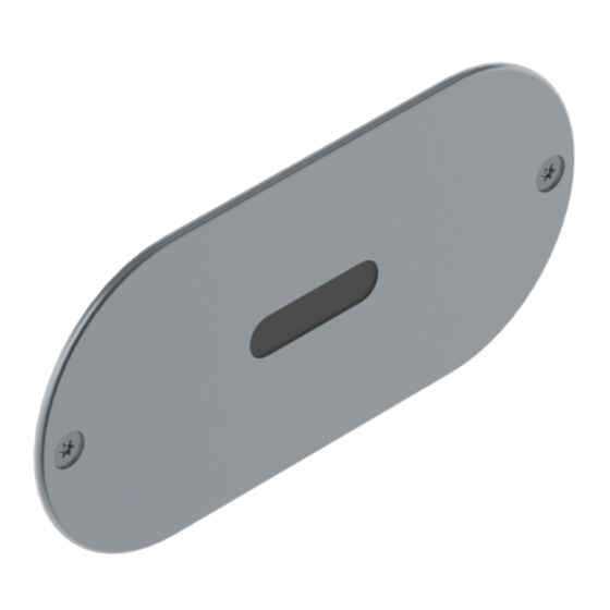
Wave On Activated Concealed Sensor
Input Voltage
Power Consumption
Cable length
Pressure Range (kPa)
Temperature (°C)
Version 1, 25
½" BSP – Female
½" BSP - Male
Solenoid
6
6.75V DC
-
3.2m
Min
50
Max
500
Min
5
Max
80
SS Faceplate
Varox 4.2.2
IQ7VARIR2V 7.15-0256, release 15.5.2015
6.75V DC – 0.5A
3.2m
Standard washbasin (with proximity sensor)
12 hours after last flush, water flow duration 3 min
5 min
Sensor1 and Sensor2 custom made steps
th
March 2020 Page 1 of 6
Advertisement

Related Manuals for Galvin Engineering Flowmatic TZ-IQWAVEB


Summary of Contents for Galvin Engineering Flowmatic TZ-IQWAVEB
- Page 1 Version 1, 25 March 2020 Page 1 of 6 Flowmatic Wave On Activated Concealed Sensor ® With Solenoid, Battery Powered PRODUCT CODE: - TZ-IQWAVEB TECHNICAL DATA ½” BSP – Female Inlet ½” BSP - Male Outlet Headwork Solenoid Battery (VDC) Input Voltage 6.75V DC Power Consumption...
- Page 2 Version 2, 8 April 2020, 2 of 6 Version 1, 25 March 2020 Page 2 of 6 DIMENSIONS − A cavity must be supplied to fit sensor on the back of faceplate as shown, minimum 20mm deep. − Drill 2 x mounting 6.0x30 deep holes, location as shown. Note: See below for a typical installation of the sensor position from basin.
-
Page 3: Installation
Version 2, 8 April 2020, 3 of 6 Version 1, 25 March 2020 Page 3 of 6 INSTALLATION INSTALLATION COMPLIANCE: Galvin Specialised products must be installed in accordance with these installation instructions and in accordance with AS/NZS 3500, the PCA and your local regulatory requirements. Water and/or electrical supply conditions must also comply to the applicable national and/or state standards. - Page 4 Version 2, 8 April 2020, 4 of 6 Version 1, 25 March 2020 Page 4 of 6 SENSOR SETTING INSTRUCTIONS Touch function Hand/object within sensor area Water flows LED flashes Green Signs Water flow stops LED flashes Red symbols H –...
-
Page 5: Troubleshooting
Version 2, 8 April 2020, 5 of 6 Version 1, 25 March 2020 Page 5 of 6 app. 2 sec. till Extended function mode is active Touch max. 5 sec., water flows minimum 3 + after releasing, number of (1x- sec. -
Page 6: Warranty
March 2020 Page 6 of 6 WARRANTY The warranty set forth herein is given expressly and is the only warranty given by the Galvin Engineering Pty Ltd. With respect to the product, Galvin Engineering Pty Ltd makes no other warranties, express or implied.
Need help?
Do you have a question about the Flowmatic TZ-IQWAVEB and is the answer not in the manual?
Questions and answers