Table of Contents
Advertisement
Advertisement
Table of Contents

Related Manuals for twin busch TW 115


Summary of Contents for twin busch TW 115
- Page 2 TWIN BUSCH GmbH Printing errors, mistakes and technical changes reserved ©by TwinBusch Germany...
- Page 3 TWIN BUSCH GmbH INDEX 1. Important note 1.1 Important note 1.2 Specialist 1.3 safety instructions 2. Overview of the wheel alignment device 2.1 general descriptions 2.2 Function 2.3 Specification 2.4 Requirements for the environment 8-12 3. Components of the wheel alignment 3.1 Overview...
- Page 4 TWIN BUSCH GmbH 5.5.3 King pin measuring and set up 5.5. Rear axle measuring and set up 5.5.5 Front axle measuring and set up 5.5.5.1 Set up with a Lifter 5.5.5.2 Toe Curve Change Measurement and set up 5.5.6 Extension Measurement 5.5.7 Steering angle measuring...
-
Page 5: Important Safety Instructions
TWIN BUSCH GmbH Important safety instructions 1.1 Important note Read this manual before using the wheel aligner. 1.2 Professionals 1.2.1 Only trained personnel should operate the wheel alignment. 1.2.2 Electrical connections must be made by an electrician. 1.2.3 Uninvolved persons are not allowed in the vicinity of the wheel alignment. - Page 6 TWIN BUSCH GmbH 2. Overview about the wheel aligner 2.1 General The wheel aligner was designed to measure the axle geometry and compare it with the default values of the vehicle manufacturers. It also gives the user instructions on how to make appropriate adjustments for best steer ability and lowest tire wear.
-
Page 7: Specification
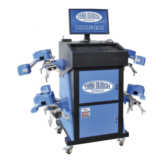
TWIN BUSCH GmbH 2.3 Specification description accuracy measuring range Total toe ±1,2′(±0.02º) ±4º Individual toe ±0,6′(±0.01º) ±2º Camber ±1,8′(±0.03º) ±4º ±6′(±0.1º) Castor ±18º ±6′(±0.1º) SAI / KPI ±18º Setback ±1,8′(±0.03º) ±2º Thrust angle ±2º ±1,8′(±0.03º) NOTE: The measuring accuracy refers to measured values within the measuring range. - Page 8 TWIN BUSCH GmbH 3. The components of the wheel alignment 3.1 Overview The wheel aligner consists essentially of the control panel, the measuring heads, the wheel clamps, the steering wheel holder and the brake pedal pusher etc. 3.2 Operation panel The control panel of the wheel aligner mainly consists of the housing (with recordings for the wheel clamps, main switch, power line, power supply and charging cable), computer and Bluetooth data transfer.
- Page 9 TWIN BUSCH GmbH 3.6 Wheel clamp The wheel aligner has four wheel clamps. Turn the dial so that the distance is large enough to put the clamp on the rim if necessary, insert the pins in reverse and / or into other insertion holes. Then attach the pins first to the rim flange and then to the top of the rim flange.
- Page 10 TWIN BUSCH GmbH 3.7 Steering holder The wheel aligner has a steering wheel holder as shown in the following picture. The steering wheel holder is used to fix the steering wheel against rotation during measuring operations 3.8 Brake holder The wheel aligner has a brake pedal pusher as shown in the picture below.
-
Page 11: Measuring Head
TWIN BUSCH GmbH 3.10 Measuring head The wheel aligner is equipped with four measuring heads, which are mounted on the corresponding wheel clamps. Before attaching the measuring heads, first attach the wheel clamps to the wheels, then insert the axle pin of the corresponding measuring head into the hole of the central carrier. -
Page 12: Measuring Display
TWIN BUSCH GmbH Display: run out compensation display After calling the rim override function, the display A flashes after the first press of the button, display B flashes after the second press of the button, displays A and B go out, the third time the button is pressed. -
Page 13: Set Up And Connect
TWIN BUSCH GmbH 4. Set up and connect 4.1 Set up the device • Place the control panel in a suitable place, with sufficient space for the equipment. Manual, packing list, etc., keep these documents well. • Unpack the monitor, place the supplied material, set it up and connect it. - Page 14 TWIN BUSCH GmbH 5. Basic work steps with the wheel alignment device The basic steps with the wheel aligner are the following: Vehicle information procure → road test → Carry out testing prior test (each chassis part and tire wear carefully check) →...
- Page 15 TWIN BUSCH GmbH 5.2 application interface The display shows the application interface. Info-button shows information about the wheel etc. Quick measurement button provides a working surface for quick measurement in which toe-in and Camber the front and rear wheels are simultaneously measured and displayed.
- Page 16 TWIN BUSCH GmbH 5.3 (F5) System settings If you click on the button (F5), System, the screen shows a user interface as shown in the following picture: Workshop info, for the input of workshop data, such as name, address, telephone and fax etc.
- Page 17 TWIN BUSCH GmbH 5.3.1 (F2) Workshop information If you click the button (F2) Workshop Info, the screen shows a user interface, as shown in the following picture: It is necessary to create your own workshop information before the first use.
- Page 18 TWIN BUSCH GmbH 5.3.2 (F3) my documents If you click the button (F3) My Documents, the screen shows a user interface, as shown in the following picture: On this page, the user can create self-defined survey data (Button F6 ), or import standard data, as well as modify and delete this data.
- Page 19 TWIN BUSCH GmbH 5.3.3 (F4) Standard data If you click the button (F4) Standard data, the screen shows a user interface, as in the following picture: On the Default Data page, the user can query original vehicle survey data. Printing errors, mistakes and technical changes reserved...
- Page 20 TWIN BUSCH GmbH 5.3.4 (F5) Configuration System If you click the button (F5) configuration system, the screen shows a user interface, as in the following picture: Select Version: here you can choose between the normal and the demo version. If you do a survey, you have to choose the normal version.
- Page 21 TWIN BUSCH GmbH 5.3.5 (F6) Sensor information If you click the button (F6) sensor information, the screen shows a user interface, as shown in the following picture: If the colored dot is on the far left, right, or jump, it indicates that the sensor inside the probe is faulty. This function performs a self-test on the faulty sensor.
- Page 22 TWIN BUSCH GmbH 5.3.6 (F7) Lift settings If you click the button (F7) lift calibration, the screen shows a user interface, as in the following picture: Sometimes the left and right sides of the platforms are not at the same height due to inaccurate mounting.
- Page 23 TWIN BUSCH GmbH 5.4 (F6) Customer management If you click on the button (F6) Customer Management, in the main screen the screen shows a user interface, as in the following picture: Customer information, for customer name, telephone number, address. Measurement log, for the display of number plate, check date and cause of error.
- Page 24 TWIN BUSCH GmbH Printing errors, mistakes and technical changes reserved ©by TwinBusch Germany...
- Page 25 TWIN BUSCH GmbH The necessary customers data can be entered with button F6 , including name, address, telephone number and creation date etc. button F5 (Clear) Customer data or the measurement record. If there are several measurement records under a customer name, all measurement records are automatically deleted when a customer is deleted.
- Page 26 TWIN BUSCH GmbH 5.5 (F4) Measuring Pressing (F4) Measurement opens the main screen of the wheel alignment. The corresponding Press function key or shortcut key to call up the corresponding interface function. 5.5.1 Select a Vehicle If you press the (F4) Measurement key, the vehicle selection automatically opens, as shown in the following figure.
- Page 27 TWIN BUSCH GmbH On the screen you can choose the right manufacturer, vehicle model and year, for example: Audi A6 from 2012 till 2017 With the button F12 you can optionally enter the tire diameter, optionally via the wheel size.
- Page 28 TWIN BUSCH GmbH Depending on the vehicle selected, the system will proceed to two measurement methods: 1 Balancing weight method; for vehicles which must be loaded with predetermined weights for testing The weights must be placed as indicated. This screen also comes when (as in the example, then without values) vehicles do not require any special measurement method.
- Page 29 TWIN BUSCH GmbH 2 Ground clearance method; for vehicles which have to be measured according to the chassis height, the corresponding screen automatically appears. Measure according to the requirements of the screen the height of the specified positions (with measuring tool such as tape measure, etc.) and select the data of the applicable fields.
- Page 30 TWIN BUSCH GmbH 5.5.2 Run out compensation This function serves to reduce the error that can be caused by deformations of wheel and tire. It is recommended to select the function to get a better accuracy of the measurements. Before the rim stroke compensation, remove the brake pedal pusher, block the steering wheel with the steering wheel lock, and lift the vehicle with an axle lift.
- Page 31 TWIN BUSCH GmbH 5.5.3 Caster measurement and adjustment Press the caster measurement button or F4 to call the caster measurement. Then do the work according to the animation and the displayed text. If you do not want to perform a follow-up measurement, you can directly press the function keys after the follow-up measurement to perform the other function.
- Page 32 TWIN BUSCH GmbH Turn the steering wheel to the right according to the on-screen display as soon as the display is in the right green area. Hold the steering wheel until the screen prompting the steering wheel to turn to the left, as shown in the following image: Printing errors, mistakes and technical changes reserved ©by TwinBusch Germany...
- Page 33 TWIN BUSCH GmbH Turn the steering wheel to the left according to the on-screen display as soon as the display is in the middle green range. Hold the steering on the middle point till the measuring is done: Printing errors, mistakes and technical changes reserved...
-
Page 34: Detailed Data Display
TWIN BUSCH GmbH 6. Detailed data display On the Tracking Results screen, press the Detail Data button or Ctrl + F4, the Detailed Information screen displays the Caster, Front and Rear Wheel Survey parameters, as shown in the image below:... - Page 35 TWIN BUSCH GmbH 5.5.4 Rear axle measurement and adjustment Press the rear axle measurement button or F5 to call up the rear axle measurement program. Then perform the work according to the animation and the displayed text. The rear axle measurement and adjustment screen will look like the following picture.
- Page 36 TWIN BUSCH GmbH 5.5.5 Front axle measurement and adjustment Press the front axle measurement or F6 button to call up the front axle measurement and adjustment program. Then do the work according to the animation and the displayed text. The front wheel alignment and adjustment screen looks like the following image.
- Page 37 TWIN BUSCH GmbH Note: While lifting the vehicle with the axle jack, the wheels must always touch the turntables and the turntables must not move on the lift. Otherwise the measurement will be falsified. 5. Check the current values of the toe-in change in position B2 according to the on-screen prompts.
- Page 38 TWIN BUSCH GmbH 5.5.7 Steering angle measurement Press the Steering angle measurement button or F8 to call the Steering angle measurement as shown in the following figure. There are two options on this screen: cornering or maximum steering angle. After selecting the desired function, perform the operations as shown on the screen.
- Page 39 TWIN BUSCH GmbH If a new customer has to be created, press the button. The screen for entering and changing new customers appears. If the field Customer information is selected, You can use the button to create, change or delete further customer information.
-
Page 40: Preliminary Investigations
TWIN BUSCH GmbH 5.6 Quick measuring In the main menu you can use the F3 key to select the program for the quick measurement. This is a quick-action work surface that allows you to simultaneously check and see the camber and lane of front and rear wheels after the vehicle has been selected. -
Page 41: Maintenance
The measuring heads are precision parts, please handle with care. Manipulation may damage the internal components and interfere with normal operation. • Do not disassemble the measuring heads to avoid damage to the component. Twin Busch does not warrant for such errors. 6.3 Printer (not included) •... - Page 42 TWIN BUSCH GmbH 7. Annex 7.1 fundamental terms Center line of the wheels: The contact between the tire and the ground forms a line to which the middle line of the wheels is vertical. A- Centerline of the wheels Vehicle Centerline: The line passing through the center of the front axle and the center of the rear axle.
- Page 43 TWIN BUSCH GmbH 7.2.1.1 Function Reduction of tire wear and rolling resistance. 7.2.1.2 Assessment of the symptoms 7.2.1.2.1 Toe too big. a. big wear on the outside of the tire. For radial tires, the wear pattern is similar to excessive positive camber.
- Page 44 TWIN BUSCH GmbH 7.2.2.1 Function Adjust vehicle load to center of wheels, remove drag and reduce tire wear. 7.2.2.2 Assessment of the symptoms 7.2.2.2.1 Effects of too much positive camber a. Tires wear out only on the outside. b. stronger suspension wear.
- Page 45 TWIN BUSCH GmbH 7.2.4 Caster Caster is the inclination of the kingpin to the front or rear from the vertical. If the slope is to the rear, the caster is positive, he is forward, and the caster is negative. 7.2.4.1 Function The caster angle influences the steering stability and the self-return of the steering.
- Page 46 TWIN BUSCH GmbH 7.2.6 Thrust angle The included angle is the angle between the center line of the wheel and the axes of the fall, usually the geometric sum of camber and SAI. 7.2.7 Toe-out when cornering Turning on cornering is defined as the difference of the steering angle (track difference angle) between the two front wheels turned by 20 °...
- Page 47 TWIN BUSCH GmbH 7.2.8.1 Reasons which cause thrust angle • Driving angle is created when an axis offset is generated. • Rear track is asymmetric. 7.2.8.2 Effects of the driving angle • Tire wear. • Steering wheel misalignment. • Pull.
- Page 48 TWIN BUSCH GmbH My notes: Printing errors, mistakes and technical changes reserved ©by TwinBusch Germany...
- Page 49 TWIN BUSCH GmbH My notes: Printing errors, mistakes and technical changes reserved ©by TwinBusch Germany...
- Page 50 TWIN BUSCH GmbH My notes: Printing errors, mistakes and technical changes reserved ©by TwinBusch Germany...
- Page 51 TWIN BUSCH GmbH Printing errors, mistakes and technical changes reserved ©by TwinBusch Germany...
- Page 52 TWIN BUSCH GmbH Printing errors, mistakes and technical changes reserved ©by TwinBusch Germany...
Need help?
Do you have a question about the TW 115 and is the answer not in the manual?
Questions and answers
Hello, I have a twin busch tw115, could you please send me how to calibrate it?