Table of Contents
Advertisement
Available languages
Available languages
FAILURE TO READ AND FOLLOW ALL INSTRUCTIONS CAREFULLY
BEFORE INSTALLING OR OPERATING THIS CONTROL COULD CAUSE
PERSONAL INJURY AND/OR PROPERTY DAMAGE.
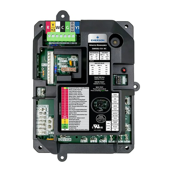
• 50M56U-751 Integrated Furnace Control
• 9-Pin Adapter Harness
• Flip Adapter Harness
50M56U-751 is an aftermarket direct replacement
control kit for Carrier and ICP single stage furnace
products with PSC blower motors.
ELECTRICAL RATINGS:
Input Low Voltage: 24 VAC, 60 Hz
Input Line Voltage: 120 VAC, 60 Hz, 1φ
Max Input Current: 0.45 A @ 24 VAC
Relay Contact Ratings:
Gas Valve: 1.5 A, 0.6 PF @ 24 VAC
Ignitor Relay: 1.2 A @ 120 VAC
Inducer Relay: 2.8 A @ 120 VAC
Circulator Relay: 10 FLA, 25 LRA @ 120 VAC
Humidifier Load: 1.0 A @ 24 or 120 VAC
Electronic Air Cleaner: 1.0 A @ 120 VAC
Flame Current Requirements:
Minimum current to ensure flame detection:
0.25 μA DC*
Maximum current for non-detection: 0.1 μA DC
Maximum allowable leakage resistance: 100 M
ohms
* Measured with a DC ammeter
Flame Establishing Time: 0.8 seconds maximum
Flame Failure Response Time:
2.0 seconds maximum
OPERATING TEMPERATURE RANGE:
-40° to 176°F (-40° to 80°C)
HUMIDITY RANGE:
5 to 95% relative humidity (non-condensing)
50M56U-751 with Black Cover
INSTALLATION INSTRUCTIONS
emerson.com/white-rodgers
Carrier/ICP Integrated Single Stage
120V Hot Surface Ignition Control Kit
• 4 – 1" Sheet Metal Screws
• 3 – 1/2" Sheet Metal Screws
• Installation Instructions
TWINNING: 50M56U-751 can be twinned. The other
control must also be a 50M56U-751 with Black
cover to ensure proper functionality.
SPECIFICATIONS & TIMINGS
AGENCY APPROVALS:
GASES APPROVED:
Natural, Manufactured, Mixed, Liq-
uid Petroleum, and LP Gas Air Mixtures.
Risk of Electric Shock.
Disconnect electric power
to system until installation
is complete. Do not use on
circuit exceeding specified
voltage. Higher voltage will
damage control and could
cause shock or fire hazard.
This control is not intended
for use in locations where
it may come in contact with
water.
May cause flame rollout.
Shut off main gas to
heating
installation is complete.
PARTS INCLUDED
DESCRIPTION
UL USA / Canada
system
until
PART NO. 37-7751001
2031
Advertisement
Table of Contents

Subscribe to Our Youtube Channel
Related Manuals for White Rodgers 50M56U-751


Summary of Contents for White Rodgers 50M56U-751
- Page 1 DESCRIPTION TWINNING: 50M56U-751 can be twinned. The other 50M56U-751 is an aftermarket direct replacement control must also be a 50M56U-751 with Black control kit for Carrier and ICP single stage furnace cover to ensure proper functionality. products with PSC blower motors.
- Page 2 Furnace 9-Pin 11-Pin NOTE: Furnaces previously serviced with Carrier 325878-751, ICM 282A, or White-Rodgers 50M56U-751 kits may have an adapter harness already installed between the factory wiring and the control being replaced. If found, remove the old adapter harness and replace it with the new one provided in the kit.
-
Page 3: Installation
SPARE terminals. Apply wire ties as needed to control, then remove existing control. secure wiring. 3. Mount 50M56U-751 in the unit using one of the 7. Verify Heat ON delay, Constant Fan Speed, Heat three mounting options noted in the Mounting OFF Delay, and Cool OFF Delay settings, as section. - Page 4 5 seconds by placing a jumper between the Y/Y2 and DHUM thermostat inputs. Automatic Configuration 50M56U-751 automatically configures its functional operation to match that of the OEM control being replaced across a variety of Carrier and ICP applications. This automatic configuration feature allows 50M56U-751 to accept various connections (HPS Input, Inducer Ground, or Not Connected) on Pin 3 of the 11 Pin main harness connector.
-
Page 5: Wiring Diagram
GAS VALVE OUT SEC-2 (SEE 11 PIN DETAIL) FAULT RECALL PUSH BUTTON DIPSWITCHES SW1-1 HEAT ON DELAY SW1-2 FAN SPEED TWIN TERMINAL SW1-3&4 HEAT OFF DELAY CONNECT TO ANOTHER 50M56U-751 FLAME CURRENT SENSE 1VDC=1µA NEUTRAL EAC-2 PR-2 HUMIDIFIER 120VAC 120V HUM... -
Page 6: Operation
OFF delay for a fan only demand. Air Conditioner & Heat Pump • Set thermostat to Fan ON for continuous fan. • Systems retrofitted with 50M56U-751 can be paired with either a 1 or 2 stage air conditioner or heat Dehumidification pump. -
Page 7: Troubleshooting
TROUBLESHOOTING Green LED Flash Amber LED Flash Red LED Flash Error / Condition Up to 5 Flash Codes Stored in Memory (Auto-Erased After 14 Days) Limit / Roll-Out Lockout Ignition Lockout - After 3 Retries Ignition Lockout - After 10 Recycles Ignitor Failure - Replace Ignitor Gas Heating Lockout Abnormal Flame Proving Signal... - Page 8 TECHNICAL SUPPORT: 1-888-725-9797 Emerson and White-Rodgers are trademarks of Emerson Electric Co. ©2020 Emerson Electric Co. emerson.com/white-rodgers All rights reserved.
-
Page 9: Directives D'installation
• Directives d’installation DESCRIPTION JUMELAGE : La commande 50M56U-751 peut être jumelée. La commande 50M56U-751 est une trousse de commande de L’autre commande doit également être une 50M56U-751 avec un rechange universelle du marché des pièces de rechange pour les couvercle noir pour assurer le fonctionnement approprié. - Page 10 REMARQUE : Les fournaises précédemment entretenues avec les trousses Carrier 325878-751, ICM 282A ou White-Rodgers 50M56U-751 peuvent avoir un faisceau adaptateur installé entre le câblage d’usine et la commande remplacée. Dans ce cas, retirez l’ancien faisceau adaptateur et remplacez-le par le nouveau faisceau fourni dans la trousse.
-
Page 11: Montage
REMARQUE : Tout le câblage doit être installé conformément 5. Branchez tous les fils noirs sur le panneau de aux codes et ordonnances locaux et nationaux de l’électricité. commande 50M56U-751 en vous reportant à la section Schéma de câblage, au besoin. 1. Débranchez l’alimentation électrique et l’alimentation de 6. - Page 12 éventail d’applications Carrier et ICP. Cette fonction de configuration automatique permet à la commande 50M56U-751 d’accepter différents branchements (entrée du pressostat de boîtier, masse de l’inducteur ou non branché) sur la broche 3 du connecteur de faisceau à 11 broches. Consultez le Schéma de câblage pour obtenir des détails supplémentaires sur les branchements de votre application.
-
Page 13: Schéma De Câblage
BOUTON-POUSSOIR DE RAPPEL DE LA BROCHE 11) DE PANNE COMMUTATEURS DIP SW1-1 DÉLAI MARCHE CHAUF SW1-2 VITESSE DU BORNE DOUBLE VENTILATEUR RACCORDER À UN AUTRE 50M56U-751 SW1-3&4 DÉLAI ARRÊT CHAUF CAPTEUR COURANT FLAMME 1 V C.C. =1µA NEUTRE EAC-2 PR-2 HUMIDIFICATEUR 120 V C.A. -
Page 14: Mode Chauffage
à l’entrée Y/Y2 de la commande. signal 24 V = aucune commande de déshumidification, • La commande 50M56U-751 assure le chauffage auxiliaire et l’absence de signal 24 V = commande de pendant un cycle de dégivrage de la thermopompe si déshumidification. -
Page 15: Dépannage
DÉPANNAGE DEL ambrée DEL rouge DEL verte clignotante Erreur/Condition clignotante clignotante Jusqu’à 5 codes de clignotement mémorisés (suppression automatique après 14 jours) Verrouillage de l’interrupteur de fin de course/débordement Verrouillage de l’allumage – Après 3 tentatives Verrouillage de l’allumage – Après 10 cycles successifs Défaillance de l’allumage –... - Page 16 SOUTIEN TECHNIQUE : 1 888 725-9797 Emerson et White-Rodgers sont des marques de commerce d’Emerson Electric Co. © 2020 Emerson Electric Co. emerson.com/white-rodgers Tous droits réservés.
Need help?
Do you have a question about the 50M56U-751 and is the answer not in the manual?
Questions and answers