Table of Contents
Advertisement
Quick Links
Operator: Save these instructions for future use!
FAILURE TO READ AND FOLLOW ALL INSTRUCTIONS CAREFULLY BEFORE
INSTALLING OR OPERATING THIS CONTROL COULD CAUSE PERSONAL
INJURY AND/OR PROPERTY DAMAGE.
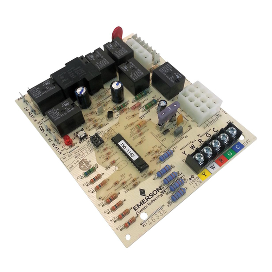
The 50M56-743 kit is an automatic gas HSI Integrated Fur-
nace Control that employs a microprocessor to continually
monitor, analyze, and control the proper operation of the gas
burner, inducer, and fan.
Signals interpreted during continual surveillance of the ther-
mostat and flame sensing element initiate automatic ignition
of the burner, sensing of the flame, and system shut-off during
normal operation.
These controls incorporate system fault analysis for quick gas
flow shut-off, coupled with automatic ignition retry upon sensing
a fault correction.
Installation should be done by a qualified heating and air
conditioning contractor or licensed electrician.
If in doubt about whether your wiring is millivolt, line, or low
voltage, have it inspected by a qualified heating and air
conditioning contractor or licensed electrician.
Do not exceed the specification ratings.
All wiring must conform to local and national electrical codes
and ordinances.
This control is a precision instrument, and should be handled
carefully. Rough handling or distorting components could
cause the control to malfunction.
Following installation or replacement, follow manufacturer's
recommended installation/service instructions to ensure
proper operation.
CAUTION
!
Do not short out terminals on gas valve or primary
control. Short or incorrect wiring may damage the
thermostat.
CONTENTS
Description ................................................................... 1
Precautions .................................................................. 1
Specifications .............................................................. 2
Installation ................................................................... 3
Operation ..................................................................... 6
System Lockout and Diagnostic Features ................... 7
Troubleshooting ........................................................... 8
Integrated Single or Two-Stage
HSI Integrated Furnace Control Kit
INSTALLATION INSTRUCTIONS
50M56-743 Cross Reference Information
0130F00006
0130F00006S
PCB00109
PCBBF109
WARNING
!
Failure to comply with the following warnings could result
in personal injury or property damage.
FIRE HAZARD
• Do not exceed the specified voltage.
• Replace existing control with exact model and
dash number.
• Protect the control from direct contact with water
(dripping, spraying, rain, etc.).
• If the control has been in direct contact with
water, replace the control.
• Label all wires before disconnection when
servicing controls. Wiring errors can cause
improper and dangerous operation.
• Route and secure wiring away from flame.
SHOCK HAZARD
• Disconnect electric power before servicing.
• Ensure proper earth grounding of appliance.
• Ensure proper connection of line neutral and line
hot wires.
EXPLOSION HAZARD
• Shut off main gas to appliance until installation
is complete.
www.white-rodgers.com
www.emersonclimate.com
50M56-743
DESCRIPTION
Goodman
White-Rodgers
PCBBF122
50M56 289
PCBBF122S
PCBBF132
PCBBF132S
PRECAUTIONS
PART NO. 37-7474A
1314
Advertisement
Table of Contents

Related Manuals for White Rodgers 50M56-743


Summary of Contents for White Rodgers 50M56-743
-
Page 1: Table Of Contents
FAILURE TO READ AND FOLLOW ALL INSTRUCTIONS CAREFULLY BEFORE INSTALLING OR OPERATING THIS CONTROL COULD CAUSE PERSONAL INJURY AND/OR PROPERTY DAMAGE. DESCRIPTION The 50M56-743 kit is an automatic gas HSI Integrated Fur- 50M56-743 Cross Reference Information nace Control that employs a microprocessor to continually Goodman... -
Page 2: Specifications
TIMING SPECIFICATIONS (All times are in seconds, unless noted otherwise Event Definition 50M56-743 Pre-Purge The period of time intended to allow for the dissipation of any unburned gas or residual products of combustion at the beginning of a furnace operating cycle prior to initiating ignition... -
Page 3: Installation
Refer to the wiring diagram and wiring table when connecting water, replace the control. the 50M56-743 control to other components of the system. • Label all wires before disconnection when serv- UL approved, 105°C rated 18 gauge, stranded, 2/64” thick icing controls. - Page 4 WIRING TYPICAL SYSTEM WIRING DIAGRAM NEUTRAL (LINE) (LINE) 120 VAC 24 VAC CLASS II TRANSFORMER 24 VAC 50M56 COOL LO HEAT CIRCULATOR HI HEAT BLOWER LINE XFMR PARK PARK INDUCER IND-N IGN-N IGNITOR [4-Pin Connector] CIR N LINE N XFMR N ELECTRONIC EAC N AIR CLEANER...
- Page 5 WIRING TYPICAL SYSTEM WIRING TABLE 50M56 TERMINAL SYSTEM COMPONENT TERMINAL TYPE CONNECTION low voltage thermostat W terminal (or equivalent) low voltage thermostat G terminal (or equivalent) Terminal low voltage thermostat R terminal (or equivalent) block with low voltage thermostat Y terminal (or equivalent) captive (2nd wire from Y terminal goes to 24 VAC HOT side of screws...
-
Page 6: Operation
If flame is not detected, both valves are de-energized, the ignitor is turned off, and the 50M56-743 control goes into the *MODE and 2ND STG DLY for Goodman 50M56-289 only “retry” sequence. The “retry” sequence provides a 60-second... -
Page 7: System Lockout And Diagnostic Features
LED will stay off or flash 8 times. In this case, the entire control should be The 50M56-743 has only one serviceable part –an automotive replaced, as the control is not field-repairable. -
Page 8: Troubleshooting
TROUBLESHOOTING Red LED Flash Error/Condition Comments/Troubleshooting External lockout Failure to sense flame is often caused by carbon deposits on the flame (exceeded retries) sensor, a disconnected or shorted flame sensor lead or a poorly grounded furnace. Carbon deposits can be cleaned with emery cloth. Verify sensor is not contacting the burner and is located in a good position to sense flame.
Need help?
Do you have a question about the 50M56-743 and is the answer not in the manual?
Questions and answers