
Related Manuals for Ametek Thermox TM2000


Summary of Contents for Ametek Thermox TM2000
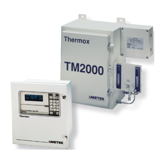
- Page 1 Thermox TM2000 Oxygen Analyzer ® User Manual Thermox 150 Freeport Road PN 90287VE, Rev. T Pittsburgh, PA 15238...
-
Page 2: Offices
If the instrument or procedures are used for purposes over and above the capabilities specified herein, confirmation of their validity and suitability should be obtained; otherwise, AMETEK does not guarantee results and assumes no obligation or liability. -
Page 3: Table Of Contents
General Wiring and Conduit Requirements .........3-18 Control Unit AC Mains Supply Connections ........3-19 Sensor Connections ...................3-22 Current Output Connections ..............3-24 Alarm Contact Connections ..............3-26 Remote Calibration Unit Connections ...........3-28 RS-485 Communications Connections ...........3-30 Option Card Installation .................3-34 Thermox TM2000 Oxygen Analyzer | iii... - Page 4 Furnace Replacement ..................7-6 Parts Replacement List ..................7-7 APPENDIX A SERIAL COMMUNICATIONS APPENDIX B MENU OPTION CHARTS APPENDIX C CURRENT OUTPUTS: OTHER APPLICATIONS APPENDIX D USING SERIES 2000 RCU SIGNALS APPENDIX E DRAWINGS AND CUSTOM INSTRUCTIONS iv | Thermox TM2000 Oygen Analyzer...
-
Page 5: Safety Notes
Grounding Instrument grounding is mandatory. Performance specifications and safety protection are void if instrument is operated from an improperly grounded power source. Verify ground continuity of all equipment before applying power. Thermox TM2000 Oxygen Analyzer | v... -
Page 6: Warning Labels
(ATTEnTion-RiSQuE dE dÉcHARGE ÉlEcTRiQuE) Achtung - Hochspannung lebensgefahr cAuTion - (Refer to accompanying documents) (ATTEnTion-SE RÉFERER AuX docuMEnTS JoinTS) Achtung (Beachten Sie beiliegende dokumente) cAuTion - Hot Surface (ATTEnTion-SuRFAcE cHAudE) Achtung - Heiße Oberfläche vi | Thermox TM2000 Oygen Analyzer... -
Page 7: Electromagnetic Compatibility (Emc)
AC mains or any other circuit that could induce transients into the Analyzer or the overall system. Examples of electrical events and devices known for the generation of harmful electromagnetic disturbances include motors, capacitor bank switching, storm related transients, RF welding equipment, static, and walkie-talkies. Thermox TM2000 Oxygen Analyzer | vii... -
Page 8: Equipment Used In Class I, Division 2 Hazardous Locations
(NEC Sec 501.4(b) or CEC 18-152) and in accordance with the authority having jurisdiction. If the is to be powered by a source of 24 VDC other than that supplied by AMETEK, the TM2000 power source’s output must be isolated from hazardous mains voltages using double or reinforced insulation which has a minimum dielectric strength of 2300 VAC. -
Page 9: Environmental Information (Weee)
Environmental Information (WEEE) This AMETEK product contains materials that can be reclaimed and recycled. In some cases the product may contain materials known to be hazardous to the environment or human health. In order to prevent the release of harmful substances into the environment and to conserve our natu- ral resources, AMETEK recommends that you arrange to recycle this product when it reached its “end of life”. - Page 10 Series 2000 Controller and the PPM RCU also conform to the following safety standarrd: UL 1604 UL Listed Process Control Equipment for Use in Hazardous Locations Manufacturer’s Address in Europe: AMETEK Precision Instruments Europe GmbH Rudolf-Diesel-Strasse 16 D-40670 Meerbusch, Germany Mark Coppler July 2001 Compliance Engineer x | Thermox TM2000 Oygen Analyzer...
- Page 11 MANUFACTURER’S EQUIPMENT, WHETHER SOLD SEPARATELY OR IN CONJUNCTION WITH EQUIPMENT OF OUR MANUFACTURE. WE DO NOT AUTHORIZE ANY REPRESENTATIVE OR OTHER PERSON TO ASSUME FOR US ANY LIABILITY IN CONNECTION WITH EQUIPMENT, OR ANY PART THEREOF, COVERED BY THIS WARRANTY. Thermox TM2000 Oxygen Analyzer | xi...
- Page 12 This page intentionally left blank. xii | Thermox TM2000 Oygen Analyzer...
-
Page 13: Chapter 1 Overview
OVERVIEW Sensor The TM2000 has no operator-serviceable components. An operator should never attempt to open the sensor or controller covers. Refer all NOTE servicing to qualified service personnel. Basic Elements of the Sensor The TM2000 analyzer consists of the following basic systems: •... - Page 14 The oxygen content is then determined from the Nernst equation: 1-2 | Thermox TM2000 Oxygen Analyzer...
- Page 15 where R and F are constants, T is absolute temperature, and O and O are the oxygen partial pressures on either side of the cell. For measuring oxygen in non-combustibles gases, the calibration of an analyzer is obtained from the formula: 20.9% E = A * T * Log AT = 44.0 at 615°C...
-
Page 16: Common Operator Errors
Allow at least one hour after closing the sensor door for readings to stabilize. Allow more time after a cold start-up. • If calibrating in the PPM range, calibration gas should be in cylinders made of aluminum, not carbon steel. 1-4 | Thermox TM2000 Oxygen Analyzer... -
Page 17: Technical Support
Technical Support AMETEK/Thermox is committed to providing the best technical support in the industry. If you need service or application assistance, please call AMETEK at (412) 828-9040, or your local AMETEK/Thermox representa- tive. Before you call the factory for technical support, run test gases and record... - Page 18 This page intentionally left blank. 1-6 | Thermox TM2000 Oxygen Analyzer...
-
Page 19: Chapter 2 Specifications
SpecificationS control Unit Display 4 line x 20 character vacuum fluorescent. Displays combinations of oxygen (0.1 PPM O to 100%, auto-ranging), time and date, cell temperature, user programmable text, thermocouple mV or cell mV. Password protection, programmable pressure compensation and context-sensitive help are also provided. - Page 20 Timed automatic calibration with option- al remote calibration unit. Oxygen cell lifetime extender. Single gas verify that analyzer is within calibration limits. Power Requirements Nominal 115-230 VAC ±10%, 47-63 Hz. max., 75 VA max. 2-2 | Thermox TM2000 Oxygen Analyzer...
- Page 21 Sensor Operating Range 0.1 PPM O to 100% O Accuracy Percent: ±1.0% of reading or .02% O absolute, whichever is greater. PPM: ± 2% of reading or 0.5 PPM O absolute, whichever is greater. Response Time < 5 seconds at 0.6 L/min (1.3 scfh) over one decade. Repeatability Percent: ±0.5% of reading or 0.1% O absolute, whichever is greater.
- Page 22 Indoor/Outdoor; UL Type 4X (NEMA 4X) (IP56) Envoironment: Ambient Temperature: -18° C to 50° C (0° F to 122° F) Humidity: 0 to 90%, non-condensing Max Altitude: 2000 Meters IEC Installation Category: II IEC Pollution Degree 2 2-4 | Thermox TM2000 Oxygen Analyzer...
-
Page 23: Chapter 3 Installation And Start-Up
INSTALLATION AND START-UP The operations in this chapter should be performed only by qualified service personnel experienced with electrical safety techniques. There are no operator-serviceable components inside the TM2000 system, NOTE and an operator should never open the sensor or controller covers. Qualified service personnel should never service the controller or sen- sor unless power has been disconnected from the controller and sensor, and the sensor has been allowed to cool for at least one hour. -
Page 24: Mechanical Installation
Mechanical Installation This section describes how to perform the mechanical installation portion of the system installation. This includes the following: • Sensor Mounting • Sample Gas/Calibration Gas Plumbing Sample Gas/Calibration Gas Requirements Pressure and Flow Requirements Plumbing Option • Clean Gas Remote Calibration Unit Installation Sensor Mounting The TM2000 sensor enclosure is a NEMA 3R (IP54)-rated, polyurethane- coated carbon steel cabinet that can be mounted on a wall or a pole. - Page 25 Figure 3-1. Sensor Mounting (no sample bypass). Installation and Start-Up | 3-3...
- Page 26 Figure 3-2. Sensor mounting (with sample bypass). Sample gas / calibration gas requirements The maximum inlet temperature of the sample gas (or calibration gases) is 70° C (160° F). The sample gas must also be clean and dry. If the sample contains any condensing moisture, you should heat trace the entire sam- ple line to prevent condensation.
- Page 27 For calibration gases, the span gas must have an oxygen content that is a factor-of-ten higher than the zero gas (for example, if the zero gas is 1.0%, the span gas must be 10% or higher. If the zero gas is .1%, the span gas must be 1% or higher).
- Page 28 Special requirements if sample under vacuum If your sample is under vacuum, the inlet sample negative-pressure limit is 10 inches of water (vacuum). If sampling from a negative pressure, you must enter this negative pressure value using the Setup/Process Pressure menu option from the control unit front panel.
- Page 29 Figure 3-3. Manual calibration setup. Figure 3-4. Manual calibration setup with sample bypass. Installation and Start-Up | 3-7...
-
Page 30: Clean Gas Rcu Installation (Optional)
Clean Gas RCU Installation (Optional) This section shows how to use the factory-provided Clean Gas Remote Calibration Unit (RCU) to connect your sample gas, zero calibration gas, and span calibration gas. Once these gases are connected to the RCU, the RCU automatically switches between the sample and calibration gases during an auto calibration . - Page 31 Figure 3-5. Clean gas RCU mounting dimensions. Figure 3-6. Clean gas RCU plumbing connections. Installation and Start-Up | 3-9...
- Page 32 If you have the TM2000 sensor without the sample bypass option: • Connect the sample gas from your process to the sample gas inlet on the RCU (labeled Sample In on the RCU). • Connect the RCU outlet (labeled Sample Out on the RCU) to the inlet of the TM2000 sensor (see Figure 3-7).
- Page 33 Figure 3-8. TM2000 sensor connections (with bypass). Figure 3-9. Clean gas RCU calibration setup. Installation and Start-Up | 3-11...
-
Page 34: Ppm Measurement Suggestions
RCU wiring See the “Wiring” section in the Installation Chapter for help on how to connect wiring between the control unit and the RCU. Once completed, this wiring allows the software in the control unit to turn on the appro- priate valves in the RCU during calibration. - Page 35 Never use Teflon, rubber or plastic tubing. Use stainless steel tubing or refrigerator-grade copper tubing. In general, the tubing must be extremely clean. Even a small amount of contamination in tubing line can affect PPM oxygen readings. Quick Response To improve the response time of the TM2000, use as small a sample tube diameter as possible.
-
Page 36: Control Unit Mounting
Control Unit Mounting The Series 2000 Control Unit comes with various mounting options. • The weatherproof enclosure can be mounted to either a panel, a wall, or to a pole. • The general purpose enclosure can be mounted as a panel, a rack, or a wall mount. Find the section that corresponds to the type of control unit mounting configuration you ordered, then mount as shown in that section. Weatherproof - panel Figure 3-10 shows the panel mounting dimensions for the Series 2000 weather-... - Page 37 Weatherproof wall/z-purge option Figure 3-12 shows the wall- and pole-mounting dimensions for the Series 2000 weatherproof Z-purge enclosure. To mount this control unit version, you must also connect instrument air to the Purge Inlet and set the pres- sure and flow as indicated on the warning tag on the control unit. Z-Purge shutdown procedure Disconnect power to the control unit for one hour while maintaining purge air flow before the door is opened, unless the area is demonstrated...
- Page 38 General Purpose - Panel 9.10 12.6 23.11 32.0 Figure 3-13 shows the panel-mounting dimensions for the Series 2000 general 5.22 6.57 13.26 purpose enclosure. This version can be 5.00 16.69 12.70 mounted in panels up to 1” thick. 10.00 10-32 25.40 3.8 cm (1.5 in.) 10.45...
-
Page 39: Wiring
Wiring Disconnect AC mains power from the controller before performing wiring. Connections to the control unit are made through the wiring card (see Figure 3-16). For the general purpose rack and panel mount versions, the wiring card is located on the rear of the control unit. The wiring card is lo- cated on the front bottom of the control unit for all weatherproof versions and for the general purpose wall mount version. -
Page 40: General Wiring And Conduit Requirements
Any terminals not described in this section are reserved for future use. NOTE This wiring section shows you how to make the following connections: • AC mains supply to control unit • AC mains supply to sensor • Control unit to sensor • Control unit to current output devices • Control unit to alarm devices • Control unit to remote calibration unit • Control unit to host computer (RS-485 communications) This wiring section also provides mandatory grounding and shielding requirements. -
Page 41: Control Unit Ac Mains Supply Connections
• Use the conduit entry point closest to the connections you are making. Do not add any additional conduit entry holes! # of TWISTED SENSOR TYPE GAUGE WIRE PAIRS NEEDED 22 (to 250 ft) TM2000 18 (250 to 1000 ft) Figure 3-17. Recommended sensor cable wiring (minimum acceptable grades). Control Unit AC Mains Supply Connections Follow general grounding and shielding requirements for all wiring as described in the “General Wiring Requirements”... - Page 42 EMC grounding, shielding, and noise protection For EMC purposes, under no circumstances should you leave shields disconnected at one end or both ends of the cable (sensor or control unit or other device). You must use twisted-pair cable in rigid metal conduit or use twisted-pair cable with an overall braided shield.
- Page 43 Transient and RFI interference • Although there are transient and noise protectors on all control unit I/O connections (communications, current outputs, sensor, etc.), this protection is intended to act as a last line of defense against unwanted transient and RFI interference. Proper installation practices to pre- vent the introduction of transients and noise into the system must be followed.
-
Page 44: Sensor Connections
Sensor Connections Follow all general grounding and shielding requirements as described in the “General Wiring Requirements” section at the beginning of this Wiring section. Also make sure that AC mains power has been removed from the control unit and sensor before making sensor con- nections. - Page 45 Sensor AC mains supply connections Connections for AC mains supply to the sensor are labeled as follows: Line Connection Neutral (USA) Chassis Stud Equipment Ground (Protective Conductor) There is no power switch or circuit breaker on the sensor. It must be pro- tected by installing it on a circuit-protected line, maximum 15 amperes, with a switch or circuit breaker in close proximity to the sensor and within easy reach of an operator.
-
Page 46: Current Output Connections
CONTROL UNIT SENSOR TERMINAL LABEL NUMBER cell + (one pair) cell - Furnace (one pair) 15v coM T/c + (one pair) T/c - 15v SPlY (one pair) 15v SPlY Figure 3-21. Standard sensor connections. Current Output Connections Current output connections are labeled as follows on the wiring card of the Series 2000 control unit (see Figure 3-22): IOUT1 + and - IOUT2 + and -... - Page 47 Figure 3-22. Current output connections example. Installation and Start-Up | 3-25...
-
Page 48: Alarm Contact Connections
Alarm Contact Connections Follow general EMC grounding and shielding requirements for all wiring as described in the “General Wiring Requirements” section at the beginning of this Wiring section. This section describes how to make wiring connections for any alarm devices you want to connect to the control unit. Information on how to set up alarms in software is described in the Controller/User Interface chapter. - Page 49 Oxygen Alarm connections are configurable in software to activate under a variety of user defined conditions, and are labeled as follows: ALARM 3A ALARM 4A ALARM 3B ALARM 4B Figure 3-23. Series 2000 Alarm Connections Example. Installation and Start-Up | 3-27...
-
Page 50: Remote Calibration Unit Connections
Remote Calibration Unit Connections If you don’t have the remote calibration unit (RCU) option, skip this sec- tion. Remote Calibration Unit (RCU) wiring connections between the Series 2000 control unit wiring card and the RCU are as shown in Figure 3-24 and Figure 3-25. - Page 51 Figure 3-25. Series 2000 controller RCU connections. Installation and Start-Up | 3-29...
-
Page 52: Rs-485 Communications Connections
RS-485 Communications Connections The Series 2000 control unit has the ability to communicate with other computers that use the same protocol and have the same hardware in- terface. See the Serial Communication Appendix for information on the RS-485 serial communications protocol. 2-wire connections The connections used for RS-485 2-wire communications on the wiring card are labeled as follows:... - Page 53 Figure 3-26. Series 2000 2-wire RS-485 communications connections. Installation and Start-Up | 3-31...
- Page 54 4-wire connections The connections used for the RS-485 4-wire communications on the wir- ing card are labeled as follows: 4WTX+/2W+ 4WTX-/2W- 4WRX+ 4WRX- Connect all control unit 4WTX+, 4WTX-, and all 4WRX+ and 4WRX- con- nections in parallel in a daisy chain fashion. Make the following con- nections between the host computer and the controller in a daisy-chain fashion (see Figure 3-27): Host Computer TX- to Controller 4WRX-...
- Page 55 Figure 3-27. Series 2000 4-wire RS-485 communication connections. Installation and Start-Up | 3-33...
-
Page 56: Option Card Installation
Option Card Installation This section shows you how to add an auto calibration card to the control unit. If you ordered this option when you first purchased your analyzer, this option card will already be installed in your control unit. This section shows you how to install an option card if you later add that option to the control unit. - Page 57 Figure 3-28. Front view of Series 2000 Control Unit. Adding an Option Card Open the access door below the display module (hinges down). Pull on the handle of the power supply/keypad module and remove this module from the control unit (it slides out). Insert the option card into any of the three available slots underneath the display module.
- Page 58 This page intentionally left blank. 3-36 | Thermox TM 2000 Oxygen Analyzer...
-
Page 59: Chapter 4 Controller / User Interface
CONTROLLER / USER INTERFACE Series 2000 User Interface This chapter provides a brief overview on how to use the Series 2000 con- trol unit. This includes the following topics: Areas of the Control Unit Password Restrictions Control Unit Display ... - Page 60 Display option from the Setup Key. Note that you can also use the Display menu option to place your own text messages on one or more of the first three lines. The last display line is reserved for system and error messages. 4-2 | Thermox TM2000 Oxygen Analyzer...
- Page 61 If an alarm condition exists, alarm information in the form of an Up or Down Arrow (corresponding to a high or low alarm) will appear next to the oxygen reading on that display line. See the Alarm Key section for de- tails on setting alarms.
- Page 62 Passwords option from the Setup Key, you would select the Setup Key, then move the arrow pointers to the Passwords option and press the Help Key. You would then receive on-line help on the Password option. 4-4 | Thermox TM2000 Oxygen Analyzer...
-
Page 63: Setup Key
Setup Key Setup Display Password System Process Pressure Tests System Primary Serial # Calibrate Sensor Communications Configuration Figure 4-2. Remote Switch Configuration Remote Switch Setup Key Menu Configuration Options The Setup Key (Figure 4-2) allows you to do the following: Define what information to place on each display line (Display). - Page 64 Primary calibration bration. Sensor Configuration Select sensor type. Define communications parameters. communications Define wheather digital input should start an automatic Remote Sensor Configuration calibration or an automatic verify. Figure 4-3. Overview of Setup Key functions 4-6 | Thermox TM2000 Oxygen Analyzer...
- Page 65 Display This menu option allows you to define what information should appear on the top three display lines of your Series 2000 control unit. Choices for each line are as follows: Cell temperature Cell millivolts Thermocouple millivolts (T/C millivolts) ...
- Page 66 PPM scale. Hydrocarbon upset condition If the system detects that the oxygen level is 0, and you have selected Hydrocarbon Upset from the Setup/Sensor Config option, the system will display hydrocarbon upset condition information. 4-8 | Thermox TM2000 Oxygen Analyzer...
- Page 67 You can also use this menu option to disable the password requirement. Setting Up a System Password If you have forgotten the correct password, you can call AMETEK/ Thermox and a service password will be provided so you can access this option and enter a new system password.
- Page 68 If the correct pressure has been entered into the system, press the En- ter Key without entering a new value to exit this menu option. If the pressure was incorrectly entered, you can reenter it at this point. 4-10 | Thermox TM2000 Oxygen Analyzer...
- Page 69 This menu option allows you to check the Series 2000 control unit for possible problems and to isolate where the problem might be. You may be asked by AMETEK/Thermox personnel to access this menu option to perform system diagnostics. Performing these tests is not required under normal operations.
- Page 70 System Serial # This menu option allows you to view your system serial # and manufac- turing #. You may be asked by AMETEK/Thermox personnel to provide this information upon request. Setting Up the Serial Number Select System Serial # from the Setup menu.
- Page 71 Primary Calibration The actual furnace temperature set point will vary from unit-to-unit based upon the Primary Calibration which correlates the actual cell response for the desired 615°C cell set point temperature with the actual furnace thermocouple feed back temperature. This is accomplished by applying two known concentrations of oxygen to the analyzer during the primary calibration.
- Page 72 Perform a primary calibration on your system rather than a regular calibration (from the Calibrate Key) in the following cases: When you replace your zirconium oxide oxygen cell. When your system fails a regular calibration. 4-14 | Thermox TM2000 Oxygen Analyzer...
- Page 73 You should always try to do a regular calibration before resorting to a primary calibration in all cases except when you install a new cell. If a regular calibration doesn’t work correctly, see the Calibration Checks NOTE section in the Troubleshooting chapter for possible calibration setup problems affecting the calibration.
- Page 74 You may need to reenter your alarm setpoints and configura- NOTE tion. Once a hydrocarbon upset condition is reached (and assuming you select- ed Hydrocarbon Upset), the display switches from displaying the oxygen reading to displaying a hydrocarbon condition text message. 4-16 | Thermox TM2000 Oxygen Analyzer...
- Page 75 Communication This menu option allows you to define RS-485 communications param- eters between the Series 2000 control unit and a host device. This includes the following: Baud Rate This parameter allows you to define the baud rate that the control unit and the host computer are using to communicate.
- Page 76 Configuring the Remote Switch To define whether the digital input should trigger an automatic calibration or an automatic verify, do the following: Select Remote Switch Config from the Setup Key. Select Calibrate or Verify. 4-18 | Thermox TM2000 Oxygen Analyzer...
-
Page 77: Analog Range Key
Analog Range Key Analog Range Current Range Track/Hold Current Mode Output Filtering Figure 4-4. Select Analog Range Key Function menu options The Series 2000 control unit allows you to direct process readings to either of the two analog output ports on the bottom front of the control unit. See the “Select An Analog Output Port”... - Page 78 Set current Mode 0 to 20 mA 4 to 20 mA output Filtering Smooth out variations in readings Select Function cell Temperature cell Millivolts Thermocouple Millivots Figure 4-5. Overview of Analog Range Key functions. 4-20 | Thermox TM2000 Oxygen Analyzer...
- Page 79 System Password System passwords are created using the Setup Key. Please see the “Setup Key” section for information on defining or disabling a system password. NOTE If a system password is enabled, you will be required to correctly enter this password before accessing Analog Range Key functions.
- Page 80 Type the value to correspond to the 20 mA analog output. If tracking oxygen, select whether you want to enter the 0 or 4 mA value using a percent or PPM range. 4-22 | Thermox TM2000 Oxygen Analyzer...
- Page 81 You will then be prompted to define the value to correspond to the 0 or 4 mA analog output: Out # y 4 ma = xx New Value? where y is the analog output port and xx is the value that the current out- put currently represents.
- Page 82 Hold during verify Track during verify After you select one of these options, your choice will be confirmed on the display: Out # 1 will TRACK during Verify Out # 1 will HOLD during Verify 4-24 | Thermox TM2000 Oxygen Analyzer...
- Page 83 Set Current Mode Option The Set Current Mode menu option allows you to define either a 0-to-20 or 4-to-20 mA analog output range for the selected analog output port. This output is dependent on both the range of readings you define (see the “Set Current Range”...
- Page 84 Range menu option where you choose the range of readings that the 0 to 20 mA or 4 to 20 mA analog output represents (see the “Set Current Range” section in this chapter for details). 4-26 | Thermox TM2000 Oxygen Analyzer...
-
Page 85: Alarm Key
Alarm Key Alarm Key Alarm Set Points Alarm Configure Relay Configure Select Function Exception Figure 4-6. Alarm Key menu. Alarms 1 and 2 are hard wired for the watchdog timer and service alarms. They are not selectable in software. NOTE Oxygen alarms are disabled during a primary or regular calibration. - Page 86 The Select Function menu option applies only to Alarm 3. The Relay Configure menu option applies to all alarms except for the watchdog and service alarms, which always de-energize on alarm (fail safe). 4-28 | Thermox TM2000 Oxygen Analyzer...
- Page 87 FUNCTION Alarm Configure Relay Configure *Select Function Alarm 3 High o Alarm Energize on alarm Low O cal Start Alarm verify Start (only selectable if Select Function is de-energize on alarm oxygen) (disabled during calibration cycle and during system alarm condition) Alarm 4 High o...
- Page 88 You are then prompted to enter the Alarm 4 set point value: Alarm #4 =xx New Value? Enter the Alarm 4 set point value. Press the Cancel Key or the Enter Key to then exit this menu option. 4-30 | Thermox TM2000 Oxygen Analyzer...
- Page 89 Alarm Configure This menu option allows you to define whether alarms should trigger based on a high alarm or a low alarm condition. Whether Alarm 3 is set high or low applies only if it is set to track oxygen levels (% O ).
- Page 90 Alarm 3 should be associated with oxygen levels, or with the start of a calibration or verification. The control unit automatically exits you from this menu after you make your selection. 4-32 | Thermox TM2000 Oxygen Analyzer...
-
Page 91: Service Alarm
Service Alarm The service alarm operates as normally closed (service alarm condi- tion causes open contacts). NOTE The service alarm provides an alarm that alerts you of possible system problems that require attention. Events that can trigger the service alarm to activate are as follows: •... -
Page 92: Exception Log
Pressing the Down Arrow Key shows later exception log entries. Press- ing the Up Arrow Key shows more recent exception log entries. Press the Cancel Key at any time to exit this menu option. 4-34 | Thermox TM2000 Oxygen Analyzer... -
Page 93: Chapter 5 Calibration
CALIBRATION Calibrate Initiate Cal Initiate Verify Cal/Verify Data Cal Gas Value Inject Cal Set Cal Timers Figure 5-1. Configure Calibrate Key menu Verify options. The Calibrate key allows you to use the Series 2000 control unit to cali- brate your analyzer. The Series 2000 control unit provides features that make calibrating your analyzer easy and even includes a way for the system to periodically calibrate itself. -
Page 94: Definitions
Manual Calibration - You must physically switch the gases because you are not using an RCU. However, you still define the calibration gas values. 5-2 | Thermox TM2000 Oxygen Analyzer... -
Page 95: Overview
Overview The Calibrate key allows you to do the following (see Figure 5-2) : • Initiate an automatic, remote, or manual calibration or verification. Although automatic calibrations can be set to run at predetermined frequencies, you can also force the system into an automatic calibra- tion (Initiate Cal and Initiate Verify). • View previously collected calibration or verify data (Cal/Verify Data). -
Page 96: Aborting A Calibration
If you press the Calibrate key while the system is performing a calibration, you will be have the option to either abort or to continue the calibration. All other menu functions are temporarily disabled during a calibration 5-4 | Thermox TM2000 Oxygen Analyzer... -
Page 97: Password
Password System passwords are created using the Setup key. Please see the “Password” section in the Setup Key chapter for information on defin- ing or disabling a system password. NOTE If a system password is enabled, you will be required to correctly enter this password before accessing certain Calibrate key functions. - Page 98 • Define a time period for the system to recover from reading the cali- bration gas value to reading process gases (Set Cal Timers/Recovery Duration). Start the auto calibrate as follows: Select the Initiate Cal option from the Calibrate key menu. Select Auto Calibrate. 5-6 | Thermox TM2000 Oxygen Analyzer...
- Page 99 The system will begin the automatic calibration and will notify you how long the span gas will be applied to the sensor from the RCU: Zero Gas xx:xx System Calibrating During this time, the RCU has switched the solenoid valves and has intro- duced the zero gas to the sensor.
- Page 100 O zero gas using the Cal Gas Values menu option. This O zero gas set point value should match the cal gas cylinder for the O zero gas connected to your RCU. 5-8 | Thermox TM2000 Oxygen Analyzer...
- Page 101 Then the system will display the recovery time remaining: Recovery xx:xx System Calibrating After the recovery period, the system returns to process readings. Manual Calibrate To perform a manual calibration, follow these steps: Enter the calibration gas value to match the zero calibration gas you intend to use to calibrate your system (Cal Gas Values).
-
Page 102: Initiate Verify
2000 control unit and have a Remote Calibration Unit (RCU). If the Series 2000 control unit detects that these options are not installed, it will auto- matically prompt you with a manual verify when you select the Initiate Verify menu option. 5-10 | Thermox TM2000 Oxygen Analyzer... - Page 103 Automatic verifies can also be set to run at predetermined frequencies using the cycle times you define using the Set Cal Timers/Set Auto Timers menu option. Once you’ve set these cycle times, you don’t need to select the Initiate Verify menu option to run an automatic verify. See the “Remote Calibration Unit Connections”...
- Page 104 RCU. 5-12 | Thermox TM2000 Oxygen Analyzer...
- Page 105 When performing a primary calibration or the first calibration after a pri- mary calibration, the reading and the set point values often won’t match. Once the first regular calibration after a primary calibration is performed, the readings should match. Then the system will display the recovery time remaining: Recovery xx:xx System Verifying Cal After the recovery period, the system returns to process readings.
- Page 106 Then, if you specified a recovery time, the system will display the recov- ery time remaining: Recovery xx:xx System Verifying Cal The system then returns to monitoring process readings. 5-14 | Thermox TM2000 Oxygen Analyzer...
-
Page 107: Cal/Verify Data
Cal/Verify Data This menu option allows you to view the results of the latest calibration or verification. For calibration data, this includes the following: • Span calibration gas value vs. span calibration gas reading. • Zero calibration gas value vs. zero calibration gas reading. • Span calibration gas drift. • Zero calibration gas drift. For verify data, the display shows information on the verify gas. The terms Span Gas and Zero Gas used in this section refer to the calibra- tion gas values you enter using the Cal Gas Values menu option. - Page 108 If the date or time has not been set or a verify has not been performed before, random characters will appear instead of the time and date when the verification was completed. If this occurs, reset the analyzer ’s time and date. 5-16 | Thermox TM2000 Oxygen Analyzer...
-
Page 109: Cal Gas Value
Cal Gas Value This menu option allows you to enter the zero calibration gas value to match the calibration gas cylinder you use to calibrate your system. To set your verify gas value, use the Configure Verify menu option instead. • Span Gas - high calibration gas • Zero Gas - low calibration gas The Span Gas value you enter must be higher than the Zero Gas value... -
Page 110: Inject Cal Gas
ENTER for next Gas. CANCEL to quit. When you have adjusted the pressure and flow for the span gas to the desired levels, press the Enter key. 5-18 | Thermox TM2000 Oxygen Analyzer... - Page 111 The following message will then appear on your display, indicating that the RCU has now switched the solenoid valves and has introduced the zero gas to the sensor: Zero gas is flowing Adjust the pressure and flow for the zero gas to the desired levels. You will then be prompted to end the cycle: CANCEL to quit Press the Cancel key to end the cycle.
-
Page 112: Set Cal Timers
• Enable or disable the auto calibration cycle (Auto Cal On/Off). • Define how long cal gases should flow through the sensor during automatic calibrations or verifications (Cal Gas Duration). • Define a recovery duration, during which time the sensor switches from measuring calibration gas readings to measuring process read- ings without affecting the analog output or triggering of alarms (Re- covery Duration). 5-20 | Thermox TM2000 Oxygen Analyzer... - Page 113 Set Cal Timers - Set Auto Timers This menu option allows you to set the frequencies for automatic calibra- tions or verifications, including the time when the first calibration or veri- fication starts. You have the option of setting the cycle in either hours or days.
- Page 114 Hr: Mn text. The Series 2000 control unit uses military time so 16:00 equals 4:00 PM., and 04:00 equals 4:00 AM. If the current time is correct, press the Enter key without changing the value. 5-22 | Thermox TM2000 Oxygen Analyzer...
- Page 115 You are then prompted to enter the correct date: The date is: YY/XX/ZZ Enter date: Mo/Da/Yr As you type the new date, it overwrites the mo/da/yr text on the dis- play. Enter the month, the day, the year, then press the Enter key. If the current date is correct, press the Enter key without changing the value.
- Page 116 Mn equals minutes and Sc = seconds. As you type the new zero gas duration time, it overwrites the Mn:Sc text. If you wish to use the currently displayed time, press the Enter key without entering any text. 5-24 | Thermox TM2000 Oxygen Analyzer...
-
Page 117: Configure Verify
Set Cal Timers - Recovery Duration This menu option applies to all automatic, remote, and manual cali- brations and verifications. NOTE This menu option allows you to define a recovery time so the control unit can return to reading process gases after reading calibration gases without affecting the analog outputs or the triggering of alarms. - Page 118 Failure message will appear on the bottom line of the display, and NOTE the Service Alarm will trip. The error message will continue to be displayed until a successful verify is completed (gas value within the range) or a successful calibration is completed. 5-26 | Thermox TM2000 Oxygen Analyzer...
-
Page 119: Chapter 6 Maintenance And Troubleshooting
MAINTENANCE AND TROUBLESHOOTING The operations in this chapter should be performed only by qualified service personnel with a knowledge of electrical safety techniques. There are no operator-serviceable components inside the TM2000 system. An operator should never remove the cover from the controller or sensor. Qualified service personnel should never service the controller or sensor unless power has been disconnected from the controller and the sensor, and the sensor has been allowed to cool for at least one hour. -
Page 120: System Messages
This message will not clear from the display by removing or restoring power to the control unit. Cal Verify Aborted This message notifies the operator that the verification was successfully aborted by the system. 6-2 | Thermox TM2000 Oxygen Analyzer... - Page 121 Power Down Detected The system detected that the power was removed. For example, a power outage would cause this message to display. You can acknowledge this system message by setting or reading any user-programmable value and this will clear the message from the display. The message will not clear by removing and restoring power to the unit.
-
Page 122: Error Messages
Incorrect flow rates between calibration gases Process pressure incorrectly entered Failed cell (primary calibration should be run at this time) Leak or plug in plumbing Cell lead wires polarity reversed 6-4 | Thermox TM2000 Oxygen Analyzer... - Page 123 Memory is Corrupted This error message indicates that the control unit’s internal EEPROM memory has been corrupted or a significantly new version of software has been installed in the control unit. Under these conditions, the software will reprogram the EEPROM with factory defaults. You can acknowledge this error message by setting or reading any user-programmable value and this will clear the message from the display.
- Page 124 Shorted thermocouple Faulty interconnecting wiring Control unit display module failure Sensor board failure If this message is soon followed by a “Thermocouple Failure” message, see that message for troubleshooting instructions. 6-6 | Thermox TM2000 Oxygen Analyzer...
- Page 125 Thermocouple Failure This error message occurs when the indicated sensor temperature fall below -70° C. This error message can be the result of one of the following: Open thermocouple Faulty interconnecting wiring Control unit display module failure Verify Failure This error message occurs if the verify gas does not read within the range you defined.
-
Page 126: Diagnostic Checks
Open thermocouple Disconnect power to the control unit and the sensor. Measure across ter- minals “C” and “D” on the sensor board with an ohm meter. If an open is measured, replace the thermocouple. 6-8 | Thermox TM2000 Oxygen Analyzer... - Page 127 Shorted/failed thermocouple Check that the thermocouple leads are not shorted to chassis ground. To do this, use an ohm meter to measure between terminal C on the sensor board and chassis ground, and between terminal D on the sensor board and chassis ground.
- Page 128 The change was implemented on later sensor board designs (80471SE, 80485SE, 80467 SE and 80505SE) due to the confusion caused by see- ing a display that was approximately 12 mVs higher than the voltage measured at the terminals on the wiring board. 6-10 | Thermox TM2000 Oxygen Analyzer...
- Page 129 Calibration Setup Checks Calibration gas check Check that the correct calibration gas values have been entered into the control unit. To do this select the Cal Gas Value menu option from the Calibrate Key on the control unit and check that the calibration gas values entered match the analyzed concentration of the cylinders.
- Page 130 If the cell millivolt signal decreases, troubleshoot to find the leak, then repeat Steps 1 through 7. Possible source of leaks include: 1) the sample gas line, 2) compression fittings, and 3) a cracked cell. 6-12 | Thermox TM2000 Oxygen Analyzer...
- Page 131 Plumbing Leak To check for plumbing leaks, disconnect all power form the RCU and pressurize the inlets. Apply a leak detecting liquid along the base of the solenoids and any plumbing fittings. Repair any leaks found. Solenoid Not Energizing The solenoid drive signal is a 15 VDC signal. This is used to open the ap- propriate calibration gas solenoid.
- Page 132 32 ohms for 115 V furnance and 130 ohms for 230 V furnace (+/- 10%) at room temperature. Add 5% if the furnace is still hot. If the furnace resistance is not within allowable tolerances, replace the furnace. 6-14 | Thermox TM2000 Oxygen Analyzer...
- Page 133 Loss of AC power to the furnace Verify the correct line voltage at L1 and L2 of the sensor board. With line voltage present, check the voltage at terminals R and S on the sensor board. (The voltage at terminals R and S will be either on or pulsat- ing on and off.) If voltage is present and the system is not heating, discon- nect power and check the furnace resistance.
- Page 134 Check for leaks or plugged plumbing in the sensor. Check that the cell is hot enough. If this does not solve the problem, replace the cell and run another prima- ry calibration and a regular calibration after the primary calibration. 6-16 | Thermox TM2000 Oxygen Analyzer...
-
Page 135: General Troubleshooting
General Troubleshooting Your system may pass calibrations yet still seem to be reading incorrect oxygen levels. If this is the case, check the following. Leak Check Leaks can lead to inaccurate readings especially if operating under a sig- nificant pressure or vacuum. Check that all compression fitting and pipe thread connections are leak tight. -
Page 136: Auto Calibration Card Leds
O2 span gas should be flowing into the sensor. Zero When lit indicates that the O zero gas solenoid is energized and the zero gas should be flowing through the sensor. 4 through 12. - not used. 6-18 | Thermox TM2000 Oxygen Analyzer... -
Page 137: Chapter 7 Service And Parts
SERVICE AND PARTS The operations in this chapter should be performed only by qualified service personnel with a knowledge of electrical safety techniques. There are no operator-serviceable components inside the TM2000 system. This appendix shows you how to replace system parts, and is divided into the following sections: • Thermocouple Replacement • Cell Replacement... - Page 138 (up to 500° F, 260° C inside the cover), even after power has been removed from the sensor. Use caution and wear appropriate gloves when handling system components! CAUTION • Always use a backup wrench when working on sensor plumbing. This helps to prevent damaging welds and distorting sensor plumbing. 7-2 | Thermox TM2000 Oxygen Analyzer...
-
Page 139: Thermocouple Replacement
Thermocouple Replacement Disconnect power from the sensor and control unit and allow the sen- sor to cool before replacing parts inside the sensor. To remove the thermocouple, do the following: 1. Disconnect thermocouple wires (red and yellow) from terminals C and D on the sensor board and pull these wires through the conduit hole connecting the sensor board to the sensor. - Page 140 Cell Cell Clip Ceramic Washers O-Ring Fitting Ferrule Cell O-Ring Inlet Tube Cell Fingers Figure 7-1. Cell replacement. Figure 7-2. Furnace replacement. 7-4 | Thermox TM2000 Oxygen Analyzer...
-
Page 141: Cell Replacement
Cell Replacement Disconnect power from the sensor and control unit and allow the sen- sor to cool before replacing parts inside the sensor To replace the cell (see Figure 7-1 and Figure 7-2 for help): Remove the two bolts, flat washers and lockwashers (see Figure 7-2). Keep this hardware for when you reinstall the furnace over the cell. -
Page 142: Furnace Replacement
Reverse the actions taken in step 1 and 2 above. For the thermocouple wires, the red wire connects to terminal D, the yellow wire connects to terminal C. Polarity is not required for the furnace wires. 7-6 | Thermox TM2000 Oxygen Analyzer... -
Page 143: Parts Replacement List
P/N 80439SE Wiring Card P/N 80457SE When ordering, provide the serial number of your analyzer to ensure proper parts are ordered: AMETEK Process and Analytical Instruments Division 150 Freeport Road Pittsburgh, PA, USA 15238 Phone: (412) 828-9040 Fax: (412) 826-0399... - Page 144 This page intentionally left blank. 7-8 | Thermox TM2000 Oxygen Analyzer...
-
Page 145: Appendix A Serial Communications
SERIAL COMMUNICATIONS Communication Protocol Communicating to the Series 2000 control unit through the RS-485 serial port requires the following communication parameter settings: 8 data bits 1 stop bit No Parity In addition, the baud rate on the Series 2000 control unit must match the baud rate of the host device. - Page 146 Command Message Format Start Character Node Address Command Data Checksum End Character Letter “>” (AScii deci- 2 hex Ascii (See com- (n characters 2 hex AScii cariage return mal character 6) characters mands sec- - depends on characters (AScii decimal (00-FF) tion for list of command)
- Page 147 General Serial Communication Commands This section provides general serial communication commands. Program- ming commands and Factory setup commands are provided later in this chapter. Normally, you will use these general serial communications com- mands. Read Number (F) This command allows you to read the value of a variable stored in the Series 2000 Controller.
- Page 148 Read Date and Time (M) This command is used to read the dates and times stored in the Series 2000 Controller. The data consists of a single digit where 0 is used to read the current date and time, 1 is used to read the date and time of the last calibration, and 2 is used to read the date and time of the last verification.
- Page 149 Development Serial Communication Commands These commands are used during initial serial communication design. Echo (A) The echo command is used to test the serial protocol and line integrity. Any text sent to the Series 2000 Controller is echoed back to the host. Bad Command (B) Just returns a bad command (error code 01) reply.
- Page 150 Command List This section provides the command letters you can use. Command Letter Description Echo Bad command Acknowledge Read number calibrate Write number data Format Read date and Time Set date and Time Figure A-1. Serial communication commands list. A-6 | Thermox TM 2000 Oxygen Analyzer...
- Page 151 Responses The Series 2000 Controller returns a variety of responses that can be bro- ken into two categories, success and failure. Success All successful responses start with an A. If there is data returned, it will follow the A and have a checksum after it. All responses end with a car- riage return.
- Page 152 Failure Codes are as follows: Failure Code Description Bad command letter Bad checksum input overrun in serial communica- tion Parameter out of range Error in receipt of a character Cannot calibrate/verify now internal error illegal access (read-only version) Figure A-2. Failure code list.
- Page 153 Variable Table Figure A-3 provides a summary of the variable locations, names, and de- scriptions available. If you need access to more advanced variables, please call AMETEK. Location Name Description Read/Write *Format Flags_3 (see Table A-4) Read Only H (1 byte)
- Page 154 Description Read/Write Format sensor at op.temp. over/under temp inject cal gas active Read Only 1 = true 0 = false auto cal is active auto verify is active reserved reserved cal/verify not permitted Figure A-4. Flags_3 variable table. A-10 | Thermox TM 2000 Oxygen Analyzer...
- Page 155 Description Read/Write Format temperature rise failure cell is over temperature zero gas range error span gas range error primary calibration memory is corrupted excessive cal error Read only 1 = true 0 = false calibration required thermocouple failure thermocouple compensation failure verify aborted calibration aborted system verifying...
- Page 156 Description Read/Write Format relays energize on alarm 1 = true, 0 = false auto cal time is set 1 = true, 0 = false cal timer enabled 1 = false, 0 = true real time clock is set 1 = true, 0 = false Reserved auto verify time is set 1 = true, 0 = false...
- Page 157 Description Read/Write * Format track/hold output #1 during cal 1=track, 0 = hold track/hold output #1 1 = track, 0 = hold current mode select for output #1 1 = 0 - 20 mA 0 = 4 - 20 mA Reserved track/hold output #2 during verify 1 = track, 0 = hold...
- Page 158 Sample Program This section provides a sample Quick Basic program that reads and writes to the serial port: DECLARE FUNCTION Checksum$ (M$) ‘Serial test routine ‘ Continuously sends a message and prints the string returned ‘Open the communications port OPEN “COM2:9600,N,8,1 “FOR RANDOM AS #1 ‘String to be echoed T$ = “Test message”...
-
Page 159: Appendix B Menu Option Charts
MENU OPTION CHARTS SETUP KEY Functions/Options Menu Options Select info for display line 1. display Select info for display line 2. Select info for display line 3. Passwords Create a system password Select a positive or negative process pressure. Process Pressure Enter process pressure value. - Page 160 Auto cal on/off Auto cal on/off Auto verify on/off cal Gas duration Span Gas Time (verify gas time if verifying) Zero Gas Time Recovery duration Enter Recovery Time Figure B-3. Calibrate Key/Set Cal Timers sub-menu. B-2 | Thermox TM2000 Oxygen Analyzer...
- Page 161 ALARM KEY FUNCTIONS/OPTIONS MENU OPTIONS Alarm Set Points Alarm 3 value Alarm 4 value Alarm Configure High o Alarm Low O (For Alarms 3 And 4) Alarm Relay Configure Energize on Alarm de-Energize on Alarm Select Function (applies to Alarm 3 only) Start of calibration Start of verify Exception log...
- Page 162 This page intentionally left blank. B-4 | Thermox TM2000 Oxygen Analyzer...
-
Page 163: Appendix C Current Outputs: Other Applications
CURRENT OUTPUTS: OTHER APPLICATIONS This appendix describes how to do the following: • Modulate external power loop using current outputs. • Power current outputs from an external power supply. Powering Current Outputs from an External Power Supply The Series 2000 control unit wiring card contains a set of terminals that can be used to connect an external voltage source to power the standard current outputs: VEXT1,2 + VEXT1,2 -... - Page 164 IOUT2+ terminal. For each current output channel used in a current loop modulation ap- plication, the jumpers should be removed for that channel. C-2 | Thermox TM2000 Oxygen Analyzer...
- Page 165 OPTIONAL OUTPUT DEVICE EXTERNAL LOOP (COMPUTER OR POWER SUPPLY CHART RECORDER) MAX VOLTAGE MAX LOAD RESISTANCE 30 VOLTS DC 1200 OHMS Figure C-1. Modulation of external power supply. Current Outputs: Other Applications | C-3...
- Page 166 This page intentionally left blank. C-4 | Thermox TM2000 Oxygen Analyzer...
-
Page 167: Appendix D Using Series 2000 Rcu Signals
USING SERIES 2000 RCU SIGNALS You can use Series 2000 control unit signals to control your own switching valve to switch from the sample to calibration gases. Note, however, that we recommend that you use the Factory-Provided Remote Calibration Unit (RCU) as the best way to control the calibration process. You must have and auto calibration card installed in your Series 2000 ... - Page 168 This page intentionally left blank. D-2 | Thermox TM2000 Oxygen Analyzer...
-
Page 169: Appendix E Drawings And Custom Instructions
DRAWINGS AND CUSTOM INSTRUCTIONS This appendix provides any custom drawings or instructions you have ordered. If you didn’t order any cutome options, the standard Intercon- nect drawing is provided. If you ordered special options, the drawings or special instructions pro- vided here supercede any drawings or options provided elsewhere in the manual. - Page 170 This page intentionally left blank. E-2 | Thermox TM2000 Oxygen Analyzer...
Need help?
Do you have a question about the Thermox TM2000 and is the answer not in the manual?
Questions and answers