
Related Manuals for EPAK DS6 PRO


Summary of Contents for EPAK DS6 PRO
- Page 1 Installation and User Manual Maritime TVRO systems DSi6Ku Pro DS6 PRO DS9 PRO DS13 PRO Page 1/33 Doc ID 0354 15.12.20...
- Page 2 The serial number (standard format: 090UC.10.1843.0000) will be required for all service requests regarding this product. You can find the serial number of your EPAK TVRO system both engraved on the chassis of the antenna (Figure 1) and on the delivery note sent to you with the system.
-
Page 3: Table Of Contents
Table of Contents 1 Introduction..............................4 2 Safety Recommendations & Precautions......................5 2.1 Radar interference............................5 2.2 Exposure to rain / moisture......................... 5 2.3 Necessity of grounding the equipment....................... 5 2.4 Power supply.............................. 5 2.5 Maintain ambient temperature for IDU....................... 5 2.6 Maintain ambient temperature for ODU...................... -
Page 4: Introduction
Introduction Intended readers This is an installation and user manual for the EPAK TVRO systems PRO Series, intended for installers of the system and service personnel. Personnel installing or servicing the system must be properly trained and authorized by EPAK. It is important that you observe all safety requirements listed in the beginning of this manual, and install the system according to the guidelines in this manual. -
Page 5: Safety Recommendations & Precautions
The ACU requires 90-264V AC @ 47-63 Hz Input voltage & frequency. The ACU then supplies DC power to the Antenna. Use of an online UPS is mandatory for EPAK systems, otherwise the warranty becomes void. For more details see 4.8. -
Page 6: System Components List
DS13 : 12 mounting screws TVRO manual TVRO manual for easy operation & configuration of the system. Up-to-date documents are available for download on www.epak.de/en. Add-ons (Optionally supplied by EPAK) Component Description LTE Antenna 3G/4G Outdoor Antenna for low-cost coastal internet... -
Page 7: Installation Procedure
Installation Procedure The installation of our systems is easy compared to existing TVRO systems. This section gives a guideline and answers all your questions on how and where to install the ODU and IDU. It is highly recommended to plan your installation according to this in-order to prevent mistakes and damages to the vessel or the TVRO system. -
Page 8: Radar Interferences
4.2.3 Radar interferences Figure 4.2: Minimum safe distance from radar It is very important to not install the antenna near the radar. Radars and satellite antenna's operate in the microwave region of the electromagnetic spectrum. A radar placed close to the ODU can degrade the antenna's performance. -
Page 9: Drilling
Use suitable coax cables: double shielded RG6/RG11 with solid copper core is recommended for the • connection between ACU and the antenna. EPAK warranty does not cover decreased performance due to improper wiring. The maximum recommended cable length for RG6/RG11 is 50m. Make sure that the cable length •... - Page 10 Dimensions and drilling patterns Click for full view or refer to page 30 Figure 4.3: Dimensions 60 cm antenna dome (front and bottom) Click for full view or refer to page 31 Figure 4.4: Dimensions 90 cm antenna dome (front and bottom) Click for full view or refer to page 32...
-
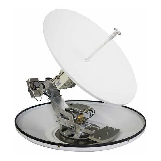
Page 11: Installing The Antenna
Installing the Antenna Before installing the antenna, please take the following precautions: Caution: The radome has to be properly fixed on the antenna before installing it on the platform. • For safety during transport, the antenna has locks for the movement in skew, elevation, roll and •... -
Page 12: Installing The Indoor Unit
Step 1 Release the skew movement by turning the handle into upward position as shown in the figure. Step 2 Release the elevation movement by turning the handle to downward position as shown below. Step 3 Release the roll movement by turning the handle to the right as shown in the figure below Step 4 Release azimuth movement by... -
Page 13: Power Supply For Tvro System
ACU must be kept clear to allow ventilation. Otherwise, overheating might cause system shutdown. Either the UPS is provided by EPAK or a compatible UPS (on-line/double-conversion type) has to be • installed by the ship owner for powering the IDU. -
Page 14: Antenna Grounding
Antenna Grounding When grounding the antennas, there are two different scenarios. Case 1: Potential of the antenna corresponds to that of the platform/mast/hull Case 2: Potential of the antenna does not correspond to that of the platform/mast/hull In order to avoid galvanic corrosion, the hull of a ship is sometimes electrically decoupled from the rest of the electronics. -
Page 15: 4.10 System Cable Connections
The ACU has to be connected to 230V AC • 50Hz from a online type UPS, otherwise Figure 4.10 Cable connection with drip loop the warranty on EPAK system will be void. After the ODU and IDU are installed, • proceed to connect the ACU and ODU as follows: The Antenna Receive (RX) cable (RX+power ) must be connected to the ACU. -
Page 16: Operating The Tvro System
Please check the description given below for a short overview of the key functions of the ACU. ACU panel The EPAK TVRO system is operated by the control unit. See below a short overview of its front and back panel and its corresponding functionality. - Page 17 L: Antenna RX R: Mains Power Input and Switch IDB Connector (RJ45) Use these ports to connect several EPAK devices together (e.g. DivKit, second ACU, heating controller). Use only if you are instructed to do so by a technician. C Serial Connector RS232 (RJ45) Connect this port to a RS232 device which should be controlled by the ACU.
- Page 18 Connect a computer to this port if you need to access the ACU via network. Access: LAN1/ LAN2 with Ethernet cable Address: 192.168.1.254 / 192.168.2.254 Username: admin Password: <last 5 digits of ACU serial number> Please contact itservice@epak.de for remote support. Page 18/33 Doc ID 0354 15.12.20...
-
Page 19: Accessing The Acu
Accessing the ACU All EPAK TVRO systems provide a web interface for basic monitoring and configuration. The connection interface is provided by any PC connected to the ACU (through a local network connection). Users can simply use their web browser to access this functionality without additional software installation. - Page 20 The user is able to view live details about the received signal, like the received SNR in dB, the orbit position of the satellite, the satellite name and the current state of the antenna (Power on / Searching / Optimize / Fine Optimize).
-
Page 21: Status -> Network
5.2.2 Status -> Network The Network Page shows the network traffic on each network interface on hourly and monthly basis. You can also check the live network traffic on the dynamic graphs on the right-hand side of the screen. 5.2.3 Status ->... -
Page 22: System Configuration
System Configuration This section is used to configure the ACU network interfaces, add the modem configuration, configure the network priority settings, add the satellite information, control the Antenna’s mode of operation and control and update the ACU software. 5.3.1 Configuration -> Network Interfaces In the Interfaces section, the user can configure the IP addresses of each LAN interface, enable DHCP on each interface and also select 2 DNS servers for your system. -
Page 23: Configuration -> Lte
Gateway The user can optionally add a external gateway to route a internet connection via the ACU. You can add the IP address type (DHCP / Static). Select the DHCP option if your default gateway has DHCP server enabled. Otherwise enter the gateways IP address, ACU IP address (should be in range of the gateway), the Netmask and VLAN id if valid. -
Page 24: Configuration -> Satellite
This section is used for updating the antenna firmware or updating the ACU Software version. The user can see an overview of the ACU software and hardware version, and the antenna information. To update the antenna’s firmware or the ACU software, please contact the EPAK IT team. Page 24/33... - Page 25 Import/Export Section In this section, the user can choose to “Export” or “Save” the existing Network configuration, the configured satellites or beams. The “Export” button will download the choosen configuration into the user’s PC, and the “Save” button will create a backup on the ACU. All the current backups are listed under the Restore window.
-
Page 26: Account Details
To save the changes, click on the “Apply” button at the top of this page. Maintenance The EPAK TVRO system is easy to maintain. The following instructions are sufficient to sustain an optimal performance of the antenna unit: •... -
Page 27: Hardware Configuration
Hardware configuration The EPAK antenna can be paired with various types of hardware to accommodate your requirements for internet speed and connectivity. Please check this section for more information on the types LNBs used. LNBs EPAK systems are compatible with all universal LNB with LOF at 9.75 / 10.6 GHz. -
Page 28: Datasheets
• up to max 20 m: RG58 LSNH double shielded coax cable, 50Ω) with • up to max 40 m: LMR240, Low-Loss coax cable with copper core, 50Ω) with Antenna DS6 PRO DS9 PRO DS13 PRO Please refer to datasheets, available on our website. -
Page 29: Glossary
Skew is the tilt of the LNB in order to align the planes of polarization of antenna & the satellite. Uninterrupted Power Supply. Online type is recommended for EPAK systems. The ratio of signal power to noise power, expressed in dB. The higher the SNR, better the signal quality. - Page 30 Drilling Pattern DSi6 Figure 8.1 Drilling Pattern 60cm TVRO Page 30/33 Doc ID 0354 15.12.20...
- Page 31 Drilling Pattern DS9 Figure 8.2 Drilling Pattern 90cm TVRO Page 31/33 Doc ID 0354 15.12.20...
- Page 32 Drilling Pattern DS13 Figure 8.3: Drilling Pattern 130cm TVRO Page 32/33 Doc ID 0354 15.12.20...
- Page 33 Picture Index Figure 1: Antenna label with serial number....................... 2 Figure 2.1: Microwave radiation safety distance....................5 Figure 4.1: Finding the best location for the antenna..................7 Figure 4.2: Minimum safe distance from radar....................8 Figure 4.3: Dimensions 60 cm antenna dome (front and bottom)..............10 Figure 4.4: Dimensions 90 cm antenna dome (front and bottom)..............10 Figure 4.5: Dimensions 130 cm antenna dome (front and bottom)..............10 Figure 4.6: Position of transport locks......................
Need help?
Do you have a question about the DS6 PRO and is the answer not in the manual?
Questions and answers