
Related Manuals for EPAK DSi6Ku Pro


Summary of Contents for EPAK DSi6Ku Pro
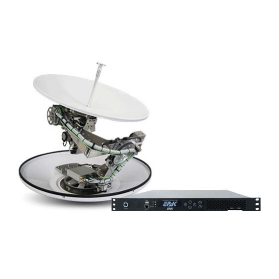
- Page 1 Installation and User Manual Maritime VSAT systems DSi6Ku Pro DSi6Ku Pro DSi9Ku Pro DSi13Ku Pro Page 1/32 Doc ID 0304 03.07.20...
- Page 2 The serial number (standard format: 090UC.10.1843.0000) will be required for all service requests regarding this product. You can find the serial number of your EPAK VSAT system both engraved on the chassis of the antenna (Figure 1) and on the delivery note sent to you with the system.
-
Page 3: Table Of Contents
Table of Contents Introduction ..............................5 Safety Recommendations & Precautions ......................6 Microwave radiation hazard ........................6 Radar interference ............................6 Exposure to rain / moisture ......................... 6 Necessity of grounding the equipment ....................... 6 Power supply .............................. 7 Maintain ambient temperature for IDU ....................... 7 Maintain ambient temperature for ODU ...................... -
Page 4: Introduction
Introduction Intended readers This is an installation and user manual for the EPAK VSAT systems PRO Series, intended for installers of the system and service personnel. Personnel installing or servicing the system must be properly trained and authorized by EPAK. It is important that you observe all safety requirements listed in the beginning of this manual, and install the system according to the guidelines in this manual. -
Page 5: Safety Recommendations & Precautions
Safety Recommendations & Precautions Microwave radiation hazard igure 2.1: Microwave radiation safety distance Ensure that all personnel stay outside of the safety distance during antenna operation. During operation the antenna uses high-powered BUCs in order to establish a two-way communication with the satellite. The resulting radiation is hazardous. Note the following points for your safety. -
Page 6: Power Supply
The ACU requires 90-264V AC @ 47-63 Hz Input voltage & frequency. The ACU then supplies DC power to the Antenna. Use of an online UPS is mandatory for EPAK systems, otherwise the warranty becomes void. For more details see 4.8. -
Page 7: System Components List
DSi13 : 12 mounting screws VSAT manual VSAT manual for easy operation & configuration of the system. Up-to-date documents are available for download on www.epak.de/en. Add-ons (Optionally supplied by EPAK) Component Description Satellite Modem Supported modem types: iDirect modems - Evolution, Velocity platform •... -
Page 8: Installation Procedure
Vessel Management Router Network monitoring & control • Traffic prioritization • Hotspot management • Managing Crew calling services • Web Filtering • PBX equipment Handling SIP service for making low cost Voip calls IP Telephones For making VoIP calls Online UPS system Cables 2x Double shielded coax cable (ECOFLEX10 or 15) with N-Plugs 2x Double shielded coax cable (RG6) with F and TNC-plugs... -
Page 9: Radar Interferences
Bad location: in such a situation it is Better: by setting the antenna to one Best location: if possible, place the very likely to incur a wide blind spot. end of the ship, the obstacle can be antenna on top of the boat. overcome. -
Page 10: Planning The Cable Paths
If you're in charge of laying the cables, make sure it is done in accordance with the following rules: Use suitable coax cables: double shielded EcoFlex 10 or 15 is recommended. EPAK warranty does • not cover decreased performance due to improper wiring. - Page 11 Dimensions and drilling patterns Click for full view or refer to page 29 Figure 4.3: Dimensions 60 cm antenna dome (front and bottom) Click for full view or refer to page 30 Figure 4.4: Dimensions 90 cm antenna dome (front and bottom) Click for full view or refer to page 31...
-
Page 12: Installing The Antenna
Installing the Antenna Before installing the antenna, please take the following precautions: Caution: The radome has to be properly fixed on the antenna before installing it on the platform. • For safety during transport, the antenna has locks for the movement in skew, elevation, roll and •... -
Page 13: Installing The Indoor Unit
Step 1 Release the skew movement by turning the handle into upward position as shown in the figure. Step 2 Release the elevation movement by turning the handle to downward position as shown below. Step 3 Release the roll movement by turning the handle to the right as shown in the figure below Step 4 Release azimuth movement by... -
Page 14: Power Supply For Vsat System
ACU must be kept clear to allow ventilation. Otherwise, overheating might cause system shutdown. Either the UPS is provided by EPAK or a compatible UPS (on-line/double-conversion type) has to be • installed by the ship owner for powering the IDU. -
Page 15: System Cable Connections
The ACU has to be connected to 230V • AC 50Hz from a online type UPS, otherwise the warranty on EPAK system will be void. Figure 4.10 Cable connection with drip loop • After the ODU and IDU are installed, proceed to connect the ACU and ODU as follows: The two antenna cables (RX+power and TX) must be connected to the ACU and the ODU. -
Page 16: Operating The Vsat System
ACU's web-interface. The ACU has to be mounted into a standard 19-inch rack. All EPAK VSAT systems provide a web interface for basic monitoring and configuration, which can be accessed by connecting to any one of its LAN interfaces. - Page 17 L: Antenna RX R: Mains Power Input and Switch IDB Connector (RJ45) Use these ports to connect several EPAK devices together (e.g. DivKit, second ACU, heating controller). Use only if you are instructed to do so by a technician. Serial Connector RS232 (RJ45) Connect this port to a RS232 device which should be controlled by the ACU.
- Page 18 Access to the Webinterface: Connect a computer to this port if you need to access the ACU via network. Access: Lan2 with ethernet cable Address: 192.168.2.254 Username: admin Password: (empty) Please contact itservice@epak.de for remote support. Page 18/32 Doc ID 0304 03.07.20...
-
Page 19: Accessing The Acu
Accessing the ACU All EPAK VSAT systems provide a web interface for basic monitoring and configuration. The connection interface is provided by any PC connected to the ACU (through a local network connection). Users can simply use their web browser to access this functionality without additional software installation. -
Page 20: Status -> Network
Display: Here you see the current SNR in dB, the TX state, the satellite position, the current antenna state, the current heading (from external NMEA or if its not connected, from the GPS data), the online status and the orbit position. -
Page 21: Status -> System
5.2.2 Status -> System This page is useful to monitor functionality of the system. It shows the graphs of CPU load, the memory statistics, the system temperature and the used disk space. The graphs show data over a day, over the last week and over the last month. -
Page 22: System Configuration
OpenAMIP configuration if your modem supports this protocol. If you do not find the correct modem type in this list, please contact EPAK for more details. If your current modem has a traffic VLAN IP address, please fill in the details for this as well. - Page 23 To view the current firewall configuration, please click on “Firewall ” on the left hand side of the page. Here you can see the firewall rules, policy, zones and interfaces. Currently these rules can only be viewed and not edited. To view the current network routing, click on “Routing”...
-
Page 24: Configuration -> Antenna
“✖” button. 5.3.5 Configuration -> Update This section is used for updating the antenna firmware or updating the ACU Software version. To use this section, please contact the EPAK IT team. Account Details Page 24/32 Doc ID 0304 03.07.20... -
Page 25: Service Activation
Maintenance The EPAK VSAT system is easy to maintain. The following instructions are sufficient to sustain an optimal performance of the antenna unit: • Clean the radome once a month using fresh water and a mild detergent to remove dirt and salt deposits. -
Page 26: Hardware Configuration
/ dealer. Hardware configuration The EPAK antenna can be paired with various types of hardware to accommodate your requirements for internet speed and connectivity. Please check this section for more information on the types of BUCs and LNBs used. -
Page 27: Datasheets
2x Double shielded coax cable (RG6) with F and TNC-plugs 1x Ethernet patch with RJ45 plugs ACU to Network Ethernet patch with RJ45 plugs Antenna DSi6 Ku Pro DSi9 Ku Pro DSi13 Ku Pro https://www.epak.de/en/support/download-area Please refer to datasheets, available on our website. Page 27/32 Doc ID 0304 03.07.20... -
Page 28: Glossary
Skew is the tilt of the LNB in order to align the planes of polarization of antenna & the satellite. Uninterrupted Power Supply. Online type is recommended for EPAK systems. The ratio of signal power to noise power, expressed in dB. The higher the SNR, better the signal quality. - Page 29 Drilling Pattern DSi6 Figure 8.1 Drilling Pattern 60cm VSAT Page 29/32 Doc ID 0304 03.07.20...
- Page 30 Drilling Pattern DSi9 Figure 8.2 Drilling Pattern 90cm VSAT Page 30/32 Doc ID 0304 03.07.20...
- Page 31 Drilling Pattern DSi13 Figure 8.3: Drilling Pattern 130cm VSAT Page 31/32 Doc ID 0304 03.07.20...
- Page 32 Picture Index Figure 1: Antenna label with serial number....................... 2 Figure 2.1: Microwave radiation safety distance....................5 Figure 4.1: Finding the best location for the antenna..................9 Figure 4.2: Minimum safe distance from radar....................9 Figure 4.3: Dimensions 60 cm antenna dome (front and bottom)..............11 Figure 4.4: Dimensions 90 cm antenna dome (front and bottom)..............11 Figure 4.5: Dimensions 130 cm antenna dome (front and bottom)..............11 Figure 4.6: Position of transport locks......................
Need help?
Do you have a question about the DSi6Ku Pro and is the answer not in the manual?
Questions and answers