
Subscribe to Our Youtube Channel
Related Manuals for Wallbe LEO


Summary of Contents for Wallbe LEO
- Page 1 Driving eMobility wallbe Charging station ® Wallbox INSTALLATION MANUAL 211510-a 09/2020...
-
Page 2: Table Of Contents
Installation Manual TABLE OF CONTENTS 1 General information....................................3 1.1 Introduction.........................................3 1.2 Intended use......................................3 2 Safety.........................................4 2.1 Safety instructions....................................4 2.2 Installation and tests....................................5 2.3 Protective devices....................................7 2.4 Operator control elements..................................7 3 Installation....................................8 3.1 Prerequisites................................8 3.2 Scope of supply/Enclosed accessories..............................8 3.3 Mounting on the wall.....................................9 3.4 Mounting on a column....................................9 3.5 Electical connection....................................10 3.6 Commissioning................................11... -
Page 3: General Information
Thank you for choosing one of our products. The char- qualified electricians who have been correspondingly ging stations of wallbe® offer convenient, safe and authorized by the operator. standard compliant charging according to the standard The qualified electricians must have read and unders- IEC 61851-1, charging mode 3. -
Page 4: Safety
(ICD) wish to conduct activities • charging system and vehicle. on charging systems and their devices in the inten- ded manner, wallbe® is not in a position to make any Safety devices on the charging system statement regarding the suitability of such medial de- •... -
Page 5: Installation And Tests
Installation Manual • AC residual-current detection not clean or wash the vehicle with a high pressure cleaner because the plug-in connection is not sealed The charging system is equipped with integrated AC against pressurized water. residual-current detection as a convenience function. In case of malfunctions or failure of the charging sys- This residual-current detection switches off the char- ging system, at the latest, if there is a residual current... - Page 6 Installation Manual power supply line to the charging system in the build- to a test adapter for vehicle simulation in accordance ing‘s electrical cabinet. The value must not exceed 1 with EN 61581-1. The measurements must be carried MΩ. out with the adapter in the C mode. Carry out the mea- surements on the measuring sockets of the test adap- Note: The Wallbox has a surge protector.
-
Page 7: Protective Devices
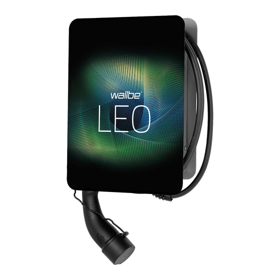
Installation Manual 2.3 Protective devices 2.4 Operator control elements The following figure shows the wallbe® LEO charging The following components are protective devices: station. Depending on the variant ordered, the optical appearance differs from the figure. Figure 1: Charging system... -
Page 8: Installation
Installation Manual 3 INSTALLATION • Disconnect the charging system from the power supply by switching off the respective circuit brea- ker in the building. 3.1 Prerequisites • The Wallbox may only be operated when mounted vertically. • Disable the charging system using the optional ex- ternal blocking device. -
Page 9: Mounting On The Wall
(slotted holes, Fig. 4). 5. Screw the third fastening screw into the lower hole. 6. Tighten the three fastening screws (approx.12 Nm). Figure 3: Overview of wallbe® LEO 3.4 Mounting on a column Prerequisites 1. Hang the mounting plate of the Wallbox (Fig. 4) on the three stud bolts of the column (Fig. -
Page 10: Electical Connection
3.5 Electrical connection Figure 7: Terminal clamps of the power supply unit Caution - Heed the terminal sequence. When clamping Figure 6: wallbe® LEO, opened electronics housing the connecting line, heed the sequence of the termi- Prerequisites nals. PE, L3, L2, L1, N. -
Page 11: Commissioning
The rotary switch (Fig. 8/1) is used to set the charging current from 6 to 16 A. 6 A (default setting, delivery state) Figure 10: wallbe® LEO 10 A 1 Pushbutton/LED combination 12 A 2 Nameplate 14 A 1. -
Page 12: Technical Data
Installation Manual 4 TECHNICAL DATA Designation Technical specifications Regulations IEC 61851-1 Charging capacity type 3 up to 11 kW Nominal voltage 230 V / 400 V / 1/3 AC Nominal current up to 16 A adjustable from 6 A to 16 A in 2 A increments Nominal frequency 50 Hz... - Page 16 This document may not be copied in whole or in part or reproduced in any form Paderborner Straße 76 or form without the written permission of wallbe GmbH. All illustrations in this 33189 Schlangen manual are only examples and may differ from the delivered product. All infor- Tel.: +49 (0) 5252 98892-00...
Need help?
Do you have a question about the LEO and is the answer not in the manual?
Questions and answers