
Related Manuals for Caen V812

Summary of Contents for Caen V812
- Page 1 Technical Information Manual Revision n. 4 20 April 2009 MOD. V 812 series 16 CH. CONSTANT FRACTION DISCRIMINATORS NPO: 00101/97:V812x.MUTx/04...
- Page 2 User. It is strongly recommended to read thoroughly the CAEN User's Manual before any kind of operation. CAEN reserves the right to change partially or entirely the contents of this Manual at any time and without giving any notice. Disposal of the Product The product must never be dumped in the Municipal Waste.
-
Page 3: Table Of Contents
Document type: Title: Revision date: Revision: User's Manual (MUT) Mod. V812 16 Channel Constant Fraction Discriminator 20/04/2009 TABLE OF CONTENTS GENERAL DESCRIPTION............................5 1.1..........................5 UNCTIONAL DESCRIPTION 1.2...............................7 LOCK DIAGRAM 1.3........................8 ECHNICAL SPECIFICATION TABLE TECHNICAL SPECIFICATIONS .........................9 2.1...............................9 ACKAGING 2.2. - Page 4 Document type: Title: Revision date: Revision: User's Manual (MUT) Mod. V812 16 Channel Constant Fraction Discriminator 20/04/2009 4.7..........................20 ETTING THE THRESHOLD 4.8........................20 ETTING THE OUTPUT PULSE WIDTH 4.9..........................21 ETTING THE 4.10............................21 URRENT UM SIGNAL 4.11............................22...
-
Page 5: General Description
1.1. Functional description The CAEN Model V812 is a 16 CHANNEL CONSTANT FRACTION DISCRIMINATOR housed in a single width VME module. The module accepts 16 negative inputs and produces 16 differential ECL outputs with a fan-out of two on four front panel flat cable connectors (a functional block diagram is shown in Fig. -
Page 6: Fig . 1.1: Model Type Label ( Example V812 B)
MAY 5th 2002 RIF N. DATE Fig. 1.1: Model type label (example V812 B) A label on the printed board soldering side indicates the module’s version (see Fig 1.1). The version with the PAUX connector requires the V430 backplane. Available exclusively on request... -
Page 7: Block Diagram
Document type: Title: Revision date: Revision: User's Manual (MUT) Mod. V812 16 Channel Constant Fraction Discriminator 20/04/2009 1.2. Block diagram DACs,TEST, INHIBIT W LOGIC ......test 8 bit 8 bit 8 bit 8 bit inhibit 8 bit ....ch.0 ch.1 ch14 ch.15... -
Page 8: Technical Specification Table
Document type: Title: Revision date: Revision: User's Manual (MUT) Mod. V812 16 Channel Constant Fraction Discriminator 20/04/2009 1.3. Technical specification table Table 1.2: Technical specification table Packaging 6U-high, 1U-wide VME unit Power requirements Refer to § 2.2 16 inputs (negative polarity, 50 Ω impedance) -
Page 9: Technical Specifications
Mod. V812 16 Channel Constant Fraction Discriminator 20/04/2009 Technical Specifications 2.1. Packaging The Mod. V812 is housed in a 6U-high 1U-wide VME unit. 2.2. Power requirements The power requirements of the Mod. V812 are as follows: Table 2.1: Power requirements... -
Page 10: Front Panel
Document type: Title: Revision date: Revision: User's Manual (MUT) Mod. V812 16 Channel Constant Fraction Discriminator 20/04/2009 2.3. Front Panel Mod. V812 Σ 16 CH 16 CH Fig. 2.1: Front Panel NPO: Filename: Number of pages: Page: 00101/97:V812x.MUTx/04 V812_REV4.DOC... -
Page 11: External Connectors
Document type: Title: Revision date: Revision: User's Manual (MUT) Mod. V812 16 Channel Constant Fraction Discriminator 20/04/2009 2.4. External connectors The location of the connectors is shown in Fig. 2.1. Their function and electromechanical specifications are listed in the following subsections. -
Page 12: Other Components
Function: they allow to set the Delay. The Delay values range up to 20 ns with 4 ns steps (please refer to Fig. 2.3 for the jumpers location on the V812 board). Factory setting is 20 ns. Optionally is also available 5ns full scale with 1ns steps, 50ns full scale with 10ns steps and 100ns full scale with 20ns steps. -
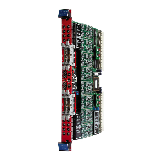
Page 13: Fig . 2.2: Components Location
Document type: Title: Revision date: Revision: User's Manual (MUT) Mod. V812 16 Channel Constant Fraction Discriminator 20/04/2009 Base address bit <23 ... 20> Rotary switches for Base Address selection Base address bit <19 ... 16> Channels 8 to 14 Discrim inator Ch. -
Page 14: Fig . 2.3: Jumpers Location
Document type: Title: Revision date: Revision: User's Manual (MUT) Mod. V812 16 Channel Constant Fraction Discriminator 20/04/2009 piggy back m in delay m ax delay board JP 2 CH. 14 JP 3 CH. 15 VME P1 connector JP 4 CH. 12 JP 5 CH. -
Page 15: Vme Interface
VME Interface 3.1. Addressing Capability The V812 module works in A24/A32 mode. This implies that the module’s address must be specified in a field of 24 or 32 bits. The address modifiers codes recognized by the module are: AM = %39... -
Page 16: Discriminator Thresholds
Title: Revision date: Revision: User's Manual (MUT) Mod. V812 16 Channel Constant Fraction Discriminator 20/04/2009 3.2. Discriminator thresholds (Base address + %00 to %1E write only) These registers contain the discriminator threshold values on 8 bit words. The threshold values... -
Page 17: Dead Time C H
Title: Revision date: Revision: User's Manual (MUT) Mod. V812 16 Channel Constant Fraction Discriminator 20/04/2009 3.5. Dead Time Ch. 0 to 7 (Base address + %44 write only) This register is used to select the Dead Time value common to all channels from 0 to 7. This command allows to select on 8 bit (set values: 0 to 255) the Dead Time value between 150 ns and 2 μs. -
Page 18: Fig . 3.2: Module Identifier Words
Fig. 3.2: Module Identifier Words At the address Base + %FA the two particular bytes allow the automatic localization of the module. For the Mod. V812 the word at the address Base + %FC has the following configuration: Manufacturer N° 000010 b... -
Page 19: Principles Of Operation
§ 4.1. The Delay values range up to 20 ns with a step of 4 ns; in order to gain access to the jumpers it’s necessary to unplug the relevant piggy back board (see for the jumpers location on the V812 board). Factory setting is 20 ns. The fraction is a fixed 20% value. 4.4. Enabling/Disabling the channels The User can enable or disable each of the 16 channels via VME by performing a VME write access at Base address + %4A. -
Page 20: Test, Veto And Or Signals
4.7. Setting the threshold For each channel of the V812 the discriminator threshold is set up via an 8 bit DAC. The threshold values can be programmed in a range from -1 mV to -255 mV with -1 mV steps (set values: 1 to 255). -
Page 21: Setting The Dead Time
Title: Revision date: Revision: User's Manual (MUT) Mod. V812 16 Channel Constant Fraction Discriminator 20/04/2009 4.9. Setting the Dead Time It is possible via VME to set a Dead Time value in common to a group of 8 channels. This prevents the triggering of the discriminator by unwanted pulses occurring within the Dead Time programmed value. -
Page 22: Majority Setting
Title: Revision date: Revision: User's Manual (MUT) Mod. V812 16 Channel Constant Fraction Discriminator 20/04/2009 4.11. Majority setting Majority output provides a standard NIM signal if the number of channels over threshold exceeds the programmed majority level (MAJLEV). MAJLEV can be programmed between 1 and 16, writing a proper value (MAJTHR) in the Majority threshold register (see §... -
Page 23: Fig . 4.2: Example Of Three Daisy Chained V812
Number of Module’s active Channels ACTIVE NON Active ACTIVE Majority Output (5 > MAJLEV) (4 < MAJLEV) (5+4+3 > MAJLEV) Fig. 4.2: Example of three daisy chained V812 NPO: Filename: Number of pages: Page: 00101/97:V812x.MUTx/04 V812_REV4.DOC...
Need help?
Do you have a question about the V812 and is the answer not in the manual?
Questions and answers