
Related Manuals for J&M Nitro Gro 6018


Summary of Contents for J&M Nitro Gro 6018
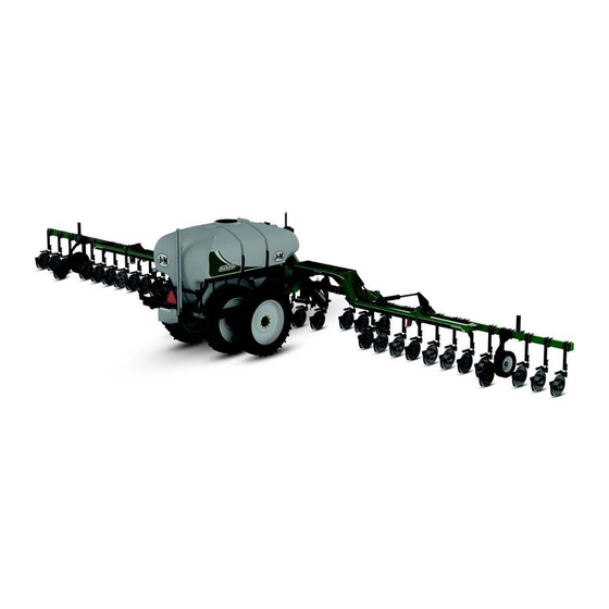
- Page 1 Manual MODEL O P E R A T O R ’ S M A N U A L J&M Manufacturing Co, Inc 284 Railroad Street - P.O. Box 547 | Fort Recovery, OH 45846 | Ph: (419) 375-2376 | Fax: (419) 375-2708 www.jm-inc.com...
-
Page 2: Table Of Contents
Table Of Contents To The Dealer ....................4 Serial Number . - Page 3 Table Of Contents Outside Wing and Connections ................44 Wing End and Wing Prop .
-
Page 4: To The Dealer
To The Dealer TO THE DEALER Read manual instructions and safety rules. Make sure all items on the Dealer’s Pre-Delivery and Delivery Check Lists are completed before releasing equipment to the owner. The dealer must complete the Warranty Registration found on the Dealer Portal website located at dealer.jm-inc.com and return it to J&M Mfg. -
Page 5: Serial Number
Serial Number Serial Number______________________ Model Number_______6018__________ Standard practice when ordering parts or obtaining information from your dealer requires the serial number and model number. Have numbers available before making contact. Dealer Set-Up • Run water into the tank, turn pump on, and check for leaks. Ensure agitation valve is open to allow pump to prime. •... -
Page 6: General Information
General Information TO THE OWNER: The purpose of this manual is to assist you in operating and maintaining your seed tender in a safe manner. Read it carefully. It furnishes information and instructions that will help you achieve years of dependable performance and help maintain safe operating conditions. If this machine is used by an employee or is loaned or rented, make certain that the operator(s), prior to operating: 1. -
Page 7: Safety Rules
Safety Rules ATTENTION! BECOME ALERT! YOUR SAFETY IS INVOLVED! Safety is a primary concern in the design and manufacture of our products. Unfortunately, our efforts to provide safe equipment can be erased by an operator’s single careless act. In addition, hazard control and accident prevention are dependent upon the awareness, concern, judgment, and proper training of personnel involved in the operation, transport, maintenance and storage of equipment. -
Page 8: Bolt Torque Chart
Bolt Torque Chart Always tighten hardware to these values unless a different torque or tightening procedure is listed for specific application. Fasteners must always be replaced with the same grade as specified in the manual parts list. Always use the proper tool for tightening hardware. Make sure fastener threads are clean and you start thread engagement properly. -
Page 9: Specifications
Specifications SPECIFICATIONS 6000 Series Applicators Tank Size 1,850 Gallon Base Width 60’ Ground Clearance 40” Row Spacing* 20”, 22”, 30” Number of Coulters 23, 25, 35, 37 Coulter Style Grove Engineered Products (GEP) or J&M ParaLinkage Fertilizer Delivery Knife or Injection Wing Flex Standard 15°... -
Page 10: Nitrogro Components
NitroGro Components Flow Monitors Down Pressure Relief Valve Toolbar Down Pressure Gauge Hitch Tank Hand Wash Tank Tank Fill Valve Strainer Gauge Wheel Coulter Agitation Valve Hydraulic Pump... -
Page 11: Down Pressure Relief Valve
Flow Monitors Flow monitors allow the operator to see the rate of flow to each coulter through a floating ball inside the transparent inspection tube. Each coulter is connected with a separate supply hose. Down Pressure Relief Valve The down pressure relief valve provides adjustable hydraulic pressure to force the coulters on the wings into the ground while allowing the wing to flex up and down as needed to follow the contour of the ground. -
Page 12: Coulter
Coulter The number of coulters is determined by the number of rows (usually one less or one more). So the number of rows will be even, and the number of coulters will be odd, since you are placing the nitrogen between the rows. For example, a 24 row unit will have either 23 or 25 coulters. -
Page 13: Strainer
Strainer The NitroGro applicator is equipped with a strainer designed to remove dirt and debris from the fertilizer to prevent downstream clogs. Agitation Valve The agitation valve is designed to allow air to escape from the pump so it can easily prime. When you’re running in the field, a little liquid runs through the agitation valve back to the tank. -
Page 14: Pre-Operation Checklist
Pre-Operation Checklist Preparing the NitroGro Applicator: IMPORTANT - Before putting the applicator into operation, check the machine for damaged or worn parts and replace as necessary. Only use a tractor with sufficient power and weight to operate the applicator. For 24 rows, use a minimum of 275 hp tractor and for 36 rows use a minimum of 410 hp tractor. -
Page 15: Hitching And Unhitching The Applicator
Hitching and Unhitching the Applicator Connect the applicator to the tow vehicle using a hitch pin and make sure a retaining pin is secured in the hitch pin. Always attach the safety chains to the applicator and the tow vehicle. WARNING –... -
Page 16: Folding & Unfolding
Folding & Unfolding Unfolding Folding Toolbar Completely Up Toolbar Completely Up (Down Pressure Circuit - Green Taped Hoses) (Down Pressure Circuit - Green Taped Hoses) Flip Toolbar In (Toolbar Flip Circuit - Red Taped Hoses) Main Toolbar Forward and Allow Locks to Fully Engage. Hold hydraulics for 5 seconds once wings fold completely forward. -
Page 17: Adjusting The Field Depth
Adjusting the Field Depth • Set the center section of coulters first. Spacers are included with the toolbar cylinders. Add or remove spacers until the center section is positioned at the appropriate depth. Lower the unit until the lift cylinders bottom out on the stroke control spacers. -
Page 18: Operation
Operation Hook tractor to NitroGro and adjust hitch so that frame on applicator is level or tilting forward slightly. Connect hydraulic lines. See “Connecting the Hydraulic Hoses” on page 15. Unfold the unit. See “Folding & Unfolding” on page 16. Lower the unit until the lift cylinders bottom out on the stroke control spacers. -
Page 19: Flow Monitor Set Up
Flow Monitor Set Up The NitroGro applicator offers row spacing options of 20”, 22”, or 30”. The unit will be either be set up to or re-apply the outside row (“1 Up”), or skip a row (“1 Down”). Using your row spacing and whether your aplicator is “1 Up” or “1 Down”, refer to the chart below to determine the location and quantity of flow monitors for your applicator. -
Page 20: Injectors - 20" Row Spacing
Injectors - 20” Row Spacing 20 Gallons Per Acre 25 Gallons Per Acre Speed (MPH) #10 Injector (psi) #15 Injector (psi) #20 Injector (psi) #30 Injector (psi) #40 Injector (psi) GPM (per nozzle) 0.34 0.43 0.52 0.60 0.69 0.77 0.86 0.95 1.03 0.43 0.54 0.64 0.75 0.86 0.97 1.07 1.18 1.29 Flow Indicator 1/2"... - Page 21 Injectors - 20” Row Spacing 50 Gallons Per Acre 55 Gallons Per Acre Speed (MPH) #10 Injector (psi) 103 115 104 115 129 #15 Injector (psi) #20 Injector (psi) #30 Injector (psi) #40 Injector (psi) GPM (per nozzle) 0.86 1.07 1.29 1.50 1.72 1.93 2.15 2.36 2.58 0.95 1.18 1.42 1.66 1.89 2.13 2.36 2.60 2.84 Flow Indicator 1/2"...
-
Page 22: Injectors - 22" Row Spacing
Injectors - 22” Row Spacing 15 Gallons Per Acre Speed (MPH) #10 Injector (psi) #15 Injector (psi) #20 Injector (psi) #30 Injector (psi) #40 Injector (psi) GPM (per nozzle) 0.25 0.31 0.38 0.44 0.50 0.57 0.63 0.69 0.75 Flow Indicator Red Glass Level 1.1 1.7 Flow Indicator 1/2"... - Page 23 Injectors - 22” Row Spacing 40 Gallons Per Acre 45 Gallons Per Acre Speed (MPH) #10 Injector (psi) 102 114 #15 Injector (psi) #20 Injector (psi) #30 Injector (psi) #40 Injector (psi) GPM (per nozzle) 0.76 0.95 1.14 1.32 1.51 1.70 1.89 2.08 2.27 0.85 1.06 1.28 1.49 1.70 1.92 2.13 2.34 2.55 Flow Indicator 1/2"...
-
Page 24: Injectors - 30" Row Spacing
Injectors - 30” Row Spacing 15 Gallons Per Acre Speed (MPH) #10 Injector (psi) #15 Injector (psi) #20 Injector (psi) #30 Injector (psi) #40 Injector (psi) GPM (per nozzle) 0.34 0.43 0.51 0.60 0.68 0.77 0.86 0.94 1.03 Flow Indicator Red Glass Level Flow Indicator 1/2"... - Page 25 Injectors - 30” Row Spacing 40 Gallons Per Acre 45 Gallons Per Acre Speed (MPH) #10 Injector (psi) 115 128 143 113 132 146 163 #15 Injector (psi) #20 Injector (psi) #30 Injector (psi) #40 Injector (psi) GPM (per nozzle) 1.03 1.29 1.55 1.81 2.06 2.32 2.58 2.84 3.10 1.16 1.45 1.74 2.03 2.32 2.61 2.90 3.19 3.48 Flow Indicator 1/2"...
-
Page 26: Knife - 20" Row Spacing
Knife - 20” Row Spacing 10 Gallons Per Acre 15 Gallons Per Acre Speed (MPH) 0.075 Orifice Pressure (psi) 0.107 Orifice Pressure (psi) 0.132 Orifice Pressure (psi) 0.161 Orifice Pressure (psi) GPM (per nozzle) 0.15 0.19 0.23 0.27 0.30 0.34 0.38 0.42 0.46 0.23 0.29 0.34 0.40 0.46 0.51 0.57 0.63 0.68 Flow Indicator Red Glass Level 0.3 Flow Indicator 1/2"... - Page 27 Knife - 20” Row Spacing 40 Gallons Per Acre 45 Gallons Per Acre Speed (MPH) 0.075 Orifice Pressure (psi) 103 117 131 145 103 119 134 150 165 0.107 Orifice Pressure (psi) 0.132 Orifice Pressure (psi) 0.161 Orifice Pressure (psi) GPM (per nozzle) 0.61 0.76 0.91 1.07 1.22 1.37 1.52 1.67 1.83 0.68 0.86 1.03 1.20 1.37 1.54 1.71 1.88 2.05 Flow Indicator 1/2"...
-
Page 28: Knife - 22" Row Spacing
Knife - 22” Row Spacing 10 Gallons Per Acre 15 Gallons Per Acre Speed (MPH) 0.075 Orifice Pressure (psi) 0.107 Orifice Pressure (psi) 0.132 Orifice Pressure (psi) 0.161 Orifice Pressure (psi) GPM (per nozzle) 0.17 0.21 0.25 0.29 0.33 0.38 0.42 0.46 0.50 0.25 0.31 0.38 0.44 0.50 0.57 0.63 0.69 0.75 Flow Indicator Red Glass Level Flow Indicator 1/2"... - Page 29 Knife - 22” Row Spacing 40 Gallons Per Acre 45 Gallons Per Acre Speed (MPH) 0.075 Orifice Pressure (psi) 100 116 131 146 161 116 133 150 167 184 0.107 Orifice Pressure (psi) 0.132 Orifice Pressure (psi) 0.161 Orifice Pressure (psi) GPM (per nozzle) 0.67 0.84 1.00 1.17 1.34 1.51 1.67 1.84 2.01 0.75 0.94 1.13 1.32 1.51 1.70 1.88 2.07 2.26 Flow Indicator 1/2"...
-
Page 30: Knife - 30" Row Spacing
Knife - 30” Row Spacing 10 Gallons Per Acre 15 Gallons Per Acre Speed (MPH) 0.075 Orifice Pressure (psi) 0.107 Orifice Pressure (psi) 0.132 Orifice Pressure (psi) 0.161 Orifice Pressure (psi) GPM (per nozzle) 0.23 0.29 0.34 0.40 0.46 0.51 0.57 0.63 0.68 0.34 0.43 0.51 0.60 0.68 0.77 0.86 0.94 1.03 Flow Indicator Red Glass Level 0.9 Flow Indicator 1/2"... - Page 31 Knife - 30” Row Spacing 40 Gallons Per Acre 45 Gallons Per Acre Speed (MPH) 0.075 Orifice Pressure (psi) 103 124 145 165 186 207 228 119 142 165 189 212 235 259 0.107 Orifice Pressure (psi) 102 114 0.132 Orifice Pressure (psi) 0.161 Orifice Pressure (psi) GPM (per nozzle) 0.91 1.14 1.37 1.60 1.83 2.05 2.28 2.51 2.74 1.03 1.28 1.54 1.80 2.05 2.31 2.57 2.83 3.08...
-
Page 32: Quick Start For Raven 450 Controller
Quick Start for Raven 450 Controller Initial Console Programming • Select the unit of measurement by pressing the CE button until the desired selection appears in the display and press “ENTER” NOTE - The unit of measurement for the United States is Volume per Acre. •... -
Page 33: Service
Service To prolong the life of your NitroGro applicator, perform the following on a regular basis: 1. Every 10 hours, ensure the toolbar raise switch valve is functioning properly. Switch should return to the closed position when not triggered. The pictures below show the valve in the closed and open positions. If the switch does not return to the closed position, gently tap the plunger (circled in the pictures below) down with a hammer. -
Page 34: Storage
Storage To prolong the life of your NitroGro applicator, hook the applicator to a tractor, unfold it, and perform the following before placing the implement in storage: 1. Pressure wash the NitroGro applicator to remove dirt and debris that may cause rusting. 2. -
Page 35: Troubleshooting
Troubleshooting WARNING - MAKE SURE THAT ALL POWER IS SHUT OFF BEFORE SERVICING THE APPLICATOR. MAINTENANCE AND REPAIR SERVICE WORK TO BE PERFORMED BY QUALIFIED SERVICEMEN ONLY. Trouble Possible Cause Possible Remedy Outside tool bar wing creeps Counterbalance valve is too loose Tighten counterbalance valve. -
Page 36: Decals
Decals ATTENTION! BECOME ALERT! YOUR SAFETY IS INVOLVED! Replace Immediately If Damaged or Missing MAKE SURE LOCKS COULTER BEARING LUBRICATION 2 pumps of good quailty LS EP2 severe duty, ARE FULLY high shock load, lithium based grease every ENGAGED 50 hrs of operation to every coulter bearing. DO NOT OVER GREASE AND APPLY CONSTANT DAMAGE TO SEALS WILL OCCUR! - Page 37 Decals WARNING WARNING USE CYLINDER STOPS TO CONTROL KNIFE DEPTH IN FIELD USE CYLINDER STOPS TO CONTROL Failure to due so will result in hydraulic damage. JM0035890 KNIFE DEPTH IN FIELD Failure to due so will result in hydraulic damage. JM0035890 WARNING PINCH POINT...
-
Page 38: Hitch
Hitch Description Part No. 1 1”-8 Gr5 Z Centerlock Hex Nut JM0002149 2 CTD Perfect HItch (Circular Hole) JM0038515 3 1”-8 x 6-1/2” Gr5 Z Hex Bolt JM0014192 4 40k Lb Safety Chain JM0029261 Jack Assembly Description Part No. Jack Mounting Bracket (NitroGro) JM0031545 1”-8 Gr5 Z Centerlock Hex Nut JM0002149 1”-8 x 8”... -
Page 39: Hub And Spindle Assembly
Hub and Spindle Assembly Description Part No. W-881 Hub Assembly Complete with 3/4” Studs and Nuts (Less Seal and Spindle) JM0050402 1”-8 Gr5 Z Centerlock Hex Nut JM0002149 1”-8 x 7” Gr5 Z Hex Bolt JM0016689 Spindle, 4-1/2” x 20-1/4” for Walking Tandem Dual Wheel or Fully Adjustable Axle (281900S) JM0019937 Seal (4-1/4”... -
Page 40: Gauge Wheel Assembly
Gauge Wheel Assembly Description Part No. 5/8”-11 x 7-1/8” x 8-11/16” Square U-Bolt JM0020901 5/8”-11 Gr5 Z SF Hex Nut JM0002151 5/8”-11 Gr5 Z Centerlock Hex Nut JM0002146 Gauge Wheel Mounting Plate (6000 Series) JM0047342 5/8”-11 x 4-1/2” Gr5 Z SF Hex Bolt JM0047938 Dust Cap, 6-10 Ton (103969) JM0026567... -
Page 41: Toolbar
Toolbar Description Part No. 1 Stub Wing Weldment JM0046687 2 Toolbar Center Section NitroGro 7000 JM0047104 3 Stub Wing Main Link Weldment JM0047263 4 1” x 3-1/2” Clevis Pin with Cotter Pins JM0001817 5 Stub Wing Small Linkage JM0047264 6 1-1/4” ID x 1-1/2” OD x 2” Long Sleeve Composite Bushing JM0021957 7 1/4”-20 x 2-1/2”... -
Page 42: Inside Wing And Connections
Inside Wing and Connections 11 12 Description Part No. 1/2”-13 x 4” Hex Bolt JM0048014 11-1/4” Clevis Pin (2-1/2” Diameter) JM0046032 1/2”-13 Gr5 Z Centerlock Hex Nut JM0001511 Middle Wing Weldment (Driver’s Side) (6018, 6026) JM0047901 Middle Wing Weldment (Passenger’s Side) (6018, 6026) JM0045028 11-1/4”... -
Page 43: Middle Wing And Connections
Middle Wing and Connections Description Part No. 1-3/4” ID x 2” OD x 1-1/2” Sleeve Composite Bearing JM0030328 9-1/4” Clevis Pin (1-3/4” Diameter) JM0046030 1/2”-13 Gr5 Z Centerlock Hex Nut JM0001511 1/2”-13 x 3” Gr5 Z Hex Bolt JM0016678 Middle Wing Weldment JM0045238 #10-24 x 13/16”... -
Page 44: Outside Wing And Connections
Outside Wing and Connections Description Part No. Cotter Pin (for 1” x 3-2/5” Clevis Pin) JM0003064 1” x 3-2/5” Clevis Pin JM0001816 Long Fold Straight Auger Master Link Weldment JM0046033 1/2”-13 Gr5 Z SF Hex Nut JM0002153 1/2”-11 x 1-3/4” Gr5 Z SF Hex Bolt JM0047937 1-3/4”... -
Page 45: Wing End And Wing Prop
Wing End and Wing Prop Description Part No. 1 6” x 1-7/8” Auger Rest Triangle Pad JM0037644 2 3/8”-16 x 1” Gr5 Z SF Hex Bolt JM0002092 3 3/8”-16 Gr5 Z SF Hex Nut JM0002152 4 2600 Gallon Tank Wing Prop JM0047490 5 3/8”-16 x 1-1/2”... -
Page 46: Walking Dual Wheel Assembly
Walking Dual Wheel Assembly Description Part No. 1”-8 Gr2 Z Centerlock Hex Nut JM0002149 1”-8 x 3” Gr5 Z Hex Bolt JM0016686 3/4”-10 Gr2 Z Centerlock Hex Nut JM0002147 3-3/4” x 17-1/2” Pivot Pin (334PP) JM0019928 3/4”-10 x 5-1/2” Gr5 Z Hex Bolt JM0015522 3-3/4”... -
Page 47: Tank
Tank Description Part No. Applicator Poly Tank Baffle - Clamp for Center Pillar JM0047726 1850 Gallon Tank Center Pillar Baffle 73-11/16” JM0050336 Applicator Poly Tank Baffle - Large Lower Baffle JM0046874 Applicator Poly Tank Baffle - Clamp for Baffle JM0047722 Applicator Poly Tank Baffle - Small Baffle JM0046873 Applicator Poly Tank Baffle - Pillar Foot... -
Page 48: Tank Supports
Tank Supports 11 10... -
Page 49: Tank Strap Down
Tank Supports Description Part No. Side Tank Support Tube Weldment JM0046878 Tank Support Rib Weldment (37-7/8” Height) JM0046594 Front Tank Support Tube Weldment JM0046875 Tank Support Rib Weldment (33-5/32” Height) JM0046591 Base Frame Weldment - NitroGro JM0053865 Front Tank Support JM0046600 Tank Support Tube Weldment JM0047816... -
Page 50: Hydraulic 150 Ace Pump And Manifold
Hydraulic 150 ACE Pump and Manifold Description Part No. T-Bolt Hose Clamp 2” Hose, 2-5/16” Min OD JM0035247 Manifold Gasket for M200 Fittings JM0021145 Manifold Y Strainer - M200 Manifold Flange, 30 Mesh JM0033803 M200 Manifold Flange x M200 Manifold Flange x M100 Manifold Flange; Tee JM0035116 2”... -
Page 51: Hydraulic 750 Ace Pump And Manifold
Hydraulic 750 ACE Pump and Manifold Description Part No. T-Bolt Hose Clamp 2” Hose, 2-5/16” Min OD JM0035247 Manifold Flange Clamp for M200 Fittings JM0035251 M200 Manifold Flange x M200 Manifold Flange x M100 Manifold Flange; Tee JM0035116 2” Full Port Manifold x 2” Manifold Flange Reducer Coupling JM0035131 Manifold Gasket for M220 Fittings JM0035278... -
Page 52: Raven Manifold
Raven Manifold Description Part No. T-Bolt Hose Clamp 2” Hose, 2-5/16” Min OD JM0035247 2” Hose Barb x M200 Manifold Flange; Straight JM0033796 M200 Manifold Flange x M200 Manifold Flange x M100 Manifold Flange; Tee JM0035116 Manifold Gasket for M200 Fittings JM0021145 2”... -
Page 53: Parallel Linkage For Toolbar Height Adjustment
Parallel Linkage for Toolbar Height Adjustment Description Part No. 1/2”-13 Gr5 Z Centerlock Hex Nut JM0001511 11-1/4” Clevis Pin (1-3/4” Diameter) JM0045307 1/2”-13 x 3” Gr5 Z Hex Bolt JM0016678 5/8”-11 Gr5 Z Centerlock Hex Nut JM0002146 5/8”-11 x 2” Gr8 Z Hex Bolt JM0001771 3/8”-16 x 1-1/4”... -
Page 54: Hand Wash Tank
Hand Wash Tank Description Part No. 9 Gallon Safety/Fresh Water Tank JM0030587 3/4” NPT PVC Threaded Plug Schedule 40 (NitroGro) JM0037251 Drum Faucet - 3/4” NPT JM0039066 1/4”-20 x 3/4” Gr5 Z Hex Bolt JM0001507 Check Valve Description Part No. 1 Diaphragm Check Valve 3/8”... -
Page 55: Slow Moving Vehicle Sign
Slow Moving Vehicle Sign Description Part No. 1 1/4”-20 Gr5 Z SF Hex Nut JM0001630 2 Slow Moving Vehicle Sign JM0001616 3 1/4”-20 x 3/4” Gr5 Z Hex Bolt JM0001507 Coulter Mounts Description Part No. 1 Forward Offset Coulter Mount Weldment (NitroGro 6000 Series) JM0047336 2 Right Offset Coulter Mount Weldment (NitroGro 6000 Series) JM0047869 3 Standard Coulter Mount Weldment (NitroGro 6000 Series) -
Page 56: Coulter Depth Control
Coulter Depth Control Description Part No. 1 20” Straight Coulter Blade with Ripple JM0031269 1 20” Wavy Coulter Blade (5/8” Wave) JM0038506 1 20” Wavy Coulter Blade (1-1/8” Wave) JM0055196 2 GC5000 Depth Control Spool JM0031281 3 Dust Cap Keeper for GEP Coulter JM0038391 4 1/2”... -
Page 57: Coulter Injector Assembly
Coulter Injector Assembly Description Part No. 1/2”-13 SS Nylon Locking Hex Jam Nut JM0041792 1/2”-13 SS Hex Jam Nut JM0041791 3/8” Hose Barb x 1/4” Male NPT SS JM0036419 3/8” Hose Clamp SS JM0039206 1/2”-13 x 3-1/2” SS Hex Bolt JM0041790 3/8”-16 x 1/2”... -
Page 58: Gep Coulter Assembly
GEP Coulter Assembly Description Part No. Shaft 13” - Coulter Mount JM0043034 Cast Coulter Knuckle JM0038257 5/8”-11 x 1” Square Head Bolt JM0037259 Lock Collar for NitroGro JM0038280 3/8” x 3” SS Roll Pin JM0037162 3/4”-10 x 3” Gr5 Z Hex Bolt JM0019201 Spring Rod for GEP Coulter JM0038265... -
Page 59: Gep Coulter Knife Assembly
GEP Coulter Knife Assembly Description Part No. 1 1/2”-13 Gr5 Z Hex Nut JM0002124 2 1/2” Gr2 Z Lock Washer JM0019021 3 1/2” ID, 1-3/8” OD Z Flat Washer JM0003082 4 Coulter Arm for GEP Coulter JM0038397 5 Knife Bracket for GEP Coulter JM0038279 6 3/8”... -
Page 60: J&M Paralinkage Coulter Rod Assembly
J&M ParaLinkage Coulter Rod Assembly Description Part No. 1 13” Shaft - ParaLinkage Coulter Mount JM0049094 2 3/8” x 2-1/2” SS Spirol Coiled Spring Pin JM0049016 3 ParaLinkage Coulter Mount Washer JM0049034 4 1-1/2” ID x 1-5/8 OD x 1” Length Sleeve Composite Bearing JM0048949 5 ParaLinkage - Main Tube Mount Weldment JM0048936 6 5/16”... -
Page 61: J&M Paralinkage Coulter Assembly
J&M ParaLinkage Coulter Assembly Description Part No. 5/8”-11 GrC Z Distorted Thread Hex Nut JM0054594 5/8” USS Flat Washer JM0003073 ParaLinkage Lower Arm Bushing Pivot JM0051220 1” ID x 1-1/4” OD x 1-1/4” Length Sleeve Composite Bearing JM0051195 5/8”-11 x 6-1/2” Gr5 Z Hex Bolt JM0019979 ParaLinkage - Main Arm Weldment JM0048944... -
Page 62: J&M Paralinkage Coulter Knife Assembly
J&M ParaLinkage Coulter Knife Assembly Description Part No. C050 Wiese Knife JM0031273 1/2”-13 x 2-1/2” Gr5 Z Hex Bolt JM0001648 1/2”-13 Z Gr5 Hex Jam Nut JM0002157 ParaLinkage Coulter Knife/Injector Mount JM0049010 1/2” ID, 1-3/8” OD Z Flat Washer JM0003082 1/2”-13 x 2”... -
Page 63: Flow Monitor
Flow Monitor Description Part No. 3/4” Hose Barb x 3/4” Male NPT; 90 Deg JM0035226 1” Male x 3/4” Female PVC Hex Bushing - Black JM0047864 1” Slip x 1” FIPT PVC - Black JM0047865 1800 Gallon Tank Front Sight Glass Bracket JM0054195 1”... -
Page 64: Hydraulic Pump Circuit Hydraulic Schematic
Fill Valves Description Part No. T-Bolt Hose Clamp 3” Hose, 3-5/16” Min OD JM0035248 3” Manifold Flange x 3” Hose Barb JM0021244 3/8”-16 Gr5 Z SF Hex Nut JM0002152 Manifold Worm Screw Clamp 3” JM0035237 3/8”-16 x 1” Gr5 Z SF Hex Bolt JM0002092 Ball Valve Mount Plate 3”... -
Page 65: Main Wing Fold Circuit Hydraulic Schematic
Main Wing Fold Circuit Hydraulic Schematic Description Part No. 3/8” Male JIC x 3/8” Female JIC Swivel; 90 Degree Elbow JM0010295 3/8” Male JIC x 3/8” Male NPT; Straight JM0037167 Flow Diverter Valve JM0018250 3/8” Male NPT x 3/8” Female NPT Swivel with .062 Orifice (Restrictor) JM0018362 3/8”... -
Page 66: Wing Flip Circuit Hydraulic Schematic
Wing Flip Circuit Hydraulic Schematic 3” x 14” Toolbar Flip Cylinders 4” x 24” 4” x 24” Outside Outside Wing Flip Wing Flip Cylinder Cylinder... -
Page 67: Wing Flip Circuit Hydraulic Schematic
Wing Flip Circuit Hydraulic Schematic Description Part No. 4” Bore, 24” Stroke Welded Hydraulic Cylinder JM0030730 1/2” Male ORB x 1/2” Female NPT Swivel; Straight JM0026804 1/2” Male NPT x 1/2” Male O-Ring Hex Nipple JM0048977 3/8” Male JIC x 3/8” Male ORB; 90 Degree Elbow JM0026121 3/8”... -
Page 68: Down Pressure Circuit Hydraulic Schematic
Down Pressure Circuit Hydraulic Schematic 4” x 8” 4” x 8” Inside Inside Wing Wing Height Height 4” x 12” 4” x 12” Toolbar Toolbar Height Height Adjustment Adjustment 16 17 11... -
Page 69: Down Pressure Circuit Hydraulic Schematic
Down Pressure Circuit Hydraulic Schematic Description Part No. 4” Bore, 8” Stroke Welded Hydraulic Cylinder JM0030757 3/8” Male JIC x 1/2” Male ORB; 90 Degree Elbow JM0037159 3/8” Male JIC x 3/8” Female JIC with .094 Orifice JM0047735 3/8” x 155” Hydraulic Hose 155inch6M3K-6G-6FJX-6G-6FJX JM0049161 3/8”... -
Page 70: Fertilizer Hose Routing
Fertilizer Hose Routing Flow Monitor to Check Valve Boom 5 Boom 1 Boom 4 Boom 3 Check Valve to Knife/Injector Boom 2 30" Row Spacing Flow Monitor to Check Valve Check Valve to Knife/Injector Descrip�on Part No. Descrip�on Part No. Coulter 1 140"... - Page 71 Fertilizer Hose Routing Tank Description Part No. 120” x 3/4” Fertilizer Hose JM0050830 48” x 3/4” Fertilizer Hose JM0050825 36” x 3/4” Fertilizer Hose JM0050824 3” x 60” Fertilizer Suction Hose - 2600 Tank JM0050836 96” x 3/4” Fertilizer Hose JM0050826 60”...
-
Page 72: Raven Scs 450 Liquid Control System
Raven SCS 450 Liquid Control System Description Part No. Raven SCS450 Control Console JM0039335 Raven Console Cable (10’) SCS 440/450 JM0039337 Remote Switch Cable for Implement Engagement - Raven 450 Control JM0050676 Mini Wisker Limit Switch JM0050161 Phoenix GPS Speed Sensor JM0039338 Raven Flow Cable - 6 Boom (12’) - 3 Pin Weather Pack JM0039336... -
Page 73: Iso Liquid Control System
ISO Liquid Control System Description Part No. Raven Cable ISOBUS Hitch to Raven ECU (12’) JM0039341 Raven Cable ISOBUS Hitch to Raven ECU (17’) JM0051018 Remote Switch Cable for Implement Engagement - ISO Control JM0050677 Mini Wisker Limit Switch JM0050161 Raven ISO Single Product Kit JM0039339 Raven Flow Cable - 6 Boom (12’) - 3 Pin Weather Pack... -
Page 74: Lights And Wiring
Lights and Wiring Description Part No. 1 Amber Light (Soil Conditioner, NitroGro) JM0009975 2 Red Light (Soil Conditioner, NitroGro) JM0009976 3 NitroGro 6000-Series Rear Harness JM0055138 4 NitroGro 6000-Series Front Harness JM0055137...
Need help?
Do you have a question about the Nitro Gro 6018 and is the answer not in the manual?
Questions and answers