Advertisement
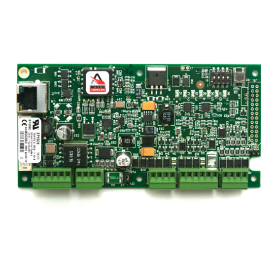
EP1501 Intelligent Controller
with Paired Reader Interface for One Physical Barrier
Installation and Specifications:
1. General:
The EP1501 intelligent controller provides decision making, event reporting and database storage for the
Mercury hardware platform. Two reader interfaces configured as paired or alternate readers provide
control for one physical barrier.
Host communication is via the on-board 10-BaseT/100Base-TX Ethernet port.
Note: For UL compliance, the Power Sourcing Equipment (PSE) such as a PoE enabled network switch
and/or PoE power injectors must be UL Listed under UL294B.
Reader port 1 can accommodate a reader that utilizes TTL (D1/D0, Clock/Data), F/2F, or 2-wire RS-485
device signaling, also provides tri-state LED control, and buzzer control (one wire LED mode only). This
port can also utilize multiple 2-wire RS-485 multi-dropped devices, such as up to two readers or up to
eight remote serial I/O devices.
Reader port 2 can accommodate a reader that utilizes TTL (D1/D0, Clock/Data), or F/2F signaling, also
provides tri-state LED control, and buzzer control (one wire LED mode only). Two Form-C contact relay
outputs may be used for door strike control or alarm signaling. The relay contacts are rated at 2 A @ 30
Vdc, dry contact configuration. Two inputs are provided that may be used for monitoring the door
contact, exit push button or alarm contact.
supervised. The EP1501 requires Power over Ethernet (PoE) or 12 Vdc for power. The EP1501 may be
mounted in a 3-gang switch box; a mounting plate is supplied with the unit, or may be mounted in an
enclosure; the supplied mounting plate has mounting holes that match the MR50 mounting footprint.
2. EP1501 Hardware:
TAMPER
SWITCH
CONNECTION
Ø .125 [Ø3.175]
RESET SWITCH
RELAY K2 LED
RELAY K1 LED
Mercury Security © 2014
2355 MIRA MAR AVE. LONG BEACH, CA 90815-1755, (562)986-9105 FAX (562) 986-9205
.15 [3.81]
2.55 [64.77]
1
1
TB1
TB2
(J7)
J7
J4
7
6
5
4
3
2
1
6 PL
4
3
2 1
S2
S1
J5
ON
J1
DIP SWITCHES
EP1501
This device complies with part 15 of the FCC Rules.
Operation is subject to the following two conditions: (1) This
device may not cause harmful interference, and (2) this
device must accept any interference received, including
interference that may cause undesired operation.
Input circuits can be configured as unsupervised or
PoE/12Vdc
POWER SELECTOR
JUMPER (J3)
5.40 [137.16]
2.55 [64.77]
1
1
1
J3
12V
TB3
TB4
TB5
PoE
STATUS LEDs CHASSIS GND
SOLDER SIDE
DOC 10107-0036
www.mercury-security.com
.15 [3.81]
.20 [5.08]
ETHERNET
CONNECTOR
(J6)
.20 [5.08]
REV 1.07
Page 1
Advertisement
Table of Contents

Related Manuals for Mercury Security EP1501


Summary of Contents for Mercury Security EP1501
- Page 1 Input circuits can be configured as unsupervised or supervised. The EP1501 requires Power over Ethernet (PoE) or 12 Vdc for power. The EP1501 may be mounted in a 3-gang switch box; a mounting plate is supplied with the unit, or may be mounted in an enclosure;...
- Page 2 JUMPERS SET AT DESCRIPTION Factory Use Only Factory Use Only EP1501 powered from the Ethernet connection EP1501 powered from an local 12 Vdc power source connected to TB4-3 (VIN), TB4-4 (GND) Factory Use Only Factory Use Only 10-Base-T/100Base-TX Ethernet Connection Cabinet Tamper Switch Input: short = tamper secure Mercury Security ©...
-
Page 3: Input Power
6. Full memory erase takes up to 60 seconds. 7. When complete, only LEDs 1 & 4 will flash for 8 seconds. 8. The EP1501 board will reboot 8 seconds after LEDs 1 & 4 stop flashing (no LEDs are on during this time). - Page 4 2000 ft. (610 m). Do not terminate any RS-485 devices connected to reader port 1. When powering remote device(s) from the EP1501, be cautious not to exceed the maximum current limit. Cable gauge must also be evaluated. See specifications section for details.
- Page 5 FOR EXAMPLE: FOR EXAMPLE: CLK/D1 MR50 MR50 MR52 MR52 DAT/D0 MR16in MR16in MR16out MR16out MRDT MRDT Reader Port 1 - Remote Serial I/O Devices using MSP1 Protocol (2-Wire RS485) Mercury Security © 2014 EP1501 DOC 10107-0036 REV 1.07 Page 5...
- Page 6 The input circuit wiring configurations shown are supported but may not be typical: Standard Supervised Circuit, 1K,1% Normally Open Contact 1K,1% Standard Supervised Circuit, 1K,1% Normally Closed Contact 1K,1% Unsupervised Circuit, Normally Closed Contact Unsupervised Circuit, Normally Open Contact Mercury Security © 2014 EP1501 DOC 10107-0036 REV 1.07 Page 6...
-
Page 7: Memory Backup Battery
Wire should be of sufficient gauge to avoid voltage loss. From the Auxiliary output, the EP1501 can provide 12 Vdc power for external devices provided that the maximum current is not exceeded. See the specifications section for details. If a local power supply is used, it must be UL Listed Class 2 rated. -
Page 8: Status Leds
Upon installation, the user accounts to the web configuration page should be created with secure passwords, and that all DIP switches are in the off position for the normal operating mode. The EP1501 is shipped from the factory with a default login account, which is enabled when DIP 1 is moved from OFF to ON. -
Page 9: Specifications
5.5 in. (140 mm) W x 3.63 in. (92 mm) L x 1.33 in. (34 mm) H with bracket Weight: 3.8 oz. (106.4 g) without bracket 4.7 oz. (133.3 g) with bracket Mercury Security © 2014 EP1501 DOC 10107-0036 REV 1.07... - Page 10 Leviton: part number 84033-40 Graybar: part number 88158404 Magnetic switch set: G.R.I. part number: 505 Mounting Plate Dimensions: OPTIONAL BLANK COVER W/SCREWS OPTIONAL MAGNETIC TAMPER SWITCH EP1501 WITH INCLUDED MOUNTING PLATE OPTIONAL 3-GANG JUNCTION BOX TO ETHERNET FIELD WIRING NETWORK Ø0.16 [Ø4.0] Ø0.16 [Ø4.0]...
- Page 11 This product is not intended for, nor is rated for operation in life-critical control applications. Mercury Security is not liable under any circumstances for loss or damage caused by or partially caused by the misapplication or malfunction of the product. Mercury Security’s liability does not extend beyond the purchase price of the product.
Need help?
Do you have a question about the EP1501 and is the answer not in the manual?
Questions and answers