Table of Contents
Advertisement
Quick Links
Advertisement
Table of Contents

Subscribe to Our Youtube Channel
Related Manuals for Pulsar RS485-WiFi


Summary of Contents for Pulsar RS485-WiFi
- Page 1 Interface RS485-WiFi v.1.0 INTRW CODE: Edition: 1st (6th Jan 2013)
-
Page 2: Table Of Contents
3.1 Main guidelines..................................4 3.2 Connecting to the RS485 bus...............................4 3.3 Installation of the interface..............................4 4. Configuration of the RS485-WiFi interface..................6 4.1 Factory settings of the interface............................6 4.2 Introductory information..............................6 4.3 STEP 1 – Restoring the factory settings..........................6 4.4 STEP 2 –... -
Page 3: General Description
- 5 years form the date of production 1. General description. The RS485-WiFi interface is a device intended for converting signals between the RS485 bus and the Ethernet network and dedicated for working with power supply units of the PSBEN (Black Power) group connected to WLAN/WAN network. -
Page 4: Installation
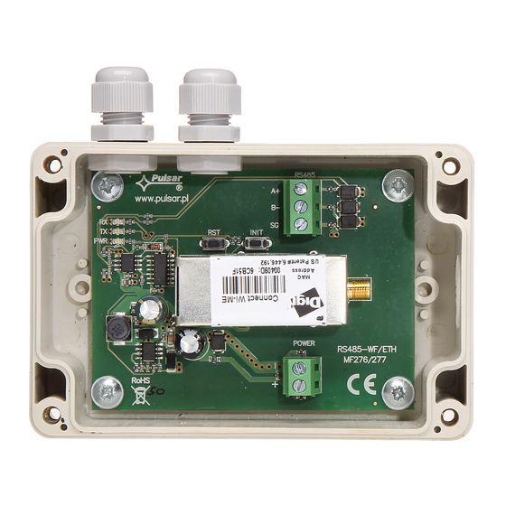
3.2 Connecting to the RS485 bus. The RS485-WiFi interface is connected to the RS485 bus via the ‘RS485’ connector. Connect the wires of the RS485 bus to the A+, B- terminals of the connector. They are assigned in the same way and the connection is identical to the rest of devices (A+ to A+, B- to B-). - Page 5 INTRW Fig.2. The view of the interface with a description of the wires.
-
Page 6: Configuration Of The Rs485-Wifi Interface
RS485-WiFi emits. To do so, unscrew the antenna of the interface and place it near the router with which it is going to be connected. -
Page 7: Step 2 - Configuration Of The Ip Address
Then, use the ‘Digi Device Discovery’ program as help. First, run the program (Digi Device Discovery). After launching, the program will display the logged-in RS485-WiFi interface. Identification of our module can be done by comparing the MAC addresses. Fig. 4. The window of the ‘Digi Device Discovery’ program showing a logged-in interface. -
Page 8: Step 3 - Assigning The Ssid Identifier For Wi-Fi Network
In this manual, the configuration of the Wi-Fi interfaces has been based on a wireless 'LinkSys WRT54GL’ Wi-Fi router. To make certain that the RS485-WiFi interface will be connected only to an appointed router, enter the network identifier. To do that, log into the interface’s router configuration as follows: open the window of a web browser, type 192.168.1.1 in the address field (router’s default address after a reset) and approve with the ‘ENTER’... - Page 9 INTRW Choose the ‘Wireless’ tab. Now, type the SSID network identifier which is the name of the network within which the Wi-Fi interfaces will be transmitting data to the computer. In the ‘Wireless Network Name’ field, type any name, e.g. ‘PowerSecurity’. Other settings shall remain unchanged.
- Page 10 INTRW Fig. 10. The panel of the interface’s configuration. On the left from the window, there is a menu. Choose the ‘Network’ option from the ‘Configuration’ group. Another window will be loaded. Choose ‘WiFi LAN settings’ at the bottom. The following window will appear: Fig.
- Page 11 INTRW From the same window, choose the ‘WiFi Security Settings’ tab at the bottom. Settings from this tab are responsible for protection against attempts of unauthorized connection by other users. In the tabs: ‘Network Authentication’ and ‘Data Encryption’ choose these methods of authentication and data encryption that are supported by the router in use.
- Page 12 INTRW Such implemented changes shall be approved by clicking the ‘Apply’ button. After that, the message informing about approved changes will appear. Now the interface has been reprogrammed. However, to make it operate accordingly to the adjustments, it needs to be reset, but only after adjusting the router.
-
Page 13: Step 4 - Selecting The Communication Mode
The topology of the network is based on wireless Wi-Fi router connected to another PSU segments (connected in the RS485 bus) via the RS485-WiFi interface. Each interface has a static IP address. Communication between a PC and the final PSU is by giving the IP address of the interface, the address of the PSU in the RS485 network and the number of the port responsible for the communication. - Page 14 To configure the function of redirecting the connection, give the IP address of the RS485-WiFi interface and the number of the port responsible for the communication.
-
Page 15: Tcp Sockets Profile Settings
INTRW TCP Sockets profile settings. After logging in the interface configuration page, select the ‘Serial Ports’ option from the ‘Configuration’ group. Then, select ‘TCP Sockets’ from the ‘Select Port Profile’ window and approve your choice by clicking ‘Apply’. Caution! If the interface was configured before, the ‘Serial Port Configuration’ window with current profile will appear instead of ‘Select Port Profile…’. -
Page 16: Setting The Serial Port
Fig. 18. Configuration of communication parameters of the serial port. – the ‘TCP Settings’ tab. Reset the RS485-WiFi interface by pressing the ‘RST’ button on the module or by cutting off the power for a few seconds. After the reset, the connection between the interface and the router should be re-established after... -
Page 17: Settings In The Powersecurity Program
CONNECTION Type Modbus RTU – TCP/IP TCP Address The address of the RS485-WiFi interface in WLAN. Caution. If the connection is via WAN, use the public IP address of the router. TCP Port 2101 The number of the TCP port. - Page 18 Fig. 20. The PSU preview window. To set the connection between the RS485-WiFi interface and any PSU connected to the RS485, check whether the communication parameters of the power supply unit’s serial port are correct. The transmission parameters of the power supplies are preset to 19200 bauds 8E1.
-
Page 19: Communication In The Wlan Serial Bridge Mode
The topology of the network is based on a wireless router which serves as a bridge between two segments of the RS485 bus. Each bus is connected to the RS485-WiFi interface, where one is the Client, and other the Server. Each interface has a static IP address. Communication between a PC and the final PSU is by entering the PSU address in the RS485 bus. -
Page 20: Setting The Parameters Of The Serial Port
Fig. 24. Configuration of communication parameters of the serial port – ‘TCP Settings’ tab. Reset the RS485-WiFi interface by pressing the ‘RST’ button on the module or by cutting off the power for a few seconds. After the reset, the connection between the interface and the router should be re-established within... -
Page 21: Settings In The Powersecurity Program
INTRW Settings in the PowerSecurity program. For further configuration, the PowerSecurity program is required. Download it from the following page: http://www.pulsar.pl/pl/pliki/PowerSecurity.exe The program is saved as an executable file therefore does not require installation in the system. Run the PowerSecurity program and choose: Power supplies >... - Page 22 INTRW Fig. 26. The PSU preview window. To set the connection between the RS485-WiFi interface and any PSU connected to the RS485, check whether the communication parameters of the power supply unit’s serial port are correct. The transmission parameters of the power supplies are preset to 19200 bauds 8E1. If the values were altered before, make the settings again accordingly to the information from the chapter: ‘Setting the communication parameters of the PSU’.
-
Page 23: Setting The Communication Parameters Of The Psu
INTRW 5. Setting the communication parameters of the PSU. Communication in the RS485 bus requires setting appropriate communication parameters in all power supply units and assigning appropriate addresses. Configuration in PSBEN power supply units is via the display mount in the faceplate of the enclosure. The configuration procedure is different for an LED and LCD display. -
Page 24: Setting The Parameters Of The Serial Port
INTRW Setting the parameters of the serial port. To enter the settings mode, press the ‘SET’ button from the main screen level. - with ‘>’ or ‘<’ set the menu - press the ‘SET’ button - with ‘>’ or ‘<’ set the... -
Page 25: Configuration Of The Psu With An Led Display
INTRW 5.2 Configuration of the PSU with an LED display. Setting the address of the PSU. - press the ‘<,>’ right and left-most buttons simultaneously on the LED panel - when the abbr ‘Adr’ appears, press ‘OK.’ - with ‘>’ or ‘<’ set the address from 1 to 247 - approve the set address with the ‘OK’... -
Page 26: Specifications
INTRW - now, one of the following abbreviations will be displayed: ‘8n2’, ‘8E1’ or ‘8o1’ - with ‘>’ or ‘<’ set the ‘8E1’ parameter - approve your choice with the ‘OK’ button - finish the configuration procedure by pressing simultaneously the ’<,>’ buttons 6. - Page 27 INTRW...
- Page 28 According to the EU WEE Directive – It is required not to dispose of electric or electronic waste as unsorted municipal waste and to collect such WEEE separately. WARRANTY Pulsar K.Bogusz Sp.j. 5 years from the date of production. Siedlec 150, 32-744 Łapczyca, Poland THE WARRANTY IS VALID only upon presentation Tel.
Need help?
Do you have a question about the RS485-WiFi and is the answer not in the manual?
Questions and answers