
Related Manuals for USTER HVI SPECTRUM


Summary of Contents for USTER HVI SPECTRUM
- Page 1 ® HVI SPECTRUM USTER Instruction Manual HIGH VOLUME FIBER TEST S YSTEM Date: June 2008 Part Number: 255-450-00671 English...
- Page 3 (90) days from the date of receipt. Due to the complex nature of the programs, Uster Technologies, Inc. does not warrant that the licensed programs are completely error-free, will operate without interruption, or are compatible with all equipment and software configurations.
- Page 4 Failure to supply specified electrical and air requirements will void the warranty. The warranty period is 12 months from the date the instrument is installed at the purchaser’s site, or 18 months from the date the instrument is shipped from the Uster Technologies, Inc. factory.
-
Page 5: Table Of Contents
URPOSE ..............1-1 NTRODUCTION ......... 1-2 ISUAL SED IN THIS ANUAL ..........1-3 AJOR YSTEM ISTINCTIONS HVI SPECTRUM E ..........1-4 QUIPMENT ............... 1-6 YSTEM RAWING HVI SPECTRUM ......... 1-7 YSTEM ODULES Micronaire Module ........... 1-7 Length/Strength Module ..........1-8 Color/Trash Module .......... - Page 6 ® HVI SPECTRUM USTER Instruction Manual CHAPTER 3 SOFTWARE OVERVIEW ....3-1 ..............3-1 ONTROL YSTEM ................. 3-3 OFTWARE HVI SPECTRUM Main Menu........3-3 2.1.1 Testing ............3-4 2.1.2 Setup ............3-4 2.1.3 QualiProfile ..........3-5 2.1.4 Reports ............3-5 2.1.5 Bale Manager..........
- Page 7 Measurement Selection Tab ........6-12 General Setup Tab ..........6-13 Temperature and RH Tab......... 6-14 Retest Tolerance Tab ..........6-15 USTER® SCI Regression Coefficients ......6-17 2.6.1 Changing the SCI Equation......6-18 CHAPTER 7 TESTING PROCEDURES ..... 7-1 ................. 7-1 VERVIEW ........
- Page 8 ® HVI SPECTRUM USTER Instruction Manual Designing a New Report ........... 8-8 Modifying/Deleting a Report ........8-11 Generating a Report ..........8-12 Graphs ..............8-13 Creating a New Graph ........... 8-13 Deleting a Graph ........... 8-15 Generating a Graph ..........8-16 Exporting Data ............
- Page 9 4.7.1 View Inventory Bale Data ......10-31 4.7.2 View Mix History........10-32 4.7.3 View Mix History Details ......10-33 4.7.4 View Mix History Histograms ...... 10-34 4.7.5 View Mix History Trends......10-35 CHAPTER 11 USTER® QUALIPROFILE ....11-1 ..............11-1 NTRODUCTION ..............11-3 UALI ROFILE Selecting a Profile...........
- Page 10 ® HVI SPECTRUM USTER Instruction Manual Disk Operating System ..........14-3 Monitor Information ..........14-4 Printer Information ..........14-4 Balance Configuration ..........14-5 Recommended Lot Limits for Cotton ......14-7 Transmission Architecture......... 14-8 Universal Record Format........14-10 HVI SPECTRUM Record Formats......14-12 2.9.1 Length/Strength ........
- Page 11 Figure 3-3: Main Menu.........3-3 Figure 3-4: Testing Button ............3-4 Figure 3-5: Setup Button ..............3-4 Figure 3-6: USTER® QualiProfile Button .........3-5 Figure 3-7: Reports Button ............3-5 Figure 3-8: Bale Manager Button ..........3-5 Figure 3-9: Help Button...............3-6 Figure 3-10: About Screen ............3-6 Figure 3-11: Quit Button .............3-6...
- Page 12 Figure 6-13: Measurement Selection Tab ........6-12 Figure 6-14: General Setup Tab ..........6-13 Figure 6-15: Screen Temperature and RH Tab ......6-14 Figure 6-17: Reset Tolerances Tab ..........6-16 Figure 6-18: USTER® SCI Regression Coefficients Tab....6-18 Chapter 7 Figure 7-1: Main Menu ..............7-3 Figure 7-2: Testing Button ............7-4 Figure 7-3: Testing Mode Selection Screen........7-4...
- Page 13 ® HVI SPECTRUM USTER Instruction Manual Figure 8-2: Reports Menu Screen ..........8-1 Figure 8-3: M ..............8-2 Figure 8-4: Reports Screen Menu Options ........8-3 Figure 8-5: Categories Screen .............8-3 Figure 8-6: Report Design Screen..........8-8 Figure 8-7: Report Design Screen – Lower Section......8-9 Figure 8-8: Run a report Screen ..........8-12...
- Page 14 ® HVI SPECTRUM USTER Instruction Manual Figure 10-23: Mix History Histogram Screen ......10-34 Figure 10-24: View Mix History Trends........10-35 Figure 10-25: View Mix History Trends – Date Range / Calendar 10-36 Chapter 11 Figure 11-1: Graph Example 1..........11-2 Figure 11-2: Graph Example 2..........11-2 Figure 11-3: Main Menu ............11-3...
-
Page 15: Chapter 1 Overview
Chapter 1 Overview Purpose This manual is intended for those operators who are responsible for the HVI SPECTRUM operation of the Uster Technologies’ instrument. It contains the information necessary to setup the system, perform calibrations, test fibers, and generate/analyze data using user-defined... -
Page 16: Visual Cues Used In This Manual
® HVI SPECTRUM USTER Instruction Manual Visual Cues Used in this Manual WHAT YOU SEE WHAT IT MEANS letters in bold are used for BOLD SMALL CAP MALL CAPITAL on-screen button names (i.e. select the T ESTING button to access the T screen). -
Page 17: Major System Distinctions
® HVI SPECTRUM USTER Instruction Manual • Bulleted or numbered statements indicate that the operator must perform an action in order to complete the procedure or instructions. • Information, such as a list of materials, features, components, etc. will appear in bulleted form. -
Page 18: Hvi Spectrum Equipment
® HVI SPECTRUM USTER Instruction Manual HVI SPECTRUM Equipment INSTRUMENT COMPONENTS/SOFTWARE HVI SPECTRUM Length, Strength, Micronaire, Maturity, and Moisture Components; Reports, Bale Manager, and QualiProfile Software HVI SPECTRUM Length, Strength, Micronaire, Maturity, Moisture, Color, and Trash Components; Reports, Bale Manager, and QualiProfile Software... - Page 19 ® HVI SPECTRUM USTER Instruction Manual Computer Hardware: • Computer system with CD-ROM drive, 3.5-inch floppy drive, 4.1 GB or better hard drive, and Pentium processor • IBM Flat Monitor • Keyboard with Touch Pad Feature • Balance • Printer...
-
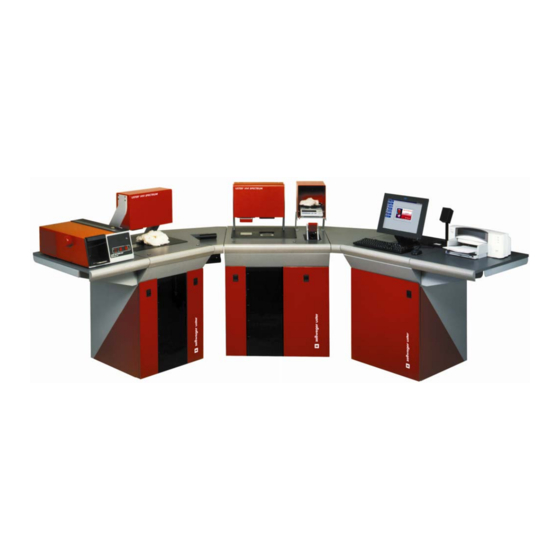
Page 20: System Drawing
® HVI SPECTRUM USTER Instruction Manual System Drawing HVI SPECTRUM Instrument displayed below shows all available options. Figure 1-1: Instrument with ALL optional modules Uster Technologies, Inc. Chapter 1 Overview • Page 1-6... -
Page 21: Hvi Spectrum System Modules
Instruction Manual HVI SPECTRUM System Modules HVI SPECTRUM system is housed in two floor-standing cabinets HVI SPECTRUM II (three units if you have purchased the with the additional Length/Strength and Color/Trash modules). • One cabinet contains the Length/Strength, Micronaire, and Color/Trash modules. -
Page 22: Length/Strength Module
® HVI SPECTRUM USTER Instruction Manual Length/Strength Module The Length/Strength module optically determines fiber lengths and their associated uniformity. The elongation is calculated by averaging the length of distance the fibers will extend before breaking. The strength is determined by measuring the force that is required to break a sample of a known mass. -
Page 23: Moisture Probe
® HVI SPECTRUM USTER Instruction Manual Moisture Probe The moisture probe is mounted on the pressure plate that measures the Color/Trash. If there is no Color/Trash module, the glass plate will be replaced with a filler plate. Software Features HVI SPECTRUM uses a windows-based operating system with icon- based software. -
Page 24: Keyboard Commands
® HVI SPECTRUM USTER Instruction Manual 8.1.1 Keyboard Commands Pressing the ENTER key on the keyboard registers an entry into the computer. An entry can be erased any time before pressing this key and corrected by using the BACKSPACE key. -
Page 25: Labels
® HVI SPECTRUM USTER Instruction Manual Safety Labels This label is located in front of the colorimeter unit. Caution should be taken to avoid crushing your hand as the top of the colorimeter chamber is activated. Figure 1-2: Crush Hazard Label... -
Page 26: Figure 1-6: Hvi Spectrum Equipment Label
® HVI SPECTRUM USTER Instruction Manual This warning label is located on HVI SPECTRUM the frame of the instrument behind each of the front and rear cabinet doors as well as on the control box. It indicates that hazardous voltage is under these covers. -
Page 27: Chapter 2 Installation
Immediately report any loss or damage to the carrier. IMPORTANT: For warranty purposes, ALL crates must be opened by a qualified Uster Technologies’ service technician. It is important that you DO NOT OPEN the crates or attempt to set up the system by yourself. -
Page 28: Electrical Requirements
These instructions MUST be performed for each cabinet at the time of installation with the assistance of an Uster Technologies’ service technician. Electrical Requirements HVI SPECTRUM instrument operates on 208 or 230 volts ± 10% (single phase) (47 to 63 Hz) and requires a separate dedicated 20-amp circuit breaker at the facility’s electrical load center. -
Page 29: Air Requirements
® HVI SPECTRUM USTER Instruction Manual Air Requirements The system pressure should be regulated between 100psi and 150psi clean, dry, unregulated compressed air. Use of dryer system, air filters and water trap is highly recommended. Air Pressure 100 - 120 PSIG (585-825 kPA) Amount of compressed air approx. -
Page 30: Uninterruptible Power Supplies (Ups)
Instruction Manual Uninterruptible Power Supplies (UPS) If you expect to have frequent power shutdowns, Uster Technologies recommends that an Uninterruptible Power Supply (UPS) device be used to prevent loss of data or other related problems. The input for the UPS, which powers the computer and monitor, is located on the back of the main cabinet beside the power entry connector. -
Page 31: Standard Hvi Spectrum
® HVI SPECTRUM USTER Instruction Manual HVI SPECTRUM Standard • The main control cabinet is 63 cm long and 80 cm deep. • The Length/Strength cabinet is 85 cm long by 89 cm deep. • The Length/Strength cabinet is connected to the main control system cabinet by a triangular-shaped support frame that is 69 cm at the widest part. -
Page 32: Hvi Spectrum I
® HVI SPECTRUM USTER Instruction Manual HVI SPECTRUM I • The main control cabinet is 64 cm long and 80 cm deep. • The Length/Strength cabinet is 84 cm long by 80 cm deep. • The Length/Strength cabinet is connected to the main control cabinet by a triangular-shaped support frame that is 70 cm at the widest part. -
Page 33: Hvi Spectrum
® HVI SPECTRUM USTER Instruction Manual HVI SPECTRUM II • The main control cabinet is 64 cm long and 80 cm deep. • The Length/Strength cabinet is 89 cm long by 80 cm deep. • The Length/Strength cabinet is connected to the main control cabinet by a triangular-shaped support frame that is 70 cm at the widest part. - Page 34 ® HVI SPECTRUM USTER Instruction Manual HVI SPECTRUM II Figure 2-3: Uster Technologies, Inc. Chapter 2 Installation • Page 2-8...
-
Page 35: Connections
“KB” on the back of the computer. It is equipped with a touch pad feature for easy use. Older versions of the HVI SPECTRUM units are equipped with a Note: keyboard and mouse, which are installed in the same manner. - Page 36 ® HVI SPECTRUM USTER Instruction Manual Uster Technologies, Inc. Chapter 2 Installation • Page 2-10...
-
Page 37: Chapter 3 Software Overview
Chapter 3 Software Overview Control System IMPORTANT: Please note that the screens shown in this manual depict HVI SPECTRUM I instrument. If you are using an SPECTRUM II instrument, the screens that you see on your monitor may differ slightly. -
Page 38: Figure 3-2: Power Button/Vacuum Blower Button
® HVI SPECTRUM USTER Instruction Manual The VACUUM BLOWER and the POWER button are located on the (see below) top of control cabinet . The Power button is RED, whereas the Vacuum Blower button is YELLOW. Vacuum Blower Power (YELLOW... -
Page 39: Software
® HVI SPECTRUM USTER Instruction Manual Software HVI SPECTRUM The software for the system is installed on the hard disk drive (C:\HVI). When the system is turned on, the software performs a HVI SPECTRUM series of checks and the is displayed. -
Page 40: Testing
Instruction Manual Note: The example above applies to all function buttons with the exception of the T button. When the testing screens are exited, ESTING all functions on the HVI SPECTRUM M are enabled. 2.1.1 Testing The T button is used to perform the normal ESTING testing process of fibers. -
Page 41: Qualiprofile
USTER Instruction Manual 2.1.3 QualiProfile The USTER® QualiProfile enables the operator to see at first glance if a yarn is appropriate for a specific application and to compare it with USTER® Statistics. Additional information can be found in Chapter 11 . -
Page 42: Help
OFF at the end of each testing day; however, the instrument should be left ON. Note: Various HVI SPECTRUM screens contain “On/Off” fields that are used to activate or deactivate a function of the system. If the field is checked (using the keypad or spacebar), the feature is in the ON position. -
Page 43: Resetting The System
® HVI SPECTRUM USTER Instruction Manual Resetting the System HVI SPECTRUM The main purpose of resetting the system is to clear the software of unnecessary information. Resetting erases old values from the system's memory buffer. If the system is reset in the middle of a testing sequence, the result will be a loss of test data. - Page 44 ® HVI SPECTRUM USTER Instruction Manual Uster Technologies, Inc. Chapter 3 Software Overview • Page 3-8...
-
Page 45: Chapter 4 Calibration
This chapter explains how this is accomplished. Calibration cottons and the standard color tiles supplied by Uster Technologies, Inc. MUST BE USED to calibrate and to check calibrations. If you need to obtain calibration cotton samples, they... -
Page 46: Cotton Calibration
® HVI SPECTRUM USTER Instruction Manual Cotton Calibration To better understand the theory behind calibration procedures, it is important to know the instrument/software principles of calibration. Calibration is performed following engineering principles using hardware devices. Adjustments are then made within the instrument to the unadjusted, raw values through software manipulations. - Page 47 ® HVI SPECTRUM USTER Instruction Manual If a "Fail" condition occurs during a calibration, changes are made to the parameters. However, ONLY those parameters that are critical for calibration to be brought to a "Pass" condition will change. In other words, no changes are made to those parameters that pass calibration originally.
-
Page 48: Module Calibration
Instruction Manual Module Calibration The frequency of routine calibrations has been drastically reduced due HVI SPECTRUM to the innovative design of Uster Technologies’ . It is suggested, however, that a routine calibration check on each module be completed once a day. -
Page 49: Figure 4-2: Calibration Screen
® HVI SPECTRUM USTER Instruction Manual • The C screen shown below is displayed: ALIBRATION Figure 4-2: Calibration Screen Note: Although, testing for both units must be completed, HVI SPECTRUM II operators can choose which Colorhead to use first by selecting either Unit 1 or Unit 2. -
Page 50: Length/Strength Calibration
WARNING! HVI SPECTRUM system operators SHOULD NOT USE . It is intended for use by Certified ACTORY ALIBRATION Uster Technologies’ service technicians only and cannot be accessed without the proper password. Uster Technologies, Inc. Chapter 4 Calibration • Page 4-6... -
Page 51: Length/Strength And Uniformity Calibration
® HVI SPECTRUM USTER Instruction Manual 3.1.1 Length/Strength and Uniformity Calibration button is used to access the ENGTH TRENGTH AND NIFORMITY screen, which is necessary to calibrate LENGTH TRENGTH ALIBRATION specific components. 1. Select the L button from the ENGTH... - Page 52 HVI SPECTRUM USTER Instruction Manual Note: HVI Spectrum II operators must select either Length/Strength Unit 1 or Unit 2 from the pull-down list, which is located to the left of button. This choice will designate which unit will complete TART testing first.
- Page 53 ENGTH TRENGTH ALIBRATION MENU button on the LENGTH TRENGTH ALIBRATION IALOG Note: Factory Calibration screens are intended for certified Uster Technologies’ Service Technicians and cannot be accessed without the proper password. Uster Technologies, Inc. Chapter 4 Calibration • Page 4-9...
-
Page 54: Micronaire Calibration
This gives you access to the ICRONAIRE ALIBRATION Figure 4-5: Micronaire Calibration Menu IMPORTANT: DO NOT use the M button. ONLY a ICRONAIRE ETUP qualified Uster Technologies’ service technician should access this screen. Uster Technologies, Inc. Chapter 4 Calibration • Page 4-10... - Page 55 ® HVI SPECTRUM USTER Instruction Manual Select the M button to access the ICRONAIRE ALIBRATION shown below: ICRONAIRE ALIBRATION SCREEN Figure 4-6: Micronaire Calibration Screen Enter the low and high micronaire standard values in the appropriate fields. Once this is done, select the S button.
-
Page 56: Calibration Procedures For Micronaire
® HVI SPECTRUM USTER Instruction Manual Continue the process by following the on-screen messages to test the high-Micronaire sample. 10. Once all tasks have been completed as directed by the on-screen prompts, select the S button. You can interrupt the... -
Page 57: Color Calibration
Note: If an error message appears repeatedly, it could indicate an air leak in the Micronaire chamber. If this occurs, perform a Micronaire calibration check to ensure that it is accurate. If necessary, contact an Uster Technologies’ service technician for further support. Color Calibration HVI SPECTRUM... -
Page 58: Figure 4-8: Color Reference Values Screen
Figure 4-8: Color Reference Values Screen In this screen, the Rd and +b values are displayed for each tile. Check these values with each tile supplied by Uster Technologies, Inc. to ensure that the displayed figures are the same as those printed on the calibration tile box. - Page 59 ® HVI SPECTRUM USTER Instruction Manual IMPORTANT: The FIRST time the system is calibrated, D EFINED TILE MUST be selected! Refer to COLOR IXED TILE SEQUENCE figure 4 – 9. Begin calibration by selecting the S button. TART 10. The “Message” area, located beneath the list of tiles, offers instructions to the operator.
-
Page 60: Figure 4-10: Color Calibration Screen - Results
® HVI SPECTRUM USTER Instruction Manual Note: After the defined sequence has been measured for the first time, the system can generally determine which tile is on the window with the exception of the central tile. Figure 4-10: Color Calibration Screen – Results 17. -
Page 61: Trash Calibration
® HVI SPECTRUM USTER Instruction Manual Trash Calibration HVI SPECTRUM The trash module used in the instrument has been designed to operate for an extended period of time without requiring routine check calibration. It is recommended that a be performed... -
Page 62: Procedures For Flash Calibration
® HVI SPECTRUM USTER Instruction Manual Note: If you have the HVI SPECTRUM II, select which Length/Strength Unit will be used for testing by clicking in the circle beside either “Unit 1” or “Unit 2”. The C screen will appear:... -
Page 63: Procedures For Trash Calibration
® HVI SPECTRUM USTER Instruction Manual IMPORTANT: The Tile and sample glass must be void of any trash or other contaminants that could be seen by the camera. Both can be cleaned with a soft dry cloth or, if necessary, use a small amount of soapy water. See IMPORTANT instructions for cleaning trash tile on the next page. - Page 64 Be sure to click the S ALIBRATION button to save the results when you are finished. Note: Once calibration is complete, you can select Print Results. ontact an Uster Technologies’ service technician for Note: assistance if repeated failures occur. Uster Technologies, Inc.
-
Page 65: Temperature And Humidity Calibration
® HVI SPECTRUM USTER Instruction Manual Temperature and Humidity Calibration The optional temperature and humidity probe is calibrated as follows: HVI SPECTRUM First, select the S button from the ETUP , select the C button. ALIBRATE Figure 4-13: Main Menu - Setup Uster Technologies, Inc. -
Page 66: Figure 4-14: Temperature And Humidity Calibration
® HVI SPECTRUM USTER Instruction Manual Select the T button from the C EMP AND UMIDITY ALIBRATION screen (refer to Figure 4-2) to access the T EMPERATURE AND screen. UMIDITY ALIBRATION Figure 4-14: Temperature and Humidity Calibration When this screen opens, readings are automatically taken and displayed on the screen for the operator to view. -
Page 67: Uv Meter Calibration
® HVI SPECTRUM USTER Instruction Manual UV Meter Calibration The UV C screen shows real-time updates of the HECK ALIBRATION values coming from the UV meter. This calibration supports the original “single tile” mode, or “multiple tiles” for a more accurate calibration over a wider range of UV values. - Page 68 ® HVI SPECTRUM USTER Instruction Manual Note: Calibration at X1 is REQUIRED. To perform the check: Place the dark side of the tile on the plate and take a reading. The UV reading should equal 0 (zero). If the values are correct, no calibration is necessary. Select the button.
-
Page 69: Chapter 5 System Check
® HVI SPECTRUM USTER Instruction Manual Chapter 5 System Check Overview The S button replaces the CAL YSTEM HECK button found on previously used HECK software versions. This feature is designed to assist in checking calibration. Figure 5-1: System Check Button... -
Page 70: Micronaire
® HVI SPECTRUM USTER Instruction Manual Micronaire 2.1.1 Calibration Check To check micronaire calibration: HVI SPECTRUM Select the S button from the ETUP Press the S button. YSTEM HECK Figure 5-2: Main Menu - S ETUP Uster Technologies, Inc. Chapter 5... -
Page 71: Figure 5-3: System Check Test Selection Menu
® HVI SPECTRUM USTER Instruction Manual This gives you access to the S YSTEM HECK ELECTION Figure 5-3: System Check Test Selection Menu Uster Technologies, Inc. Chapter 5 System Check • Page 5-3... -
Page 72: Figure 5-4: System Check Micronaire Screen
® HVI SPECTRUM USTER Instruction Manual Click the M button on the S ICRONAIRE YSTEM HECK ELECTION This gives you access to the S screen: YSTEM HECK ICRONAIRE Figure 5-4: System Check Micronaire Screen Uster Technologies, Inc. Chapter 5 System Check • Page 5-4... -
Page 73: Calibration Test
® HVI SPECTRUM USTER Instruction Manual 2.1.2 Calibration Test To begin a calibration test: Enter the Lot ID and Bale ID information in the corresponding fields. Begin the testing procedure by weighing and measuring the efer to Chapter 4 of this manual for complete sample. -
Page 74: Length/Strength
® HVI SPECTRUM USTER Instruction Manual Length/Strength 2.2.1 Calibration Check To check Length/Strength Calibration: HVI SPECTRUM Select the S button from the ETUP screen. Press the S button. YSTEM HECK Click on the L button located on the S ENGTH... -
Page 75: Calibration Test
Save any changes by pressing the S STD V button. ALUES Note: HVI SPECTRUM II users must select either L/S Unit 1 or L/S Unit 2 from the pull-down list. Press the S button. TART When testing is finished, select the E button. -
Page 76: Color/Trash
® HVI SPECTRUM USTER Instruction Manual Color/Trash 2.3.1 Calibration Check To check Color/Trash calibration: HVI SPECTRUM Select the S button from the ETUP Press the S button. YSTEM HECK Click on the C button located on the S OLOR RASH... -
Page 77: Chapter 6 Configurations
® HVI SPECTRUM USTER Instruction Manual Chapter 6 Configurations Introduction HVI SPECTRUM is a versatile instrument, which can be configured to meet the testing needs of a variety of mills and gins. The screen is used to adjust various system settings as ONFIGURATION needed. -
Page 78: Test Setup Tab
® HVI SPECTRUM USTER Instruction Manual Test Setup Tab As the S screen opens, the T tab is YSTEM ONFIGURATION ETUP displayed. It has been chosen as the default tab because it is used more frequently than the remaining tabs. - Page 79 ® HVI SPECTRUM USTER Instruction Manual The T tab contains information that is ETUP crucial to test results. The fields are explained as follows: The Database and External Computer Transmit options are used to indicate where the data generated during the testing is to be sent.
- Page 80 ® HVI SPECTRUM USTER Instruction Manual Trashmeter turns the trash meter off/on during testing. A Trashmeter Measurement is generally used whenever color/trash is measured. This function SHOULD NOT BE TURNED OFF unless the camera is not working properly. The Moisture Correction field is used to turn ON the moisture correction calculations during the strength tests.
-
Page 81: Lot Limits
Note: The HVI SPECTRUM software allows up to twenty-two (22) sets of lot limits to be saved. To use a previously defined Lot Limit: Select the lot limit name by using the arrow keys to highlight your selection from the Lot Limits drop down box. -
Page 82: Creating Lot Limits
® HVI SPECTRUM USTER Instruction Manual 2.1.2 Creating Lot Limits Follow these steps to create new lot limits: HVI SPECTRUM Select S from the ETUP Click on the L button. IMITS Figure 6-3: Main Menu - Setup Uster Technologies, Inc. -
Page 83: Figure 6-4: Lot Limits Screen
® HVI SPECTRUM USTER Instruction Manual The following L screen will appear: IMITS Figure 6-4: Lot Limits Screen Select the N button, which is located to the right of the Name field. Enter a name for the new lot limit and move the cursor to the first property you want to have a lot limit. -
Page 84: Figure 6-5: Error Message - Lot Limit Name Already Exists
® HVI SPECTRUM USTER Instruction Manual IMPORTANT: You cannot use an existing name when adding a new lot limit; THE NAME MUST BE UNIQUE. If you accidentally select an existing lot limit, an error message will appear. Figure 6-5: Error Message - Lot Limit Name Already Exists... -
Page 85: Edit Lot Limits
® HVI SPECTRUM USTER Instruction Manual 10. A N appears, select OK. dialog box IMIT ADDED Figure 6-7: New Lot Limit Added 2.1.3 Edit Lot Limits Follow these steps to edit lot limits: Select the Lot Limit to be edited from the “Name” field drop down box on the L screen. -
Page 86: Figure 6-9: Lot Limit Updated
® HVI SPECTRUM USTER Instruction Manual Edit or change the lot limit data. Select the OK button located at the bottom of the screen when you are finished. At the L prompt select OK. OT LIMIT UPDATED Figure 6-9: Lot limit updated Uster Technologies, Inc. -
Page 87: Delete Lot Limits
® HVI SPECTRUM USTER Instruction Manual 2.1.4 Delete Lot Limits To delete a lot limit: Select the lot limit to be deleted from the Name field drop down box on the L screen. IMITS Select the D button. ELETE Figure 6-10: Lot Limits Screen - Delete A warning dialog box, “D... -
Page 88: Measurement Selection Tab
® HVI SPECTRUM USTER Instruction Manual Measurement Selection Tab HVI SPECTRUM Select the S button from the ETUP Next, select the C button. ONFIGURE The S screen will appear: YSTEM ONFIGURATION Figure 6-12: Measurement Selection Tab The M tab is used to select the... -
Page 89: General Setup Tab
® HVI SPECTRUM USTER Instruction Manual Select the A button when you have finished. PPLY If you want to continue making changes to other configuration settings, choose another tab from the S YSTEM ONFIGURATION screen. Press the OK button when you are finished. -
Page 90: Temperature And Rh Tab
Uster Technologies’ service technician during initial installation. Note: Cabinet 1 and 2 are also referred to as Color head Unit 1 and 2 and are used on the HVI SPECTRUM II. Temperature and RH Tab Access the S... -
Page 91: Retest Tolerance Tab
® HVI SPECTRUM USTER Instruction Manual The T RH tab is used to set the upper and lower EMPERATURE AND limits for temperature and relative humidity. Selections to turn these features on/off are offered in addition to an alarm on/off selection. - Page 92 ® HVI SPECTRUM USTER Instruction Manual Figure 6-15: Reset Tolerances Tab The R tab allows the range between the ETEST OLERANCES maximum and minimum values of a sample to be measured. If the difference between the test values is greater than the retest tolerance, the operator is notified by a warning message.
-
Page 93: Uster® Sci Regression Coefficients
HVI SPECTRUM USTER Instruction Manual USTER® SCI Regression Coefficients The USTER® Spinning Consistency Index (SCI) is a calculated value based on multiple regression analyses that compare fiber properties to HVI SPECTRUM yarn properties. Each equation takes into account the properties and calculates one value to be used on each test sample. -
Page 94: Changing The Sci Equation
Add the results to the -412.7 constant (i.e. -412.7 +48.1= -364.6). Change the constant coefficient from -412.7 to -364.6. Replace the Rd coefficient with zero. Figure 6-16: USTER® SCI Regression Coefficients Tab Enter the Actual SCI Regression Coefficients amounts in each field. -
Page 95: Chapter 7 Testing Procedures
HVI SPECTRUM can be purchased with a combination of components and software. Depending on this combination, you may HVI SPECTRUM, HVI SPECTRUM I HVI SPECTRUM II have the , or Below is a breakdown of which instrument contains what components. -
Page 96: Testing Sequence Quick Reference
HVI SPECTRUM USTER Instruction Manual Note: The information provided in this instruction manual was written using the HVI SPECTRUM I Instrument. However, it encompasses the procedures that are used to operate all configurations. Testing Sequence Quick Reference The fiber testing sequence can be summarized as follows: 1. -
Page 97: Step 1-Access The Main Testing Screen
® HVI SPECTRUM USTER Instruction Manual b) Simultaneously, press down on each of the two buttons, which are located on the tabletop of the measuring components. c) The sample hands will compress the samples to eliminate air pockets and the measurements will be taken. The sample hands will return to the original resting position when finished. -
Page 98: Step 2-Choose From Additional Selections
® HVI SPECTRUM USTER Instruction Manual The T button accesses all areas of the ESTING testing software. Figure 7-2: Testing Button HVI SPECTRUM • Begin testing by selecting the T button on the ESTING Step 2—Choose from Additional Selections • Once Step 1 has been completed, the T... -
Page 99: Step 3-Operator Identification
HVI SPECTRUM USTER Instruction Manual Step 3—Operator Identification Note: When the HVI SPECTRUM software is initialized at the beginning of each shift or after a system shutdown, the identification number of the current testing operator must be entered. • The O ID E opens. -
Page 100: Step 4-Identify The Sample
Note: Shaded items indicate either optional modules or items that have been set to the OFF position on the Test Setup screen. This screen is accessed by first selecting the button on the HVI SPECTRUM ETUP and then the C button. -
Page 101: Step 5-Perform The Micronaire Test
Note: Once Lot ID is entered; it is carried over when the next bale from the same lot is tested. When testing bales from a new lot, you must re-enter from the HVI SPECTRUM T screen to change the ESTING Lot ID. - Page 102 Note: If an error message appears repeatedly, it could indicate an air leakage in the micronaire chamber. In such a case, perform a micronaire calibration check to ensure that it is accurate. If necessary, contact an Uster Technologies’ Service technician for further support. Uster Technologies, Inc. Chapter 7...
-
Page 103: Step 6-Perform L/S And C/T (Optional Module) Tests
® HVI SPECTRUM USTER Instruction Manual Step 6—Perform L/S and C/T (Optional Module) Tests Once the micronaire tests are completed, follow the steps below to perform the length/strength and color/trash tests. Remember to activate the Vacuum Blower or the test results will FAIL! •... -
Page 104: Exit From Testing
® HVI SPECTRUM USTER Instruction Manual Exit from Testing When you have finished testing the samples for the specified lot, exit the screen by following these steps: • Select the E button. Attention: Be sure that you DO NOT exit System Testing until the test series for the last sample is completely finished. -
Page 105: Determining The Action When Cotton Fails To Meet Lot Limits
® HVI SPECTRUM USTER Instruction Manual Determining the Action when Cotton Fails to Meet Lot Limits This section explains the options you have when a cotton sample fails to meet one or more of the Lot Limits selected. When the M... -
Page 106: Figure 7-7: Bales Out Of Tolerance Dialog Box
® HVI SPECTRUM USTER Instruction Manual When all testing of a specific Lot Identifier is completed and you exit the S screen, the B YSTEM ESTING ALES OLERANCE IALOG will appear: Figure 7-7: Bales Out of Tolerance Dialog Box This dialog box shows you how many bales were out of tolerance. -
Page 107: Chapter 8 Reports
® HVI SPECTRUM USTER Instruction Manual Chapter 8 Reports Introduction HVI SPECTRUM As the USTER® collects fiber test results, the information is summarized and stored in the database. It is from this database that Reports are generated. HVI SPECTRUM is designed so that these reports can be arranged and sorted to present specific information for review and interpretation. -
Page 108: Categories
® HVI SPECTRUM USTER Instruction Manual Categories One method of analyzing data and warehousing cotton is by Category. Note: In depth instructions for categorizing fibers can be found in Chapter 14 . Creating Categories HVI SPECTRUM Select the R button from the... -
Page 109: Figure 8-4: Reports Screen Menu Options
® HVI SPECTRUM USTER Instruction Manual When the R screen is displayed, select C EPORTS ATEGORIES from the menu options. Figure 8-4: Reports Screen Menu Options The C screen is accessed at this time. ATEGORIES Figure 8-5: Categories Screen Uster Technologies, Inc. -
Page 110: Overview Of The Category System
This will also allow for small shifts the average inventory might make over a period of time. Uster Technologies, Inc. pre-defines the categories at the time of initial installation using suggested settings. If this pre-set definition does not correctly represent your inventory, it is important that you make the necessary adjustments. -
Page 111: Changing The Pre-Defined Categories
® HVI SPECTRUM USTER Instruction Manual Changing the Pre-Defined Categories When the categories are defined, the highest value of the first category is the starting point at which the intervals between the categories are added. The operator must determine what that interval will be and how many categories are necessary to cover the range of measured fiber properties. -
Page 112: Designing/Deleting/Modifying Reports
® HVI SPECTRUM USTER Instruction Manual Designing/Deleting/Modifying Reports Type and Format of Test Data When deciding how your reports will be designed (i.e. what information will be presented on each), consider the character spaces the data may require. Example: Reports generated by category require fewer character spaces;... - Page 113 ® HVI SPECTRUM USTER Instruction Manual Abbreviation Grade Trash Count Tr Cnt Trash Area Tr Area Trash Grade Tr Grade L Grade Leaf Grade Nep Count UV Value Temperature Temp Relative Humidity Table 8–2: Fiber Property Abbreviations - Table 2 Uster Technologies, Inc.
-
Page 114: Designing A New Report
® HVI SPECTRUM USTER Instruction Manual Designing a New Report HVI SPECTRUM is designed to be flexible with the type and format of the test data that is presented. The R selection located on the selection located on the EPORTS... -
Page 115: Figure 8-7: Report Design Screen - Lower Section
® HVI SPECTRUM USTER Instruction Manual The information that appears on the report is determined by the report properties chosen. A list containing all the available fiber properties is displayed in a window. o To select the report properties, simply highlight the property in... - Page 116 ® HVI SPECTRUM USTER Instruction Manual When the report is generated, it can include: Accepted Data — Only tests that are acceptable according to the lot limit specification at test time will be included in the report. Rejected Data — Only tests that are rejected according to the lot limit specification at test time will be included in the report.
-
Page 117: Modifying/Deleting A Report
® HVI SPECTRUM USTER Instruction Manual Modifying/Deleting a Report Once a report has been created, it can be modified or deleted as needed. • Select the name of the report from the drop down list on the R EPORT (Refer to Figure 8-6) screen. -
Page 118: Generating A Report
® HVI SPECTRUM USTER Instruction Manual Generating a Report HVI SPECTRUM Select R from the EPORTS The R launches. EPORTS To run a report, select the item from the menu EPORTS options. Select the R item from the drop-down menu. -
Page 119: Graphs
® HVI SPECTRUM USTER Instruction Manual Graphs HVI SPECTRUM As stated previously, the is designed to be flexible with the type and format of the test data that are presented. Therefore, in HVI SPECTRUM addition to providing a means of creating reports, the also provides a means to create graphs. -
Page 120: Figure 8-10: Graph Design Screen
® HVI SPECTRUM USTER Instruction Manual Figure 8-10: Graph Design Screen Note: The graph name will also be the title of the graph. If you are creating a Histogram, select the appropriate property from the pull-down list in the Graph Properties field. (This field is shaded out when creating a color chart because it doesn’t... -
Page 121: Deleting A Graph
® HVI SPECTRUM USTER Instruction Manual Deleting a Graph Once a graph has been created, it can be deleted as needed. Select the name of the graph from the drop down list on the G RAPH screen. ESIGN Select the D button. -
Page 122: Generating A Graph
® HVI SPECTRUM USTER Instruction Manual Generating a Graph HVI SPECTRUM First, select the R button from the EPORTS The R screen will appear. Select G from the EPORTS RAPHS menu options. To generate a graph, select the R item. The R... -
Page 123: Exporting Data
® HVI SPECTRUM USTER Instruction Manual Exporting Data HVI SPECTRUM Data generated by the unit can be exported in several formats to a variety of destinations. • To access the E screen, select the E menu XPORT XPORT DATA option from the R screen options. -
Page 124: Export Options
® HVI SPECTRUM USTER Instruction Manual 3.9.2 Export Options Export Options include: • User Named Disk File — Enter the path (if required) and file name in the field located to the right of this option (i.e. data to be stored in a file named EXPORT.DAT and written to a floppy disk in... -
Page 125: Using The
® HVI SPECTRUM USTER Instruction Manual HVI SPECTRUM 3.10 Using the Database As information is collected during testing, it is stored in the database. This information can be deleted by lot number or by record number by using the screens accessed by the D... - Page 126 ® HVI SPECTRUM USTER Instruction Manual Next, select the OK button to delete the records from the database. A confirmation dialog box will appear: Figure 8-14: Deleting Dialog Box Select the OK button. Uster Technologies, Inc. Chapter 8 Reports • Page 8-20...
-
Page 127: Delete Multiple Records For A Lot
® HVI SPECTRUM USTER Instruction Manual 3.11 Delete Multiple Records for a Lot This selection provides a mode for deleting records for multiple bales at one time. Select R from the M EPORTS Select D from the menu options on the R... - Page 128 ® HVI SPECTRUM USTER Instruction Manual Uster Technologies, Inc. Chapter 8 Reports • Page 8-22...
-
Page 129: Chapter 9 Quick Reports
® HVI SPECTRUM USTER Instruction Manual Chapter 9 Quick Reports Quick Reports Introduction Introduction Test results can be viewed and/or printed at any time during testing Test results can be viewed and/or printed at any time during testing HVI SPECTRUM... -
Page 130: Figure 9-2: Select Quick Report Screen - Summary
® HVI SPECTRUM USTER Instruction Manual Enter the Bale ID or highlight it from the pull down list in the Bale ID field. Press OK when you are finished. Note: When accessed from Micronaire Module Testing, I NDIVIDUAL is automatically selected when the S... -
Page 131: Figure 9-3: Quick Report Example
® HVI SPECTRUM USTER Instruction Manual Figure 9-3: Quick Report Example To print the report showing the results of all tests performed under the current Lot Identification number (since the last report was generated); select the P icon. RINTER Uster Technologies, Inc. - Page 132 ® HVI SPECTRUM USTER Instruction Manual Uster Technologies, Inc. Chapter 9 Quick Reports • Page 9-4...
-
Page 133: Chapter 10 Bale Manager
® HVI SPECTRUM USTER Instruction Manual Chapter 10 Bale Manager Overview Bale Manager is used to guide decisions on fiber procurement, facilitate warehousing, control short and long term variation within and between mixes, predict spinning performance, and prepare reports for review. -
Page 134: Accessing Bale Manager
® HVI SPECTRUM USTER Instruction Manual Accessing Bale Manager HVI SPECTRUM Select B from the ANAGER Figure 10-1: Main Menu Uster Technologies, Inc. Chapter 10 Bale Manager • Page 10-2... -
Page 135: Figure 10-2: Bale Manager Main Menu
® HVI SPECTRUM USTER Instruction Manual The B (shown below) will appear: ANAGER Figure 10-2: Bale Manager Main Menu Six main menu options, F , and ONFIGURE , access the various functions of the Bale Manager software. Uster Technologies, Inc. -
Page 136: Main Functions
® HVI SPECTRUM USTER Instruction Manual Main Functions The primary function of each of these menu items is described in the table shown below: Button Functions Name Used to import data from the default path or a:\ drive, as well as exit the Bale Manager software. -
Page 137: Data Import
® HVI SPECTRUM USTER Instruction Manual 3.1.1 Data Import The D screen is used to import data from an outside source. MPORT To access this screen follow the steps below: Select F from the B ANAGER Next, select the I item. - Page 138 ® HVI SPECTRUM USTER Instruction Manual When using the M Test Mode, a screen will appear showing ODULE the mean, standard deviation, and the percent coefficient of variance (%CV) of various properties (length, strength, Rd, +b, elongation, uniformity, etc.). If these values are correct, you can choose to accept the data and these averaged values will be applied to the lot.
-
Page 139: Exit
® HVI SPECTRUM USTER Instruction Manual In the event that the data has already been imported into the database, the following dialog box will appear: Figure 10-4: Bale Manager – Duplicate Data Detected 10. To abort the import attempt, select C ANCEL 11. -
Page 140: Configure
® HVI SPECTRUM USTER Instruction Manual Configure The C item found in the menu options on the B ONFIGURE ANAGER is used to access the following screens: • System Status • Categories • Growth Areas • Mix Criteria • SCI Calculation Each of these screens is explained in this chapter. -
Page 141: System Status
® HVI SPECTRUM USTER Instruction Manual 3.2.1 System Status The S screen is used to configure the system settings. YSTEM TATUS • Access the S screen by selecting the C menu YSTEM TATUS ONFIGURE item from the B . Select S... - Page 142 ® HVI SPECTRUM USTER Instruction Manual Note: All length measurements are stored in the database in inches and are converted as needed when the data is presented. • In the Date field, choose the format in which you want the date presented.
-
Page 143: Defining Categories
If Hopper is selected, then the number of hoppers in a row must be entered in the adjacent field. Note: The Automatic Import from HVI SPECTRUM can be turned off/on as needed. If no data is being imported via the import utility, this feature should be disabled. -
Page 144: Number Of Categories
® HVI SPECTRUM USTER Instruction Manual Number of Categories It is important to keep in mind that the number of categories for each property should be kept to the minimum required to adequately cover your inventory and to allow for the small shifts the average inventory might make over a period of time. -
Page 145: Defining Categories-Initial Definition
® HVI SPECTRUM USTER Instruction Manual Defining Categories—Initial Definition When initially defining the categories for inventory analysis, first estimate the average value and range of each measured property for the bales in inventory. • Use the values below to initiate histograms for each fiber property according to the procedures outlined in this section. -
Page 146: Define Categories To Reflect Inventory
® HVI SPECTRUM USTER Instruction Manual • Once you have determined what the values are that should be entered for the Category Definitions to reflect your inventory, you are ready to define the Categories. This section assumes that you have analyzed your inventory and know the numbers to be assigned for the Category Definition of each property. - Page 147 ® HVI SPECTRUM USTER Instruction Manual The Select Property field is used to indicate the property that is of the category being defined (i.e. Length/Strength, elongation, etc….). The cursor is positioned in the Highest Value of First Category field for the highest value for the first category. This is the value at which the fiber property's first category should end.
-
Page 148: Define Growth Areas
® HVI SPECTRUM USTER Instruction Manual 4.4.2 Define Growth Areas This selection allows the operator to add and/or delete specified growth e operator to add and/or delete specified growth areas. areas. Select the C Select the C menu item from the B... -
Page 149: Figure 10-9: Define Growth Areas - Edit Screen
® HVI SPECTRUM USTER Instruction Manual To rename a growth area, press the R button on the right. ENAME An E screen appears: Figure 10-9: Define Growth Areas - Edit Screen Enter the new name in the area provided on the E screen and click OK. -
Page 150: Define Proportional/Centered Mix Criteria
® HVI SPECTRUM USTER Instruction Manual 4.4.3 Define Proportional/Centered Mix Criteria Note: The title and function of this screen toggles between “Defining Proportional Mix Criteria” or “Defining Centered Mix Criteria.” (Refer to page 8 in part 3.2.1 for differences in these types of mixes) Selecting the appropriate mix mode on the System Status screen controls the setting. - Page 151 ® HVI SPECTRUM USTER Instruction Manual To Edit a Mix: Click in the radio button to the left of E in the Action DIT A area of the screen. Select the name of the mix from the pull-down list in the Mix Name field.
-
Page 152: Define Sci Calculations
® HVI SPECTRUM USTER Instruction Manual 4.4.4 Define SCI Calculations Select C from the B ONFIGURE ANAGER Next, select the SCI C item. The D SCI E ALCULATION EFINE QUATION screen will appear: Figure 10-11: Define SCI Equation Screen • SCI is a calculated value that is based on a regression analysis equation that compares fiber properties to yarn properties. -
Page 153: Changing The Sci Equation
® HVI SPECTRUM USTER Instruction Manual For example: Property Range Length 5/16 - 1 3/8 inches (23.8 - 34.9 mm) Strength 18 - 36 grams/tex Micronaire 2.8 - 5.8 4.4.5 Changing the SCI Equation The following equation should be used for installations when the SPECTRUM instrument has taken no color or trash measurements. -
Page 154: Edit
® HVI SPECTRUM USTER Instruction Manual Edit The E menu is used to access the following screens: • Bale Data - add new data and edit existing data. • Delete for Lot ID - delete bales for selected identifier. •... - Page 155 ® HVI SPECTRUM USTER Instruction Manual To Edit Existing Data: Press the E button. Enter the Lot ID and Bale ID or select them from the pull down lists. Position the cursor in the appropriate field for Mix Number, SCI, Micronaire, etc and make the necessary correction(s).
-
Page 156: Delete For Lot Id
® HVI SPECTRUM USTER Instruction Manual 4.5.2 Delete for Lot ID The Delete for Lot ID option is used to delete ALL bale information for a selected lot. Select the E menu from the B ANAGER AIN MENU To access the D... -
Page 157: Delete For Growth Areas
® HVI SPECTRUM USTER Instruction Manual 4.5.3 Delete for Growth Areas Select the E menu from the B ANAGER When the D item is selected, the D ELETE ROWTH REAS ELETE FOR screen will appear: ROWTH Figure 10-14: Delete for Growth Area Screen To delete all bales in a growth area, highlight all bales from the pull-down list and press the OK button. -
Page 158: Delete Mix History
® HVI SPECTRUM USTER Instruction Manual 4.5.4 Delete Mix History This screen is used to delete the mix history prior to the date entered on the screen. Select the E menu from the B ANAGER Next, select the D item. The D... -
Page 159: Change Growth Area
® HVI SPECTRUM USTER Instruction Manual 4.5.5 Change Growth Area This screen is used to change the growth area of a specified lot. Select the E menu from the B ANAGER Next, select the C item. The C HANGE ROWTH... -
Page 160: Mix
® HVI SPECTRUM USTER Instruction Manual A mix is defined as a group of bales or a laydown that is combined in a mill to create a yarn. The M menu is used to access the following screens: • Make a Mix - is used to select a specified number of bales out of the inventory to make a mix. -
Page 161: Active Mixes
® HVI SPECTRUM USTER Instruction Manual Enter the number assigned to the mix in the Mix Number field. Enter the number of the bales that will comprise the mix in the Number of Bales field. Select the name of the mix from the Mix Name pull- down list. -
Page 162: Preview/Accept Mix
® HVI SPECTRUM USTER Instruction Manual 4.6.3 Preview/Accept Mix Select the M menu from the B ANAGER Once the P item has been selected, the REVIEW CCEPT screen will appear: REVIEW CCEPT MIX Figure 10-19: Preview/Accept Mix Screen Select an active mix from the pull-down menu. Press the OK button to review the mix criteria. -
Page 163: View Inventory Bale Data
® HVI SPECTRUM USTER Instruction Manual 4.7.1 View Inventory Bale Data This screen is used to generate inventory reports based on the selected criteria. Select the V item from the B ANAGER Select the I item to access the V... -
Page 164: View Mix History
® HVI SPECTRUM USTER Instruction Manual 4.7.2 View Mix History The mix history is used to document what mixes have been made in the past. This information is useful when trending analyses for the mill manager. Select the V menu from the B... -
Page 165: View Mix History Details
® HVI SPECTRUM USTER Instruction Manual 4.7.3 View Mix History Details Select the V menu option from the B ANAGER AIN MENU Next, select the H item. ISTORY Select the M sub item. ISTORY ETAIL The V screen will appear:... -
Page 166: View Mix History Histograms
® HVI SPECTRUM USTER Instruction Manual 4.7.4 View Mix History Histograms Select the V menu option from the B ANAGER Next, select the H item and the H sub item. The ISTORY ISTOGRAM screen will appear: ISTORY ISTOGRAM Figure 10-23: Mix History Histogram Screen Enter the Mix Number or select it from the pull-down list on the left. -
Page 167: View Mix History Trends
® HVI SPECTRUM USTER Instruction Manual 4.7.5 View Mix History Trends Mix History Trends provides a means of viewing a single property across multiple mixes through a date range. To begin, select the Mix Name and the desired Property you want to view from the drop-down lists. -
Page 168: Figure 10-25: View Mix History Trends - Date Range / Calendar
® HVI SPECTRUM USTER Instruction Manual The date range is selected by clicking on the down arrow beside the Start Date field to pop up the calendar. Use the left and right arrows to select the desired month and year and click on the day on the calendar to complete the selection. -
Page 169: Chapter 11 Uster® Qualiprofile
Instruction Manual Chapter 11 USTER® QualiProfile Introduction The USTER® QualiProfile enables the operator to see if the cotton fiber is within the predefined measurement tolerances and a comparison with the USTER® Statistics can be completed. This feature is beneficial for internal quality control. - Page 170 11-2. This graphic displays the values of the profile when the operator clicks on one of the graphical pie’s slices. Figure 11-2: Graph Example 2 Uster Technologies, Inc. Chapter 11 USTER® QualiProfile • Page 11-2...
-
Page 171: Qualiprofile
® HVI SPECTRUM USTER Instruction Manual QualiProfile HVI SPECTRUM Upon launching the software, automatically appears: Figure 11-3: Main Menu Select the Q button. UALI ROFILE Uster Technologies, Inc. Chapter 11 USTER® QualiProfile • Page 11-3... -
Page 172: Figure 11-4: Qualiprofile Main Menu
HVI SPECTRUM USTER Instruction Manual This will access the Q UALI ROFILE Figure 11-4: QualiProfile Main Menu A Profile is displayed along with its components “Property”, “Avg”, “Limit Low”, and “Limits”. Uster Technologies, Inc. Chapter 11 USTER® QualiProfile • Page 11-4... -
Page 173: Selecting A Profile
Bale Identifier drop-down list. (The Bale Identifier will automatically appear after you select the Lot Identifier.) Press the OK button when you are finished. Figure 11-5: Select a Profile Screen Uster Technologies, Inc. Chapter 11 USTER® QualiProfile • Page 11-5... -
Page 174: Designing A Qualiprofile
Weight field on the bottom left of the screen. Select even distribution by selecting the E button. The width EIGHT of the segment is specified by the weight of the value. Uster Technologies, Inc. Chapter 11 USTER® QualiProfile • Page 11-6... - Page 175 Enter the lower and upper value Limits for each property in the corresponding fields. Make sure the limits represent actual measurement ranges. Select the percentile value of the USTER® Statistics that you want to compare. Enter the reference length in the field labeled USTER®...
- Page 176 ® HVI SPECTRUM USTER Instruction Manual Uster Technologies, Inc. Chapter 11 USTER® QualiProfile • Page 11-8...
-
Page 177: Chapter 12 Diagnostics
This chapter briefly describes the steps that should be taken in such a situation. Note: The screens shown in this manual may differ from those displayed on the unit you are working with depending on the modules of HVI SPECTRUM that were purchased. Uster Technologies, Inc. Chapter 12 Diagnostics • Page 12-1... -
Page 178: Diagnostics
Figure 12-1: Main Menu - Setup Select the D button. IAGNOSTICS The D screen is intended for use by qualified IAGNOSTICS Uster Technologies’ service technicians during routine checks, troubleshooting, and maintenance. Uster Technologies, Inc. Chapter 12 Diagnostics • Page 12-2... -
Page 179: Figure 12-2: Diagnostics Screen
HVI SPECTRUM USTER Instruction Manual The D screen automatically appears: IAGNOSTICS Figure 12-2: Diagnostics Screen Note: The unit (cabinet) selection determines which camera image will be displayed on an HVI SPECTRUM II. Uster Technologies, Inc. Chapter 12 Diagnostics • Page 12-3... - Page 180 ® HVI SPECTRUM USTER Instruction Manual The D screen contains the following items that are IAGNOSTICS ONTROL used to troubleshoot problems. As previously stated, this Diagnostics screen is intended for use by service technicians during routine checks, troubleshooting, and maintenance.
-
Page 181: Error Log
® HVI SPECTRUM USTER Instruction Manual Button Action Endurance Test Initiates a continuous Testing Cycle Positioner Rev Runs transport from back to front Positioner Fwd Runs transport from front to back Level 1 Level 1, Level 2, Level 3 Jaw Open... - Page 182 ® HVI SPECTRUM USTER Instruction Manual Uster Technologies, Inc. Chapter 12 Diagnostics • Page 12-6...
-
Page 183: Chapter 13 Maintenance
® HVI SPECTRUM USTER Instruction Manual Chapter 13 Maintenance Introduction HVI SPECTRUM system has been designed to reduce maintenance to a minimum. To keep the instruments in top condition, a few tasks must be performed routinely. Cleaning the System Maintenance can be divided into three categories:... -
Page 184: Daily
Often, when a significant drift of Rd or +b is noted while testing, calibration tile condition is responsible. Uster recommends that users follow the guidelines below. • The tile set assigned with the unit should STAY with the unit. The tile set will normally maintain its calibration value throughout the life of the instrument. -
Page 185: Cleaning Calibration Tiles
Never handle the tiles in a manner that will place fingerprints on the color surface. • Uster recommends the tile set be cleaned on a periodic basis, depending upon use and conditions. Usually every 2 to 3 months is sufficient. -
Page 186: Service
Factory service is available at the home office and field service is available worldwide. If service is necessary, contact Uster Technologies, Inc. for current service rates. We will gladly provide technical assistance by telephone, fax, or e-mail. -
Page 187: Chapter 14 Appendix
® HVI SPECTRUM USTER Instruction Manual Chapter 14 Appendix HVI SPECTRUM Specifications Length/Strength, Micronaire Module – Physical Dimensions: Standard Metric 33” 838.2 cm Length 55” 1395.0 cm Height* Depth 31.5” 798.2 cm Lbs. 335 Weight Control Module – Physical Dimensions:... - Page 188 ® HVI SPECTRUM USTER Instruction Manual External air source required: 100 – 120 psi 620 - 825 kPa Vacuum Self-contained 14-inch color screen, anti-glare face Resolution: 800 dots x 600 lines Character Field: 2000 (80 x 25 lines) Dimensions: 359 x 356 x 395 mm (H x W x D) Net Weight: 28.2 lbs...
-
Page 189: Disk Information
® HVI SPECTRUM USTER Instruction Manual Disk Information Diskettes • Store diskettes in a safe place away from dust, moisture, and magnetic fields. • DO NOT place diskettes near magnets, transformers, or electric motors. • Avoid extreme temperature ranges. •... -
Page 190: Monitor Information
It is strongly suggested that should this printer fail, it be replaced with the same model. If this is not possible, consult a certified Uster Technologies’ service technician who will have to reconfigure your unit before it will operate correctly with any other printer. -
Page 191: Balance Configuration
The following is the procedure Uster Technologies uses to configure the Mettler PB602-S balance. This configuration cannot be changed without altering the balance hardware. A certified Uster Technologies’... - Page 192 ® HVI SPECTRUM USTER Instruction Manual 14. Press the F button until “HoSt” appears 15. Press and release Cal/Menu button. 16. Press the F button until “S Cont” appears. 17. Press and release Cal/Menu button. 18. Press the F button until “S. PM” appears.
-
Page 193: Recommended Lot Limits For Cotton
® HVI SPECTRUM USTER Instruction Manual Recommended Lot Limits for Cotton Uster Technologies, Inc. recommends that the following values be used for cotton lot limits: MICRONAIRE LOWER LIMIT MICRONAIRE UPPER LIMIT Inches Millimeters LENGTH LOWER LIMIT 0.93 22.9 LENGTH UPPER LIMIT 1.35... -
Page 194: Transmission Architecture
® HVI SPECTRUM USTER Instruction Manual Transmission Architecture HVI SPECTRUM This document describes the transmission format of the The instrument will transmit records of data from the serial port and can be configured to transmit particular records. The configuration must occur prior to the sample testing. - Page 195 ® HVI SPECTRUM USTER Instruction Manual Interaction between instrument and external computer (transmission cycle): • Host computer settings are: 4800, E, 7, 1. HVI SPECTRUM • The instrument will send a start dataset record (see record types below) before the first data record of a sample.
-
Page 196: Universal Record Format
® HVI SPECTRUM USTER Instruction Manual Universal Record Format HVI SPECTRUM All records transmitted from an instrument will contain a header that describes the information contained within the record. This record header follows: <instrument type>@<module>@<record type>@<instrument id>@<time>@<date>@<record specific fields>@<check sum>@<CR>... - Page 197 ® HVI SPECTRUM USTER Instruction Manual Record Type: IDENTIFIER DESCRIPTION Individual observations Means Standard Deviation % CV Start Dataset Stop Dataset HVI SPECTRUM Ready for Transmit; sent by the upon entry into System Testing Discard Last Sample Signoff HVI SPECTRUM...
-
Page 198: Hvi Spectrum
® HVI SPECTRUM USTER Instruction Manual HVI SPECTRUM Record Formats HVI SPECTRUM records will be divided into Length/Strength, Micronaire, Color/Trash, Spinning Consistency Index (SCI), Maturity, HVI SPECTRUM HVI SPECTRUM Moisture, and NEP Count data sets. The following describes specific fields. -
Page 199: Strength
® HVI SPECTRUM USTER Instruction Manual Mean of Observations Field Description Size/Type Identifier 40 alphanumerics Sample Id 12 alphanumerics Length x.xxx or xx.xx (as specified for Individual observations) Length Retest R or n Length Lot Limit L or n Uniformity xx.x... - Page 200 ® HVI SPECTRUM USTER Instruction Manual %CV of Observations Field Description Size/Type Identifier 40 alphanumerics Sample ID 12 alphanumerics Length xxx.x Uniformity xxx.x Strength xxx.x Elongation xxx.x Short Fiber Index xxx.x Length Individual Curve Data Field Description Size/Type Identifier 40 alphanumerics...
-
Page 201: Micronaire
® HVI SPECTRUM USTER Instruction Manual Length Average Curve Data Field Description Size/Type Identifier 40 alphanumerics Sample ID 12 alphanumerics Curve Data Point #1 xxxx … Curve Data Point #80 xxxx Strength Average Curve Data Field Description Size/Type Identifier 40 alphanumerics... -
Page 202: Color & Trash
® HVI SPECTRUM USTER Instruction Manual Mean of Observations Field Description Size/Type Identifier 40 alphanumerics Sample ID 12 alphanumerics Micronaire x.xx Micronaire Lot Limit L or n Standard Deviation of Observations Field Description Size/Type Identifier 40 alphanumerics Sample ID 12 alphanumerics Micronaire x.xx... - Page 203 ® HVI SPECTRUM USTER Instruction Manual 02 Mean of Observations Field Description Size/Type Identifier 40 alphanumerics Sample ID 12 alphanumerics Color Retest R or n xx.x Rd Lot Limit L or n xx.x +b Lot Limit L or n Color Grade...
-
Page 204: Sci
® HVI SPECTRUM USTER Instruction Manual 2.9.4 02 Mean of Observation Field Description Size/Type Identifier 40 alphanumerics Sample ID 12 alphanumerics xxxx SCI Lot Limit L or n xxxx CSP Lot Limit L or n 2.9.5 Maturity 01 Individual Observation... -
Page 205: Moisture
® HVI SPECTRUM USTER Instruction Manual 03 Standard Deviation of Observations Field Description Size/Type Identifier 40 alphanumerics Sample ID 12 alphanumerics Maturity x.xx reserved No characters reserved No characters 04 %CV of Observations Field Description Size/Type Identifier 40 alphanumerics Sample ID... -
Page 206: Nep Count
® HVI SPECTRUM USTER Instruction Manual 03 Standard Deviation of Observations Field Description Size/Type Identifier 40 alphanumerics Sample ID 12 alphanumerics Moisture xx.x 04 %CV of Observations Field Description Size/Type Identifier 40 alphanumerics Sample ID 12 alphanumerics Moisture xxx.x 2.9.7... - Page 207 ® HVI SPECTRUM USTER Instruction Manual 03 Standard Deviation of Observations Field Description Size/Type Identifier 40 alphanumerics Sample ID 12 alphanumerics NEP Count xxxx 04 %CV of Observations Field Description Size/Type Identifier 40 alphanumerics Sample ID 12 alphanumerics NEP Count xxx.x...
- Page 208 ® HVI SPECTRUM USTER Instruction Manual 03 Standard Deviation of Observations Field Description Size/Type Identifier 40 alphanumerics Sample ID 12 alphanumerics xxxxx 04 %CV of Observations Field Description Size/Type Identifier 40 alphanumerics Sample ID 12 alphanumerics xxx.x Uster Technologies, Inc.
-
Page 209: Error Messages
These messages appear in a highlighted block and are normally accompanied by a long audio tone. If any of these messages occur repeatedly, call an Uster Technologies’ service technician. The following is a list of error messages with an explanation as to why the error may have occurred. - Page 210 ® HVI SPECTRUM USTER Instruction Manual The file fg2k.bit was not found in “Download ABORTED. the c:\hvi directory. This file must FG2K.BIT File was not be present for the Framegrabber FOUND” to be initialized. “Frame Grabber The process of downloading the configuration file to the Download Failed”...
- Page 211 ® HVI SPECTRUM USTER Instruction Manual The receive data register filled up “Receive data register full without being processed in the in Control Board” control board. The receive buffer overflowed in the “Receive buffer overflow in control board. Control Board”...
- Page 212 ® HVI SPECTRUM USTER Instruction Manual Reset and initialize Length/Strength “Error: Positioner not at front unit to continue. of cabinet before taking sample” Reset and initialize Length/Strength “Error: Positioner not at unit to continue. middle sensor before carding sample” Reset and initialize Length/Strength “Error: Positioner not in...
-
Page 213: Table 14-4: Error Messages
® HVI SPECTRUM USTER Instruction Manual Reset and initialize Length/Strength “Error: Elevator not at top cabinet to continue. position when starting Length/Strength cycle” Reset and initialize Length/Strength “Error: Elevator not at top cabinet to continue. position when taking sample” Reset and initialize Length/Strength "Error: Breaker not... - Page 214 ® HVI SPECTRUM USTER Instruction Manual Uster Technologies, Inc. Chapter 14 Appendix • Page 14-28...
-
Page 215: Chapter 15 Glossary
® HVI SPECTRUM USTER Instruction Manual Chapter 15 Glossary +b — The part of Hunter's Scale that indicates yellowness. Cotton ranges from 4 to 18. +b appears as a report header. # Break Points — The number of readings taken on the stress-strain curve. - Page 216 ® HVI SPECTRUM USTER Instruction Manual C.G. — The abbreviation for Color Grade that appears as a report header. Calibration — Calibration is used to check or correct the graduations HVI SPECTRUM of measurement on the instrument. Calibration Constants — The slopes and offsets obtained by the two-point regression in the calibration procedure.
- Page 217 ® HVI SPECTRUM USTER Instruction Manual Comb (Fibrocomb) — The specimen holder that is used to gather the sample fibers (beard) from the mass of fibers. Constant — The value in the SCI or CSP equation that is to be multiplied by a test value.
- Page 218 ® HVI SPECTRUM USTER Instruction Manual Field — A defined area or location on the screen for entering particular information. Field Label — The name or label associated with a field. It appears on the screen to identify the field.
- Page 219 ® HVI SPECTRUM USTER Instruction Manual perpendicular to that axis contain the proportional count of the frequency with which the characteristic occurs. ID — A name or number designating a bale or sample for testing. A series of ID numbers is usually associated with the same identifier.
- Page 220 ® HVI SPECTRUM USTER Instruction Manual Lots — Groups of cotton bales are called "Lots". Mat — Maturity appears as a report header. Mean Length — The average length of the fibers in the sample. Mic — The abbreviation for Micronaire that appears as a report header.
- Page 221 ® HVI SPECTRUM USTER Instruction Manual Parameters — Characteristic elements chosen by the user such as the constant values entered and used by the software to determine the measured values of the sample. Port — This is the connection on the computer where you plug the cable that carries data to another device.
- Page 222 ® HVI SPECTRUM USTER Instruction Manual Reject Bales — Bales outside of Lot Limits. Report — Information based on selected parameters that is sent to the screen or printed. Report Type — A report can be based on actual test values or on the category that was assigned to the test value.
- Page 223 ® HVI SPECTRUM USTER Instruction Manual Spinning Potential — Based on test results, the anticipated quality of yarn after it is spun. Standard Values — Values assigned to the calibration samples of fiber. Status — The menu where the parameters that affect the program components are defined.
- Page 224 ® HVI SPECTRUM USTER Instruction Manual made on the basis of absolute reflectivity rather than trash contrast, so variations in cotton background do not affect the readings. Trash Area — The ratio of the accumulated areas of all the trash particles to the area of the viewing window of the instrument.
-
Page 225: Chapter 16 Index
® HVI SPECTRUM USTER Instruction Manual Chapter 16 Index Categories Changing Pre-Defined Categories · 8-5 Overview of Category System · Access the Main Testing Screen · 7- Cleaning the System · 13-1 Color Calibration Check · 4-13 Configuration Color · 6-4 Balance Configuration ·... - Page 226 ® HVI SPECTRUM USTER Instruction Manual HVI SPECTRUM Exit from Testing · 7-10 Drawings · 1-6 HVI SPECTRUM I Exporting Data · 8-17 components/software · 7-1 HVI SPECTRUM II components/software · 7-1 HVI SPECTRUM Record Formats · Floor Space Requirements · 2-4...
- Page 227 ® HVI SPECTRUM USTER Instruction Manual Deleting · 10-26 Mixes View Mix History · 10-32 Spinning Consistency Index · 6- Modifying/Deleting a Report · 8-11 Modules · 1-7 SCI Calculations · 10-20 Color/Trash · 1-8 SCI Regression Coefficients · 6-17 Length/Strength ·...
- Page 228 ® HVI SPECTRUM USTER Instruction Manual Uster Technologies, Inc. Chapter 16 Index Page 16-4...
- Page 229 Knoxville, Tennessee 37919 USA Phone +1 865 588-9716 +1 865 588-0914 utuspct@uster.com Uster Technologies AG Wilstrasse 11 CH-8610 Uster / Switzerland Phone +41 43 366 36 36 +41 43 366 36 37 www.uster.com sales@uster.com 255-450-00671 © Copyright 2008 Uster Technologies, Inc.
Need help?
Do you have a question about the HVI SPECTRUM and is the answer not in the manual?
Questions and answers