
Related Manuals for USTER HVI 900


Summary of Contents for USTER HVI 900
- Page 1 ® HVI 900 USTER Instruction Manual HIGH VOLUME FIBER TEST SYSTEM Date: June 2008 Version 4.0 Part Number: 255-450-00302 English...
- Page 3 Uster Technologies, Inc. Software License Agreement Please read this agreement carefully before using the software. This is a binding agreement between the user and Uster Technologies, Inc. GRANT OF LICENSE: Uster Technologies, Inc. grants the user the right to use the software program on a single computer.
- Page 4 The vendor’s liability shall cease if the purchaser or a third party undertakes changes or repairs to the goods without the written consent of Uster Technologies, Inc., or if such goods are resold by the purchaser to a third party without an agreement from the Uster Technologies, Inc.
-
Page 5: Table Of Contents
Table of Contents Chapter 1 Introduction ........1-1 1 HVI 900 Equipment............... 1-1 2 General System Drawings............1-2 3 HVI 900 System Modules............1-3 Length/Strength Module ..........1-3 Micronaire Module............1-4 Color/Trash Modules............. 1-5 Software Version 4.0 Features ........1-6 Error Messages ............. - Page 6 940 DataManager ............3-6 Synthetic Testing............3-6 Shutdown ..............3-7 Quit................3-7 3 Resetting the HVI 900 System ..........3-7 Chapter 4 Status-Defining Parameters ....4-1 1 Entering Parameter Information ..........4-2 2 Explanation of the Status Menu..........4-3 System Testing Results ............ 4-3 Grade Entry..............
- Page 7 Set Current Value ............5-36 Show Current Value............. 5-36 Temperature Slope and Temperature Offset ....5-36 Chapter 6 HVI 900 System Testing .....6-1 1 Overview of Testing Sequence..........6-2 2 Explanation of the Sign-On Menu ........... 6-5 Proceed with Testing ............6-5 Identifier...............
- Page 8 Samples ..............6-11 3.10 Test Status Box ............6-11 3.11 Message Box .............. 6-11 4 Sample Testing Procedures........... 6-12 Measurement Procedures for Micronaire......6-13 Measurement Procedures for Color/Trash....... 6-15 Testing Procedures for Length, Uniformity, Strength, and Elongation ................6-17 5 Exit from Testing ..............6-19 6 Printing the Test Results ............
- Page 9 Selecting Fiber Properties to Appear on the Report... 8-11 Limits to Selecting Properties ......... 8-12 Selecting the Type of Report.......... 8-12 Tests Included on the Report.......... 8-14 Selecting the Destination for the Report......8-15 Make Report............... 8-15 3 Histograms................. 8-18 Overview ..............
- Page 10 Explanation of the Fiber Testing Menu......10-23 Explanation of the Synthetic Fiber Testing Screen... 10-28 Synthetic Fiber Testing Procedures ....... 10-29 Chapter 11 System Diagnostics ......11-1 Chapter 12 HVI 900 System Maintenance ..12-1 1 Cleaning the System............12-1 As Required..............12-1 After Each Shift ............12-1 Daily .................
- Page 11 Okidata 520 Printer ............ 14-7 5 Balance Configuration............14-8 6 Recommended Lot Limits for Cotton ........14-10 7 Calibration Cotton Standards for the HVI 900 System.... 14-11 8 Initial Category Setup ............14-13 How the Category System Works ........ 14-13 Initial Category Definition for Inventory Analysis ....
- Page 12 11 Error Messages..............14-34 12 HVI 900A System Installation Guide/Report ......14-41 Chapter 15 Glossary........15-1 Chapter 16 Index ........... 16-1 viii...
-
Page 13: Chapter 1 Introduction
The HVI 900 fiber test system offers precise and reliable automated operation with computer controlled calibration and diagnostics. All functions are controlled by dedicated microprocessors to simplify operation and to provide flexibility in testing parameters. -
Page 14: General System Drawings
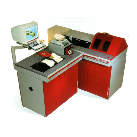
HVI 900 USTER® Instruction Manual General System Drawings Figure 1-1 HVI 900 Instrument Figure 1-2 HVI System Peripherals Uster Technologies, Inc. Chapter 1 Version 4.0 (1.99) Introduction - Page 1-2... -
Page 15: Hvi 900 System Modules
USTER® Instruction Manual HVI 900 System Modules The HVI 900 system is housed in two floor-standing cabinets: the larger cabinet contains the Length/Strength Module and the smaller cabinet contains the Micronaire and Color/Trash Modules. Included with the system are an alphanumeric keyboard, a monitor and a balance. The monitor displays the menu selections, operating instructions and test results. -
Page 16: Micronaire Module
HVI 900 USTER® Instruction Manual ♦ The comb track is now enclosed within the Length/Strength cover. To access it, lift the door located on top of the brusher and place the fibrocomb in the track. The Length/Strength start button is then pressed to initiate the measuring process, or it can be automatically prompted using the software. -
Page 17: Color/Trash Modules
This will cause the pressure plate to descend to the test tray. The HVI 900 system uses two lamps to measure a sample during testing. The two color components of cotton—reflectiveness and yellowness—... -
Page 18: Software Version 4.0 Features
Instruction Manual Software Version 4.0 Features The HVI 900 system’s version 4.0 software uses a pop-up menu structure. This allows you to select the procedures to be performed from options displayed on the screen. Once a selection has been entered, the screen reflects the choice and displays the next menu or procedure level. -
Page 19: Keyboard Commands
If the keyboard does not respond to input or if the system halts in mid- operation, reset the system (refer to Resetting the HVI 900 System in Chapter 3). If there is still no response, turn off the main power switch located on the front of the Length/Strength cover. -
Page 20: Visual Cues Used In This Manual
HVI 900 USTER® Instruction Manual • When an item requires that free-form information (values) be entered, an entry box is displayed when you press ENTER. Enter the new value(s) in the entry box using the keyboard. Avoid typos by double-checking the accuracy when you enter before information using the keyboard. -
Page 21: Special Function Keys
For the most part, the figures in this manual are screens, as they appear when you have performed the tasks discussed in that section. They represent what you see on the monitor if you have an HVI 900 with the Length/Strength, Micronaire, and Color/Trash Modules. If you have a different system configuration, the screens you see displayed on your monitor may differ. -
Page 22: Safety Warning Labels
Safety Warning Labels This section depicts examples of the warning labels used on the Version 3 HVI 900 instruments. The HVI is safe to operate in a normal manner; however, there are certain conditions that warrant cautionary statements. The following warning labels have been used to inform the operator and service personnel of the hazardous areas and conditions in the instrument. -
Page 23: Example Labels
HVI 900 USTER® Instruction Manual Example Labels 7.5.1 Micronaire and Color/Trash Cabinet This label is located behind the front and rear doors on the frame of the micronaire and color/trash cabinet. Caution should be taken to avoid pinching your hand under... - Page 24 HVI 900 USTER® Instruction Manual 7.5.2 Length/Strength Cabinet An equipment label is located on the rear enclosure (behind the rear doors). A label is located on the brushing assembly indicating where the pinch hazard could occur if your hand is in the area of the brusher.
- Page 25 HVI 900 USTER® Instruction Manual A warning label with the hand/wire/flash is located on the top of the power distribution box (control box). This indicates that hazardous voltage is under this cover. Operators should NEVER be allowed in here. This label is also located on the frame of the instrument behind each of the front and rear cabinet doors.
- Page 26 HVI 900 USTER® Instruction Manual Uster Technologies, Inc. Chapter 1 Version 4.0 (1.99) Introduction - Page 1-14...
-
Page 27: Chapter 2 Installation
USTER® Instruction Manual Chapter 2 Installation The HVI 900 System is shipped in three separate crates containing the module cabinets, peripherals, and some of the internal parts of the system. Any loss or damage should be immediately reported to the carrier. -
Page 28: Electrical Power Requirements
Electrical Power Requirements All the system components are plugged into the power strips in the back of each of the cabinets. The Version 3 HVI 900 instrument operates on 230 volts (50 to 60 Hz) and requires a separate dedicated 15-amp circuit breaker at the facility’s electrical load center. -
Page 29: Compressed Air
HVI 900 USTER® Instruction Manual The instrument must be operated in a controlled environment in the range of 20°C ±2°C (65°F to 72°F). The relative humidity should be 65%, ±2%. For consistent results, fiber samples should be conditioned in the laboratory environment. -
Page 30: Floor Space Requirements
HVI 900 USTER® Instruction Manual Floor Space Requirements The 900 SA is always installed in a straight-line configuration. The Length/Strength cabinet physically occupies a space of 137 cm (54 inches) long by 80 cm (31.5 inches) deep. The working surface is 98 cm (38.5 inches) from the floor. -
Page 31: Connections
Connect the bar code reader to the cable labeled COM2 (located in the Micronaire cabinet). The HVI 900 system is now ready for use. Allow the system to warm up for at least four (4) hours before performing calibrations for the first time. - Page 32 HVI 900 USTER® Instruction Manual Most cotton standards organizations recommend that the temperature be in the range of 20°C ±2°C (65°F to 72°F) for a testing cotton environment. The relative humidity should be 65%, ±2%. It is suggested that fiber samples be conditioned in the laboratory environment for consistent testing results.
-
Page 33: Chapter 3 System Startup
USTER® Instruction Manual Chapter 3 System Startup The HVI 900 is a sophisticated instrument that requires specific instruction and training to be used properly. Only operators that have received proper training should use the HVI system. Before beginning to use the instrument, make sure the system has been properly installed (see Chapter 2). -
Page 34: Explanation Of The Startup Menu
HVI 900 USTER® Instruction Manual Explanation of the Startup Menu The Version 4 software of the 900 SA System is installed on the hard disk drive (C:\). When the system is powered, the software performs a series of checks before it displays the S... -
Page 35: Explanation Of The Main Menu
TATUS different from those shown in this manual. The HVI 900 system name is displayed in the box at the top of the screen. The software version notation (4.0) is located in the right corner of this box. To begin using the system, highlight the selection for the operation to be performed using the arrow keys, then press the ENTER key. -
Page 36: System Testing
♦ Proceed with Testing ♦ Identifier ♦ Reset the Sample Counter Refer to Chapter 6, HVI 900 System Testing, for detailed information on the system testing procedures used for an HVI 900 system. Module Testing Module Testing should be used when only one of the Modules in the HVI system is required for testing. -
Page 37: Calibration
♦ Color ♦ Trash ♦ Temperature ♦ Relative Humidity Refer to Chapter 5, HVI 900 System Calibration, for detailed information on the calibration procedures. Diagnostics This section is used for troubleshooting and maintenance of the system. ONLY Authorized Uster Technologies Service Technicians should access this selection. -
Page 38: 940 Datamanager
♦ Edit Database Refer to Chapter 8, 940 DataManager, for instructions on using the 940 D ANAGER Synthetic Testing The HVI 900 system can be used for testing synthetic fibers. It is selected by highlighting S item and pressing the YNTHETIC IBER ENTER key. -
Page 39: Shutdown
Resetting the HVI 900 System The main purpose of resetting the HVI 900 system is to clear the software of unnecessary information. Resetting erases old values from the system's memory buffer. If the system is reset in the middle of a testing sequence, the result will be a loss of test data. - Page 40 HVI 900 USTER® Instruction Manual • The system will reset and delete any measurement values that were interrupted when the reset procedure was initiated. The S TART will appear. Uster Technologies, Inc. Chapter 3 Version 4.0 (1.99) System Startup - Page 3-8...
-
Page 41: Chapter 4 Status-Defining Parameters
HVI 900 USTER® Instruction Manual Chapter 4 Status-Defining Operating Parameters This Status chapter explains how to define a number of important operating parameters. Typically, most of the items on the S TATUS will not need to be changed after this initial installation and definition. -
Page 42: Entering Parameter Information
HVI 900 USTER® Instruction Manual Entering Parameter Information Each menu item on the S will display either the option TATUS currently selected or an arrow indicating that another menu can be accessed to display the parameter options. Each of the parameter options can be changed using any of the following methods. -
Page 43: Explanation Of The Status Menu
HVI 900 USTER® Instruction Manual Explanation of the Status Menu System Testing Results This menu item is used to indicate where the testing results are to be sent. The following options are displayed when the ENTER key is pressed. ♦ None—The test results are displayed on the screen only. -
Page 44: Grade Entry
HVI 900 USTER® Instruction Manual Highlight each item that applies by using the arrow keys and pressing the ENTER key. An arrow is displayed to the left of each selected choice. Test results can be sent to multiple locations. For example, if... -
Page 45: Trashmeter
♦ On — The Trashmeter performs a trash analysis during System Testing. Color Tray The Color Tray option is applicable to the HVI 900 Automatic only. It appears shaded (grayed out) on the HVI 900, Version 4 software. Transmission Timeout... -
Page 46: Number Of Micronaire Tests (8 Max)
HVI 900 USTER® Instruction Manual 4.10 Number of Micronaire Tests (8 max) This item is used to indicate the number of micronaire tests that are to be performed on each sample. Enter the amount using the number keypad, then press ENTER. It is recommended that only one (1) micronaire test be performed. -
Page 47: Number Of Length/Strength Tests (10 Max)
HVI 900 USTER® Instruction Manual 4.12 Number of Length/Strength Tests (10 max) This item is used to indicate the number of length and strength tests that are to be performed on each sample. Enter the amount using the number keypad, then press ENTER. It is recommended that two (2) Length/Strength Tests be performed. -
Page 48: Edit Color Chart
HVI 900 USTER® Instruction Manual 4.14 Edit Color Chart The Edit Color Chart item is used to create a new chart, modify an existing chart, or remove an existing color chart. Note: Upland cannot be modified or removed from the list. If Upland... - Page 49 HVI 900 USTER® Instruction Manual 4.14.1 Create a New Chart The D is used to select whether the lines on the chart will be ESIGN Mesh style or Slant style. ♦ Mesh Lines— The chart consists of a user-defined number of evenly spaced vertical and horizontal lines.
- Page 50 HVI 900 USTER® Instruction Manual The C will appear. To define the chart, you OLOR HART EFINE must know the number of Rd categories, number of +b categories, and the starting color grade. If you do not know or don't want to continue with the creation of the new chart, press N to answer the question at the bottom of the screen "Do you wish to continue (y/n)?"...
- Page 51 HVI 900 USTER® Instruction Manual 4.14.1.2 Creating a Slant Line Color Chart The Slant Line Color Chart consists of a series of parallel slanted lines that are not necessarily the same distance apart. The Pima chart is an example of the Slant Line-type chart.
- Page 52 HVI 900 USTER® Instruction Manual The C will appear. To define the chart, you OLOR HART ESIGN must know the number of parallel lines on the chart, the first and second Rd and b+ column numbers for each line, and the color grades for each area of the chart.
- Page 53 HVI 900 USTER® Instruction Manual The following information was used to create the Pima Chart. It can be used as a guideline for designing the Pima chart or other Slant Line-type charts. • Name of Color Chart: Type PIMA, press ENTER.
- Page 54 HVI 900 USTER® Instruction Manual 4.14.2 Modify an Existing Chart Modify an Existing Chart • Select when you want to change a chart that you have created. The chart selected is displayed on screen showing the current values. • Using the arrow keys to move the cursor, edit the data as necessary.
- Page 55 HVI 900 USTER® Instruction Manual 4.14.3 Remove an Existing Chart Color Charts can be removed (with the exception of the PIMA and Remove Existing Chart Upland charts) using the option. The color chart that is currently displayed in the Edit Color Chart field will be removed.
-
Page 56: Lot Limits
HVI 900 USTER® Instruction Manual 4.15 Lot Limits The Lot Limits menu item is used to establish a range of legitimate property values to be used during System Testing. When a sample property is measured during System Testing and it falls outside the valid Lot range, the system will produce a warning message. -
Page 57: Edit Lot Limits
HVI 900 USTER® Instruction Manual 4.16 Edit Lot Limits Edit Lot Limits • Select to create a new lot limits specification, modify an existing specification, or delete an existing specification. The name displayed on the S Lot Limits line is the one that TATUS will serve as the basis for creating a new lot limits specification. - Page 58 HVI 900 USTER® Instruction Manual 4.16.1 Create New Lot Limits The Create New Lot Limits item is used to define new lot limits. When selected, a box is displayed requesting that you enter a name for the new lot limits specification. You cannot use an existing name; the lot limits name must be unique.
- Page 59 HVI 900 USTER® Instruction Manual Lot Limits are not checked during Module Testing. 4.16.2 Determining the Action when Cotton Fails to Meet Lot Limits This selection is used to determine which retest action(s) will take place when a sample is rejected as a result of one of its properties.
- Page 60 HVI 900 USTER® Instruction Manual 4.16.3 Defining Lot Limit Color Grades If Color Grades are set to "Off," all color grades are considered to be acceptable even if a list of acceptable grades has been defined. Also, Define Grades menu item is shaded. When Color Grades is set to "On,"...
- Page 61 HVI 900 USTER® Instruction Manual Once the Lot Limits are in effect, any cotton tested during System Testing that has a color grade not included in the Acceptance list will result in Action the following question being displayed (if the field is set to "Verify."...
- Page 62 HVI 900 USTER® Instruction Manual 4.16.4 Changing Specifications for Properties The upper and lower limits for each of the fiber properties can be set or changed by highlighting the property to be changed, then pressing the ENTER key. Each property will display a Limits window where the lower and upper values can be set/changed.
- Page 63 HVI 900 USTER® Instruction Manual • Select the value to set/edit, then press ENTER. A box will be displayed where the new value should be entered. Press ESCAPE when you have completed setting/editing the values. A box will display listing the following options: ♦...
- Page 64 HVI 900 USTER® Instruction Manual 4.16.5 Modify Existing Lot Limits Modify Existing Lot Limits item is used to change a specification that has been previously created. The lot limit name currently listed on the Lot Limits line of the S is the one that will be modified.
-
Page 65: Retest Tolerances
HVI 900 USTER® Instruction Manual Expired or invalid Lot Limits can be removed from the Lot Limits list using the Delete Existing Lot Limits item. When this item is selected, a confirmation box is displayed requiring you to confirm that the selected specification is to be deleted. -
Page 66: Uster® Sci Regression Coefficients
4.18 Uster® SCI Regression Coefficients Uster® Spinning Consistency Index (SCI) is a calculated value based on multiple regression analyses that compare fiber properties to yarn properties. Each equation takes into account all HVI properties, and calculates one value to be used on each test sample. The standard equation for SCI is based on the following information. - Page 67 A screen is displayed that lists the standard values recommended by Uster Technologies, Inc. and the current values used for calculating SCI. The standard values listed in the first (left) column are the values recommended by Uster Technologies.
-
Page 68: Csp Regression Coefficients
HVI 900 USTER® Instruction Manual The Uniformity standard value will change depending on whether ICC (ratio) or HVI (index) cotton has been selected as the Calibration Mode. The Length standard value will change depending on whether English or Metric has been selected as the Length Units measuring system. The choices are shown in parentheses beside uniformity and length. - Page 69 Instruction Manual The CSP Regression Coefficients screen displays the standard values recommended by Uster Technologies, Inc. and the current values used for calculating CSP. The standard values listed in the first (left) column are those values recommended by Uster. These standard values cannot be changed and are listed so that you can compare the current values with the standard values.
-
Page 70: Temperature And Humidity Constants
HVI 900 USTER® Instruction Manual Once you have established the regression coefficient values, they should not be changed. 4.19.1 Using mN/tex Instead of CSP If you want to use mN/tex instead of CSP, enter the following coefficient values. Constant -41.02 Strength (g/tex) 0.53... -
Page 71: Company Name
HVI 900 USTER® Instruction Manual For the relative humidity and temperature probe to be activated, the R.H. & Temp item must be set to "On." If you want an alarm to sound R.H. when the relative humidity or temperature exceeds the set limits, the &... -
Page 72: Status Listing
It should be printed after initial installation and after any software updates. The Service Listing is typically used by Uster Technologies, Inc. Service Technicians to help troubleshoot any problems that you may be experiencing. - Page 73 Note: We recommend that both reports be printed after the initial installation and calibration are completed. One copy of these reports should be returned to Knoxville, with the HVI 900 Uster Technologies, System Installation Guide/Report. Another copy of the reports should be stored with the original system diskettes in a safe place.
- Page 74 HVI 900 USTER® Instruction Manual Uster Technologies, Inc. Chapter 4 Version 4.0 (1.99) Status - Page 4-34...
-
Page 75: Chapter 5 Hvi 900 System Calibration
Instruction Manual Chapter 5 HVI 900 System Calibration All measuring modules of the HVI 900 system must be calibrated prior to initial startup. After initial startup, the modules should be calibrated as calibration standards change. Calibration cottons and the standard color tiles provided with the instrument must be used to calibrate and to check calibrations. -
Page 76: Overview Of System Calibration
HVI 900 USTER® Instruction Manual Overview of System Calibration Calibration should be performed for each individual module of the HVI (Length/Strength, Micronaire and Color/Trash). Start by selecting the module item from the C . Access the C ALIBRATION ALIBRATION Calibration... -
Page 77: Length /Strength Calibration
HVI 900 USTER® Instruction Manual Note: Depending on the configuration of your instrument, the menu displayed on your screen may differ from the figure shown in this manual. Length /Strength Calibration The Length/Strength Calibration menu item is used to set the following: •... -
Page 78: Length Standard Calibration
HVI 900 USTER® Instruction Manual Length Standard Calibration The Length Standard Calibration item is used to check and update the accuracy of the value that measures the distance from the comb transport’s home position to the center of the optics. - Page 79 HVI 900 USTER® Instruction Manual • Remove your hands and other objects from the area and press ENTER to begin the test. The instrument will perform the test using the length standard and it will display the results indicating whether the value measured Passed or Failed.
- Page 80 HVI 900 USTER® Instruction Manual • After the test is complete, raise the cabinet top, and slide the metal length standard to the right along the track to remove the length standard. Lower the cabinet top to its original position.
-
Page 81: Length/Strength Setup
As described in the Appendix, Calibration Cottons for the Uster Technologies HVI 900 System, calibration is performed following engineering principles using hardware devices. Adjustments are then made within the instrument to the unadjusted, raw values through software manipulations. - Page 82 HVI 900 USTER® Instruction Manual Adjusting the values is accomplished by two-point regression analysis of individual test data points. The mathematics of the simple regression will show relationships defined by “slopes” and “offsets.” If, by chance, the unadjusted values of the instrument tests agree exactly with the designated values of the two-calibration cottons, the software “slope”...
- Page 83 HVI 900 USTER® Instruction Manual 4.6.1 Calibration for Short Cotton The Calibration for Short Cotton is performed first. The standard values of the calibration cotton are displayed in the middle of the screen. The lower section of the screen displays the procedure's instructions. It also displays the sample counter (XX of 12 samples) and the constantly updated instrument readings on optics and force.
- Page 84 HVI 900 USTER® Instruction Manual Note: If the size of the sample beard is too large or small for the measurement mechanisms, an error message saying "Large Sample" or "Small Sample" will be displayed. When either of these messages appears, simply perform another repetition.
- Page 85 HVI 900 USTER® Instruction Manual • Check that the standard values for Long Cotton displayed on the screen are the same as the values on the box of Long Cotton being used for calibration. • Perform Test 1 of 12 for Long Cotton. Repeat the steps for testing Short Cotton using the Long Cotton, rotating and exchanging the cottons in the same order.
- Page 86 HVI 900 USTER® Instruction Manual If all parameters are within the tolerance levels (passed), the instrument is properly calibrated. The L will ENGTH TRENGTH ALIBRATION reappear when the ENTER key is pressed 4.6.3 Cotton Calibration Test Results—Fail Condition If there is a difference of one or more between the Standard Values and Average measured values that exceeds the Tolerance values, a "Fail"...
-
Page 87: Calibration Mode
HVI 900 USTER® Instruction Manual ♦ The chosen tolerance value may not be realistic when consideration is given to the fact that cotton, even calibration cotton, is variable. If a "Fail" condition exits, the Cotton Calibration for Short Cotton Screen reappears, and 12 more tests for short cotton must be performed until all samples pass. -
Page 88: Length Units
HVI 900 USTER® Instruction Manual Length Units This selection alternates between English (inches) and Metric (millimeters). ♦ English — The reporting units are in inches. ♦ Metric — The reporting units are in millimeters. The software automatically changes the regression coefficient length value for the Length Units selected. -
Page 89: Icc Sl2
HVI 900 USTER® Instruction Manual 4.10 ICC SL2% The cotton industry has chosen 2.5 % for the ICC mode. When this item is selected, an instruction line is displayed on the screen where a value for ICC SL2 % should be entered. You many enter a value other than 2.5 percent, if appropriate. -
Page 90: Calibration Constants
HVI 900 USTER® Instruction Manual 4.11 Calibration Constants To access Calibration Constants from the C ALIBRATION TATUS highlight the item using the arrow keys, then press ENTER. Slope and offset values for uniformity, length, strength, elongation, and S.F. are entered from the C . -
Page 91: Calibration Cotton Standard Values
HVI 900 USTER® Instruction Manual 4.12 Calibration Cotton Standard Values • To access Calibration Cotton Standard Values from the C ALIBRATION , highlight the item using the arrow keys, then press TATUS ENTER. They should be set based on the values that are listed on the boxes of calibration cottons currently in use. -
Page 92: Calibration Check Tolerances
HVI 900 USTER® Instruction Manual 4.13 Calibration Check Tolerances • To access Calibration Check Tolerances from the C • To access Calibration Check Tolerances from the C ALIBRATION ALIBRATION TATUS TATUS , highlight the item using the arrow keys, then press ENTER. -
Page 93: Calibrating For Micronaire
HVI 900 USTER® Instruction Manual Calibrating for Micronaire The calibration procedure for micronaire involves the regulation of airflow through the micronaire chamber when 10.0-gram samples of cotton with low and high micronaire values are in the chamber. • To access the M... -
Page 94: Micronaire Cotton Calibration
HVI 900 USTER® Instruction Manual Micronaire Cotton Calibration Cotton Calibration Select the item from the M using the ICRONAIRE arrow keys, then press ENTER. On-screen instructions for testing samples of low- and high-value calibration cottons lead you through the calibration procedure. - Page 95 HVI 900 USTER® Instruction Manual • The test is automatically performed, the lid opens, and the sample is ejected from the chamber. The screen displays the mass for the sample. • Weigh the sample of high-micronaire cotton, and place it in the chamber.
-
Page 96: Air Calibration
HVI 900 USTER® Instruction Manual Air Calibration Air Calibration typically is only used if an error occurs during cotton calibration. In such cases, first check to make certain the correct cotton was used. Next, check that the cotton values on the box match the values in the system. -
Page 97: Micronaire Status Menu
HVI 900 USTER® Instruction Manual Micronaire Status Menu The Micronaire Status Menu is used to enter the low and high cotton standard values, the slope, offset, default slope, and offset values. Micronaire Status • Select the item from the M... -
Page 98: Calibrating For Color
HVI 900 USTER® Instruction Manual Calibrating for Color • To access the C from the C OLOR ALIBRATION ALIBRATION highlight the item using the arrow keys, then press ENTER. The calibration procedure for the color testing mechanism is simple. The... -
Page 99: Color Calibration
HVI 900 USTER® Instruction Manual Color Calibration The steps listed below outline the procedure for calibrating color for the first time. Color Calibration • Select the item from the C OLOR ALIBRATION using the arrow keys, then press ENTER. The standard Rd and +b values for each color tile are displayed. An arrow points to the White tile and an instruction statement is displayed requesting that the white tile be placed on the color window. - Page 100 HVI 900 USTER® Instruction Manual Always use the same set of tiles for daily calibration that were used for the initial color calibration. Do not mix tile sets. 6.4.1 Steps for Tile Calibration • Remove the requested tile from the box of tiles supplied with the instrument.
-
Page 101: Standard Tile Values
HVI 900 USTER® Instruction Manual Standard Tile Values • To access the S , highlight the item from the TANDARD ALUES , then press ENTER. OLOR A window is displayed listing each color tile with its Rd and +b values. -
Page 102: Rd And +B Tolerance
HVI 900 USTER® Instruction Manual Rd and +b Tolerance • To access the R from the C D AND OLERANCE ALIBRATION , highlight the item using the arrow keys, then press ENTER. This item is used to enter the tolerance values for the Rd and +b. These values are used to determine the Pass/Fail during color calibration. -
Page 103: Calibrating For Trash
HVI 900 USTER® Instruction Manual Calibrating for Trash • To access the T from the C RASH ALIBRATION ALIBRATION Trash highlight the item using the arrow keys, then press ENTER. This menu has selections for performing Tile and Sample Calibration, for entering the Tile Area and Tile Count values, the Number of Samples, the Starting Sample Code, and for Trash Setup. -
Page 104: Starting Sample Code And Number Of Samples
HVI 900 USTER® Instruction Manual Starting Sample Code and Number of Samples The number entered for Number of Samples determines how many samples the software will request to test during Sample Calibration. The Starting Sample Code should be the code for the first sample to be viewed during Sample Calibration. -
Page 105: Tile Calibration
HVI 900 USTER® Instruction Manual Tile Calibration • To access the T from the T , highlight ALIBRATION RASH the item using the arrow keys, then press ENTER. • Place the requested trash calibration tile on the window and press the color/trash button(s). -
Page 106: Sample Calibration
HVI 900 USTER® Instruction Manual Sample Calibration • To access the S from the C AMPLE ALIBRATION ALIBRATION highlight item using the arrow keys, then press ENTER. • Place the first sample on the window, and press the color/trash button(s). The hand will descend, the sample will be viewed, and the hand will lift. -
Page 107: Trash Setup
Instruction Manual Trash Setup This selection is for service technicians only. None of the information displayed on this screen should be altered, except by authorized Uster Technologies personnel. When this selection is chosen a warning message is displayed. When you press a key, the warning message is cleared from the screen,... -
Page 108: Trend Calibration
HVI 900 USTER® Instruction Manual Temperature • To calibrate for Temperature, select the item using arrow keys, then press ENTER. The T EMPERATURE ALIBRATION is displayed. Follow the same procedures discussed below for calibrating for Relative Humidity. From this menu you can calibrate temperature by Trend Calibration. You can see the current value or set the current value when you have a reasonably good value for the slope. - Page 109 HVI 900 USTER® Instruction Manual • Enter the number of trend points to be used (between 2 and 10). The screen provides entry points for the desired and current value for each of the points. As each value is entered, the cursor moves to the next entry.
-
Page 110: Set Current Value
HVI 900 USTER® Instruction Manual Set Current Value An entry box is displayed to enter the current temperature. When this selection is used, only one point is used to adjust the slope from the current value. The slope must be reasonably correct when this selection is used. -
Page 111: Chapter 6 Hvi 900 System Testing
The 940 DataManager collects, sorts, and stores data received from the HVI 900 instruments. It is used to export selected test data, as well as edit the database. Each user can determine how the fiber test results will be arranged, sorted, and stored for review and interpretation. -
Page 112: Overview Of Testing Sequence
The Color Tray Arm returns to its resting position and repeats the process the number of repetitions specified by the S TATUS Uster Technologies, Inc. Chapter 6 Version 4.0 (1.99) HVI 900 System Testing - Page 6-2... - Page 113 HVI 900 USTER® Instruction Manual ° Discard the cotton sample. Uster Technologies, Inc. Chapter 6 Version 4.0 (1.99) HVI 900 System Testing - Page 6-3...
- Page 114 Chapter 4.) If, according to the selections made on the , the results are to be sent to a printer and/or external TATUS computer, they are then transmitted. Uster Technologies, Inc. Chapter 6 Version 4.0 (1.99) HVI 900 System Testing - Page 6-4...
-
Page 115: Explanation Of The Sign-On Menu
System Testing Screen. If no Identifier has been entered, an entry Identifier box will display where the should be entered (when test results are to be sent to a printer or an external computer). Uster Technologies, Inc. Chapter 6 Version 4.0 (1.99) HVI 900 System Testing - Page 6-5... -
Page 116: Identifier
The data required for the information fields on the System Testing screen depend on the way the system was set up using the S (see Chapter 4). TATUS Uster Technologies, Inc. Chapter 6 Version 4.0 (1.99) HVI 900 System Testing - Page 6-6... - Page 117 The box in the bottom right of the screen will display various messages that involve the external computer system, retests, lot limits, rejecting sample test results, and leaving System Testing. Uster Technologies, Inc. Chapter 6 Version 4.0 (1.99) HVI 900 System Testing - Page 6-7...
-
Page 118: Grade
If you do not want to store/use the grade code information, the field can be used to enter other relevant information you want to keep on each sample. Uster Technologies, Inc. Chapter 6 Version 4.0 (1.99) HVI 900 System Testing - Page 6-8... -
Page 119: Leaf, Area % And Count
+b values. Color Grade The color grade is represented by up to four (4) alphanumeric characters from the USDA, Upland, Pima, or user-defined color charts. Uster Technologies, Inc. Chapter 6 Version 4.0 (1.99) HVI 900 System Testing - Page 6-9... -
Page 120: Micronaire (Mic)
0.5 of an inch. This estimated percentage is referred to as short fiber index (SFI). SFI correlates to the short fiber content as measured by Suter-Webb data or AFIS. Uster Technologies, Inc. Chapter 6 Version 4.0 (1.99) HVI 900 System Testing - Page 6-10... -
Page 121: Samples
(refer to the section, How to Exit from System Testing, in this chapter). Uster Technologies, Inc. Chapter 6 Version 4.0 (1.99) HVI 900 System Testing - Page 6-11... -
Page 122: Sample Testing Procedures
If you will never be entering information in the field, the S TATUS selection should be changed to "NO" so that the cursor will not stop on the Grade field. Uster Technologies, Inc. Chapter 6 Version 4.0 (1.99) HVI 900 System Testing - Page 6-12... -
Page 123: Measurement Procedures For Micronaire
MIC line of the test display. You can change the mass of the sample after the weight is displayed on the monitor; however, the software uses the last acceptable mass for calculating the micronaire value. Uster Technologies, Inc. Chapter 6 Version 4.0 (1.99) HVI 900 System Testing - Page 6-13... - Page 124 Note: If this message appears repeatedly, it could mean there is an air leak in the micronaire chamber. In such case, contact an Uster Technologies service technician. Uster Technologies, Inc.
-
Page 125: Measurement Procedures For Color/Trash
+b value is <4 or >18, the message "Invalid Color" is displayed, even if lot limits are not set. If this occurs, the color test must be repeated. Uster Technologies, Inc. Chapter 6 Version 4.0 (1.99) HVI 900 System Testing - Page 6-15... - Page 126 The Leaf Code test results are displayed on the Leaf line, the Area % on the next line, and the trash Count on the following line. Property Name Valid Results Area % 0 to 5% Count 0 to 999 Uster Technologies, Inc. Chapter 6 Version 4.0 (1.99) HVI 900 System Testing - Page 6-16...
-
Page 127: Testing Procedures For Length, Uniformity, Strength, And Elongation
The comb is pushed onto the metal tray to the far left of the console when the next sample is tested. Uster Technologies, Inc. Chapter 6 Version 4.0 (1.99) HVI 900 System Testing - Page 6-17... - Page 128 Length/Strength and Fineness test results and that an identification number (ID) must be entered before the test results are printed or transmitted. Uster Technologies, Inc. Chapter 6 Version 4.0 (1.99) HVI 900 System Testing - Page 6-18...
-
Page 129: Exit From Testing
The messages displayed in this box vary depending on whether the test results are sent to a printer or to the printer and external computer. Uster Technologies, Inc. Chapter 6 Version 4.0 (1.99) HVI 900 System Testing - Page 6-19... - Page 130 If you press ESCAPE too soon, you will lose test results that have not been transmitted and must repeat all tests on that sample to regain the results. Uster Technologies, Inc. Chapter 6 Version 4.0 (1.99) HVI 900 System Testing - Page 6-20...
-
Page 131: Printing The Test Results
4 0.65 0.93 1.11 84.0 5.8 27.0 5.9 4.8 70.7 8.9 42- 45769 43 4 0.68 0.91 1.09 83.4 6.8 25.0 5.8 4.8 71.0 9.3 42- Uster Technologies, Inc. Chapter 6 Version 4.0 (1.99) HVI 900 System Testing - Page 6-21... - Page 132 Lightness (% of Reflectance) entry Yellowness (on Hunter's scale) Color test results Color Grade (Upland, Pima, or User Color test results Defined) Color test results Printout Interpretation Uster Technologies, Inc. Chapter 6 Version 4.0 (1.99) HVI 900 System Testing - Page 6-22...
-
Page 133: System Testing Diagnostics
— Sequence error* Comb to Break — Waiting on motor to complete movement Strength Interrupt — Waiting on strength data — Clamp sensors not functional Uster Technologies, Inc. Chapter 6 Version 4.0 (1.99) HVI 900 System Testing - Page 6-23... - Page 134 * A sequence error means that one of the computers has gone to its next step before receiving permission from the other computer. If this occurs, reset the system. Uster Technologies, Inc. Chapter 6 Version 4.0 (1.99) HVI 900 System Testing - Page 6-24...
- Page 135 HVI 900 USTER® Instruction Manual Uster Technologies, Inc. Chapter 6 Version 4.0 (1.99) HVI 900 System Testing - Page 6-25...
-
Page 136: Chapter 7 Module Testing
HVI 900 USTER® Instruction Manual Chapter 7 Module Testing Module Testing Menu The purpose of Module Testing is to test individual samples outside the normal System Testing sequence. Module Testing can be performed for Length/Strength, Micronaire, and Color/Trash. Because each test is... -
Page 137: Length/Strength Module Testing
HVI 900 USTER® Instruction Manual Length/Strength Module Testing • To access Length and Strength Module testing from the M ODULE Length & Strength , use the arrow keys to highlight , then press ENTER. The L is used to make any... - Page 138 HVI 900 USTER® Instruction Manual 3.4.2 Identifier The Identifier field is used to enter an identification number that defines the lot or merchant number for a particular group of samples. This identifying information should be entered when test results are to be...
- Page 139 HVI 900 USTER® Instruction Manual 3.4.4 Micronaire Data This selection is used to indicate how the micronaire value will be entered. It alternates between None, Micronaire, and Keyboard. Use the ENTER key to toggle between options. • None — No micronaire value will be entered. The system default micronaire value of 4.0 will be used whenever a micronaire value is...
- Page 140 HVI 900 USTER® Instruction Manual 3.4.6 Printer This selection is used to indicate whether the test results will be sent to a printer. It alternates between No and Yes using the ENTER key. • No — Test results are not sent to the printer.
- Page 141 HVI 900 USTER® Instruction Manual 3.4.8 Graph Mode The Graph Mode option is used to indicate if and what type of graph should be printed to display the test results. The following options can be selected: • Fibrogram — The average fibrogram will be printed. The test data is printed on one page and the fibrogram on the next page.
- Page 142 HVI 900 USTER® Instruction Manual • Individual Observations - Data on the individual observations for each module will be transmitted. For example, if the system is set up to perform two Length/Strength tests, one Micronaire test, and four Color/Trash tests, the data for each of these seven tests will be transmitted.
- Page 143 HVI 900 USTER® Instruction Manual • Mean Fibrogram Curves - The data points that make up the fibrogram for the mean of all observations will be transmitted. • Mean Stress/Strain Curves - The data points that make up the Stress/Strain Curve for the mean of all observations will be transmitted.
- Page 144 HVI 900 USTER® Instruction Manual 3.4.11 Reject Sample to Computer/ DataManager When the test results for the last sample tested should be rejected, Reject Sample to ESCAPE from the Module Testing Screen, and select Computer/ DataManager . This sends a signal to the external computer and/or to DataManager that the previous sample tested is to be rejected.
-
Page 145: Explanation Of The Length/Strength Module Testing
HVI 900 USTER® Instruction Manual 3.4.12 Sign Off External Computer When this is selected, a signal is sent to the external computer that the current Identifier is to be closed. Use this selection to close out a lot when testing is completed for the day. -
Page 146: Length/Strength Module Testing Procedures
HVI 900 USTER® Instruction Manual The Optics and Force values, as well as the Temperature and Relative Humidity values, are continuously updated and displayed at the bottom of the screen. Length/Strength Module Testing Procedures • If test results will be sent to a printer or transmitted to a host computer, an ID must be entered on the test screen. - Page 147 Using the Fibrosampler, make the sample comb and then place it on the track. Refer to the Length/Strength test procedures in Chapter 6, 900 HVI 900 System testing, for further details. • When the tests have been completed, the results are displayed on the Length/Strength Module Testing Screen.
- Page 148 HVI 900 USTER® Instruction Manual 3.6.1 Exiting Length/Strength Module Testing When you are finished with Length/Strength Module Testing use the following steps to exit the screen. • After a test series is complete, a blank Test Results Screen is displayed requesting that you either "Enter ID" or supply the micronaire value (if required).
-
Page 149: Micronaire Module Testing
HVI 900 USTER® Instruction Manual Micronaire Module Testing Micronaire Module Testing Menu • To access the M from the M ICRONAIRE ODULE ESTING ODULE Micronaire , highlight , then press ENTER. The M is used to make any necessary ICRONAIRE... - Page 150 HVI 900 USTER® Instruction Manual 4.4.2 Identifier This information is not required and may already be provided if the ID Continue was entered during another module test. You can proceed to with Testing without entering information in the Identifier field.
- Page 151 HVI 900 USTER® Instruction Manual 4.4.5 External Computer This selection determines whether or not the test results will be sent to an external computer system via a serial cable. It alternates between OFF and ON using the ENTER key. • OFF — The test results will not be transmitted to an external computer system.
- Page 152 HVI 900 USTER® Instruction Manual • Means - The mean value of the total number of tests for each module will be transmitted. Using the example above, the mean value of the two Length/Strength tests would be transmitted rather than individual data for each (two) Length/Strength test.
- Page 153 HVI 900 USTER® Instruction Manual 4.4.7 Sign Off External Computer When this is selected, a signal is sent to the external computer that the current Identifier is to be closed. Use this selection to close out a lot when testing is completed for the day.
-
Page 154: Explanation Of Micronaire Module Testing Screen
HVI 900 USTER® Instruction Manual Explanation of Micronaire Module Testing Screen • To begin the Micronaire Module testing sequence, select the Continue with Testing from the M ICRONAIRE ODULE ESTING Then, press ENTER. Uster Technologies, Inc. Chapter 7 Version 4.0 (1.99) -
Page 155: Micronaire Testing Procedures
HVI 900 USTER® Instruction Manual The Micronaire Module Testing screen will appear. This screen differs from the one used for System Testing in that the module testing screen displays the results for each test, as well as the average of all the tests for each sample. - Page 156 HVI 900 USTER® Instruction Manual • Weigh the sample on the balance. The sample must weigh between 8.5 and 11.5 grams. When the sample is within the valid weight range, the air is turned on, and the sample weight is displayed on the screen.
-
Page 157: Color/Trash Module Testing
HVI 900 USTER® Instruction Manual Color/Trash Module Testing Color/Trash Module Testing Menu To access Color and Trash Module Testing from the M ODULE Color & Trash highlight , then press ENTER. 5.4.1 Continue with Testing This selection displays the Color and Trash Module Testing Screen. - Page 158 HVI 900 USTER® Instruction Manual 5.4.2 Identifier This information is not required and may already be provided if the ID Continue was entered during another module test. You can proceed to with Testing without entering information in the Identifier field.
- Page 159 HVI 900 USTER® Instruction Manual 5.4.5 Printer This selection alternates between Off, On, and Averages using the ENTER key. • Off — No test results will be sent to the printer; the information will only be displayed on the screen.
- Page 160 HVI 900 USTER® Instruction Manual 5.4.8 External Computer This selection determines whether or not the test results will be sent to an external computer system via a serial cable. It alternates between OFF and ON using the ENTER key. • OFF — The test results will not be transmitted to an external computer system.
- Page 161 HVI 900 USTER® Instruction Manual • Means - The mean value of the total number of tests for each module will be transmitted. Using the example above, the mean value of the two Length/Strength tests would be transmitted rather than individual data for each (two) Length/Strength test.
- Page 162 HVI 900 USTER® Instruction Manual 5.4.10 Sign Off External Computer When this is selected, a signal is sent to the external computer that the current Identifier is to be closed. Use this selection to close out a lot when testing is completed for the day.
-
Page 163: Explanation Of The Color/Trash Module Test Screen
HVI 900 USTER® Instruction Manual Explanation of the Color/Trash Module Test Screen If you entered an Identifier on the C OLOR RASH ODULE ESTING it is displayed on the top line of the Color/Trash Module Test Screen. A color test is always performed on each sample and the test results displayed in the Rd, +b, and Color Grade columns. -
Page 164: Color/Trash Module Testing Procedures
HVI 900 USTER® Instruction Manual Color/Trash Module Testing Procedures • If an ID is required (because the data will be printed or transmitted), enter up to 12 alphanumeric characters for the bale identification number via the keyboard or scanner. Be sure the number is entered correctly, and then press ENTER. - Page 165 HVI 900 USTER® Instruction Manual • When the required number of tests has been completed, the average (AVG) is displayed. The standard deviation is displayed if the number of tests is five or more. After pressing ENTER to accept the test results, the screen is cleared of the test results and the data is printed and transmitted if required.
- Page 166 HVI 900 USTER® Instruction Manual Uster Technologies, Inc. Chapter 7 Version 4.0 (1.99) Module Testing - Page 7-31...
-
Page 167: Chapter 8 940 Datamanager
Chapter 8 940 DataManager The 940 DataManager collects, sorts, and stores data received from the HVI 900 instruments. It is used to export selected test data, as well as edit the database. Each user can determine how the fiber test results will be arranged, sorted, and stored for review and interpretation. -
Page 168: Categories
HVI 900 USTER® Instruction Manual Categories One of the methods of analyzing data and warehousing cotton for spinning is by Category. If this is the method you use, the Categories should be defined before utilizing the 940 DataManager. The Reports and Histograms that are generated by the 940 DataManager use these Category definitions. -
Page 169: Category Definition Screen
Categories. The screen below shows the initial category values that are shipped from the Uster Technologies factory. If you are unsure what values should be entered for a Category Definition to reflect the range of your cotton, refer to the Appendix chapter of this manual for instructions on how to determine this information. -
Page 170: Interval
HVI 900 USTER® Instruction Manual Interval This is the range or width between Categories. 940 DataManager uses intervals to determine where each Category begins and ends. Sample test results are assigned to Categories according to where they fit in the Categories. - Page 171 Each property has an Category Definition (shown in the screen above) that was set up at the Uster Technologies factory. This definition most likely does not correctly represent your inventory. Therefore, follow the instructions in the Appendix section to define your Categories.
-
Page 172: Reports
HVI 900 USTER® Instruction Manual Reports Overview This section is used to design and generate reports to be displayed on the screen or printed on the system printer. These reports contain a variety of information according to your specifications for identifiers, properties, and report types. - Page 173 HVI 900 USTER® Instruction Manual For example, reports generated by category require fewer character spaces; therefore, more properties can be selected. The property list can be divided into separate parts, and two reports can be generated if you must have all fiber properties listed by category and by value. If the report is generated by values and categories, more character spaces are required to report data for each property.
-
Page 174: Report Header Abbreviations
HVI 900 USTER® Instruction Manual Report Header Abbreviations The following is a list of the abbreviations used in the header for the fiber properties. Grade Grade Spinning Consistency Index Micronaire Strength Length Length Uniformity Short Fiber Index Elongation Trash Trash Count... -
Page 175: Selecting The Identifier(S) To Appear On The Report
HVI 900 USTER® Instruction Manual Selecting the Identifier(s) to Appear on the Report Reports are generated by the sample Identifier. Identifier • When you highlight and press ENTER, the Identifier window is displayed with all the identifiers that are stored in 940 DataManager. - Page 176 HVI 900 USTER® Instruction Manual If you selected only one identifier, that identifier name is displayed to the right of Identifier. If multiple identifiers are to be used for the Report, an arrow is displayed on the Identifier line. If you selected Identifiers, "All Identifiers"...
-
Page 177: Selecting Fiber Properties To Appear On The Report
HVI 900 USTER® Instruction Manual Selecting Fiber Properties to Appear on the Report The information that appears on the report is determined by the properties chosen. A list containing all the available fiber properties is displayed in a window. • Highlight the items to be included on the report using the arrow keys, then press ENTER. -
Page 178: Limits To Selecting Properties
HVI 900 USTER® Instruction Manual Limits to Selecting Properties If the report is to be displayed on the screen as opposed to being printed, the size of the screen limits the number of properties that can be displayed on one line (maximum of 79 characters). - Page 179 HVI 900 USTER® Instruction Manual The R will reappear where the type of report that is After EPORTS you have chosen all of the properties that are to appear on the report, press ESCAPE to save the information and return to the R EPORTS Property selections remain the same until they are changed.
-
Page 180: Tests Included On The Report
HVI 900 USTER® Instruction Manual 4.10 Tests Included on the Report When the report is generated, it can include: • Accepted Tests—Only tests that are acceptable according to the Lot Limit specification at test time will be included in the report. -
Page 181: Selecting The Destination For The Report
HVI 900 USTER® Instruction Manual 4.11 Selecting the Destination for the Report Reports can be generated for two destinations: • Screen—The report will be displayed on the screen. Up to 78 characters and spaces can be displayed per line. • Printer—A report that is printed is limited to 131 characters. If the number of characters for your selections exceeds 131, a warning message is displayed on the screen. - Page 182 HVI 900 USTER® Instruction Manual The current time, date, company name, Identifier, relative humidity and temperature (if available), and report properties are in the report header. The tests and the data for the report properties are listed for each identifier. An average of the data for the tests is calculated and displayed/printed at the end of the ID list.
- Page 183 HVI 900 USTER® Instruction Manual 4.12.2 Report Generated to Printer Make Report • Before selecting , ensure that the printer is Epson compatible, ON, on-line, and has paper inserted properly. The report will automatically generate based on your report criteria with the Lot Limit Rejections underlined and in bold print.
-
Page 184: Histograms
HVI 900 USTER® Instruction Manual Histograms Overview Histograms can be plotted for one or for multiple identifiers for a particular fiber property. • Select the identifier(s) and the property to be plotted, then choose Make Histogram Select Identifier The identifiers for the most recently completed tests are listed first (reverse chronological order). -
Page 185: Property
HVI 900 USTER® Instruction Manual When multiple identifiers are on the list, the last entry will be " Identifiers ." When it is selected, the entire list of identifiers will be included in the report. • Select the Identifier(s) that should be included in the report (up to 10) using the arrow keys to highlight the item, then press the ENTER key. -
Page 186: Make Histogram
HVI 900 USTER® Instruction Manual Make Histogram Make Histogram When you select , the parameters selected will be used to compose the histogram, which will display on the monitor. The category numbers and category midpoints for the property being plotted appear on the Y-axis in ascending order. -
Page 187: Data Export
The 940 DataManager can be used to export test data from the database in a format that is suitable for other computers. This is useful for moving test data to the Uster Technologies BIAS program or to your mainframe. • Fiber Property values can be exported for one or multiple identifiers... -
Page 188: Test Included When Data Is Exported
HVI 900 USTER® Instruction Manual all the identifiers. Use the Page Up and Page Down keys to display different pages (screens) of identifiers. When multiple identifiers are on the list, the last entry will be " Identifiers ." When it is selected, the entire list of identifiers will be included in the report. -
Page 189: Destination For Exported Files
HVI 900 USTER® Instruction Manual Destination for Exported Files A window containing a list of the three options for exporting data is displayed. • Use the Arrow keys to highlight your choice, then press ENTER. The selected choice is displayed to the right of Destination on the D XPORT Uster Technologies, Inc. - Page 190 HVI 900 USTER® Instruction Manual 6.7.1 User-Named Disk File • To enter the name of the file where data will be exported, select User-Named Disk File and press ENTER. A window is displayed where the filename (and path, if required) should be entered (e.g., if you want the exported data to be stored in a...
- Page 191 HVI 900 USTER® Instruction Manual 6.7.2 Identifier-Named Disk File Data for each identifier that has been selected will be exported to a separate file. The filename(s) will be the same as the identifier name(s). • If you want to use the identifier as the filename when data is...
-
Page 192: Communications Settings
HVI 900 USTER® Instruction Manual Communications Settings If 940 DataManager is stored on one computer and you want to move the data to another computer, you must make sure that the communications settings are configured so that the computers can understand one another. - Page 193 HVI 900 USTER® Instruction Manual communications port • Select the to be used for exporting data. After making your selection, press ENTER. The C will reappear, and the selected OMMUNICATIONS communications port will be listed to the right of Port.
- Page 194 HVI 900 USTER® Instruction Manual 6.8.3 Protocol Protocol is a set of rules that defines how computers communicate with each other when they transmit and receive data. A window is displayed with the following options: • No Parity, 8 Data, 1 Stop...
-
Page 195: Export Data
HVI 900 USTER® Instruction Manual Export Data The identifier and ID for each test that is being exported is displayed on the screen in a window labeled Export Progress. When the export process is complete, the window closes and the D XPORT displayed. -
Page 196: Add Test Data To The Database
HVI 900 USTER® Instruction Manual Add Test Data to the Database If you have test data from a sample and want to add it to an existing identifier or create a new identifier for the data, you can do this without re-testing the sample. - Page 197 HVI 900 USTER® Instruction Manual 7.4.1 Add an ID to a Currently Existing Identifier To add a test (ID) to a currently existing identifier, follow these steps. • Enter the identifier name exactly as it is in the database. Enter a new ID and all the test information.
-
Page 198: Change Test Data In The Database
HVI 900 USTER® Instruction Manual Change Test Data in the Database This selection provides a mode for changing specific test data. Change • Highlight from the selection window and press ENTER. The Identifier window is displayed on the screen. All fiber property values can be changed;... -
Page 199: Remove Test Data From The Database
HVI 900 USTER® Instruction Manual Remove Test Data from the Database This selection provides a mode for deleting data from the database. Remove • Highlight from the selection window and press ENTER. Tests can be removed from an identifier by one of two methods: •... - Page 200 HVI 900 USTER® Instruction Manual A confirmation window is displayed for each identifier that was selected. • Press "Y" to delete an identifier and all its associated tests, or press "N" to abort the deletion process without deleting the identifier.
-
Page 201: Chapter 9 Hvi Applications
HVI 900 USTER® Instruction Manual Chapter 9 HVI Applications HVI Applications The HVI can be used in a variety of applications in the cotton industry. Some of these applications are listed below. Cotton Seed Breeders — Verify progress in attaining goals in development of new varieties of cotton. -
Page 202: Importance Of Testing Fiber
Research conducted by Cotton Incorporated (USA) and Uster Technologies indicates the influence of HVI measured fiber properties on yarn strength. When spinning a Ne 26, one can see that length, length uniformity, strength, and micronaire predict over 75% of possible variation in yarn strength. -
Page 203: Applications Of Hvi Results For Spinning Mills
HVI 900 USTER® Instruction Manual Applications of HVI Results for Spinning Mills The speed of the HVI instrument allows every bale of cotton to be tested. The challenge then becomes how to effectively use the information to improve the spinning process. All cotton has a natural variation of fiber properties. - Page 204 HVI 900 USTER® Instruction Manual The next graph shows the influence of yarn strength, as well as yarn strength CV%, on the weaving end breaks. Higher speed weaving machines need yarn that is not only stronger but also yarn that has a better yarn strength CV%.
- Page 205 HVI 900 USTER® Instruction Manual Ring Spinning Rotor Spinning Uster Technologies, Inc.. Chapter 9 Version 4.0 (1.99) HVI Applications - Page 9-5...
-
Page 206: Influence Of Staple Length And Yarn Strength
HVI 900 USTER® Instruction Manual Influence of Staple Length and Yarn Strength Textile research further indicates that as cotton staple length increases so does the strength of the resulting yarn. Generally, longer staple cottons tend to be finer, thereby allowing a greater number of fibers per cross- section in yarn. -
Page 207: Influence Of Micronaire And Yarn Strength
HVI 900 USTER® Instruction Manual Influence of Micronaire and Yarn Strength Textile research indicates that micronaire influences the amount of fibers per cross-section, thereby affecting yarn strength. Generally, lower micronaire fibers are smaller in perimeter, and thus finer, allowing more fibers per cross-section. -
Page 208: Weaving Efficiency
HVI 900 USTER® Instruction Manual Weaving Efficiency The efficiency of weaving is affected by the speed of modern looms. The attached graph indicates a Picks Per Minute (PPM) increase from 300 to 600. This results in a decrease in overall efficiency from 95.5 % to 91.0 %. -
Page 209: Using Hvi Cotton Merchandising
HVI 900 USTER® Instruction Manual Using HVI Cotton Merchandising Invention of Fiber Testing Instruments During the 1940’s, several innovations in fiber instrumentation were developed. These include the micronaire, which estimates fineness; the Spinlab Hunter-Nickerson Cotton Colormeter; the Pressley and Spinlab Stelometer, which estimates fiber strength;... - Page 210 HVI 900 USTER® Instruction Manual The Liverpool Cotton Association Circular reports world cotton by its variety, grade, and staple length. Most spinning mills purchase cotton by variety, staple length, and trash content – usually in that order of importance. By segregating the bales within a variety based on staple length, one gains vital knowledge of fiber length.
-
Page 211: Example Of The Fibrograph Used By A Merchant
HVI 900 USTER® Instruction Manual Example of the Fibrograph Used by a Merchant Fifty bales (one lot) of cotton were spot purchased at a gin by a merchant. One to two bales of this lot were visually checked and identified to be an MCU-5 variety, fine grade with a staple length of 31 mm (1 ¼”). - Page 212 HVI 900 USTER® Instruction Manual Uster Technologies, Inc.. Chapter 9 Version 4.0 (1.99) HVI Applications - Page 9-12...
-
Page 213: Chapter 10 Synthetic Fiber Testing
HVI 900 USTER® Instruction Manual Chapter 10 Synthetic Fiber Testing The Synthetic Fiber Testing mechanism for the HVI 900 SA is accessed Synthetic Fiber Testing by selecting from the M As it is selected, the Motor Controller information window is displayed, and a series of tests is performed. - Page 214 HVI 900 USTER® Instruction Manual Generally, when testing synthetic fibers on the HVI, strength and elongation measurements are used to determine whether or not quality has been maintained. Calibration for synthetic fibers differs from calibration for cotton in two ways.
-
Page 215: Length/Strength Setup
MUST BE DONE PRIOR TO CALIBRATING FOR COTTON/SYNTHETIC FIBERS. Cotton/Synthetic Fiber calibration is invalid if the Length Standard or Lens to Break values are modified. Contact an authorized Uster Technologies Service Technician to perform these setup features if necessary. Synthetic Fiber Calibration... -
Page 216: Length Standard Calibration Menu
HVI 900 USTER® Instruction Manual Length Standard Calibration Menu • Use the arrow keys to highlight the L ENGTH TANDARD ALIBRATION item from the S , then press ENTER. YNTHETIC IBER Note: The metal length standard must always be entered in inches even though the fiber measurements may be made in millimeters. - Page 217 HVI 900 USTER® Instruction Manual In typical daily operation, the metal standard does not need to be used. It should only be done when there is a Fail situation in the Calibration procedure every time a test is performed. 3.5.1 Length Standard Calibration Length Standard Calibration is performed following these steps.
- Page 218 HVI 900 USTER® Instruction Manual fingers or another narrow object such as another fibrocomb until it can be pulled from the right side and removed. If the metal length standard will not slide in/out from the track easily, refer to the following instructions to raise the cabinet top and insert/remove the comb.
- Page 219 HVI 900 USTER® Instruction Manual If the standard measurement is within 0.004 inches of the actual standard value, the instrument returns to the Length/Strength Calibration Menu when you press ENTER. If the value is greater than ±0.004 inches of the actual value, a Fail indication is displayed.
- Page 220 HVI 900 USTER® Instruction Manual Attention: If the instrument is not able to bring the length standard calibration within tolerance after several cycles (i.e., if there is a continuous Fail), reset the instrument, and try the length standard procedure again.
- Page 221 HVI 900 USTER® Instruction Manual 3.5.4 Number of Calibration Tests Before performing a calibration, the number of repetitions that should be performed per test should be established. This is done using the Number of Calibration Tests item on the S...
- Page 222 HVI 900 USTER® Instruction Manual 3.5.5 Calibration Status Once the number of tests to be performed has been established, the Calibration Status data should be entered. Calibration Status • Select the item from the S YNTHETIC IBER ALIBRATION It contains three menu options: Synthetic Fiber Standard Values, Synthetic Fiber Calibration Constants, and Synthetic Fiber Calibration Tolerances.
- Page 223 HVI 900 USTER® Instruction Manual 3.5.5.1 Synthetic Fiber Standard Values The values entered on Synthetic Fiber Standard Values screen will be displayed and used as the Standard Values for Calibration. If no value is entered for Elongation, Uniformity, or Strength, that property will not be calibrated.
- Page 224 HVI 900 USTER® Instruction Manual 3.5.5.2 Synthetic Fiber Calibration Constants • Change the values by using the arrow keys to highlight the item, then by pressing the ENTER key. Enter the value at the prompt, and then press ESCAPE to save the data.
- Page 225 HVI 900 USTER® Instruction Manual 3.5.5.3 Synthetic Fiber Calibration Tolerances The Synthetic Fiber Calibration Tolerance values should be about 1.5 to 2.0 times the standard deviations obtained during testing. If the standard deviation for strength is 1 gram per tex, the strength tolerance should be set to 1.5.
- Page 226 HVI 900 USTER® Instruction Manual 3.5.6 Fiber Calibration Once the number of tests has been established, the fiber calibration can begin. • Select the Fiber Calibration item from the S YNTHETIC IBER ALIBRATION The top of the Synthetic Fiber Calibration screen lists the current calibration values for Len 1, Len 2, Uniformity, Strength, and Elongation.
- Page 227 HVI 900 USTER® Instruction Manual As long as the difference between the Average and the Standard Values are within Tolerance, the calibration will pass. • To continue, press ENTER. A printout containing individual test data, low, high, range, average, and standard values will be generated.
-
Page 228: Status
HVI 900 USTER® Instruction Manual Status Synthetic Fiber Status Menu Status Access the S by selecting the item from YNTHETIC IBER TATUS the S by using the arrow keys to highlight the item, YNTHETIC IBER then press ENTER. 4.4.1 Length Units This menu item is used to select the unit of measurement to be used during synthetic fiber testing. -
Page 229: Fiber Dependent Instrument Constants
HVI 900 USTER® Instruction Manual 4.4.3 Fiber Name This selection allows you to enter the name for a new fiber. The name you type will overwrite the current name for the fiber number. You can enter type up to sixteen (16) characters for the fiber name. Fiber names that contain all blanks will be excluded from the Status Listings. - Page 230 HVI 900 USTER® Instruction Manual For fibers cut to the same length, it is recommended that SL1% and SL2% be set to the same value (for instance 2.5). For fibers that contain a distribution of lengths, it is recommended that SL1% be 50.0 and SL2% be 2.5.
- Page 231 HVI 900 USTER® Instruction Manual 4.5.5 Front Position Front Position should be left at 120 unless the sample near the comb prevents the beard from entering the optics cleanly (i.e., thick areas may jam). In this case, the front position can be changed to 160 to provide more room for the sample near the comb to enter the optics.
-
Page 232: Synthetic Fiber Standard Values
HVI 900 USTER® Instruction Manual Synthetic Fiber Standard Values This menu item is used to enter the standard Fiber Length, Fiber Uniformity, Fiber Strength, and Fiber Elongation. • Change the values using the same procedure that is used to change the Fiber Dependent Instrument Constants. -
Page 233: Motor Constants Menu
IBER TATUS Note: Brusher Forward, Breaker Read Rate, and Comb Read Rate are the only items that should be changed without consulting Uster Technologies. In general, the comb and breaker rates for synthetic fiber must be lower than for cotton. The lower comb rate is a result of the fact that static electrical forces are higher in Synthetic fiber than in cotton. -
Page 234: Print Status Listing
HVI 900 USTER® Instruction Manual 4.9.1 Brusher Forward This controls the distance the brusher moves forward. A change of 100 represents a change of 0.125" (inches) in travel. 4.9.2 Breaker Read Rate & Comb Read Rate This controls the speed of the motors when data is taken. -
Page 235: Synthetic Fiber Testing
HVI 900 USTER® Instruction Manual Synthetic Fiber Testing Explanation of the Fiber Testing Menu Generally, if an item is selected from this menu and an instruction line is displayed below the menu requesting information, you must enter information for that field. This is true even if you decide that the information already displayed on the screen does not need to be changed. - Page 236 HVI 900 USTER® Instruction Manual 5.4.1 Continue with Testing This selection displays the screen (Synthetic Testing Screen) that is used for testing Synthetic fibers. 5.4.2 Identifier This is a required field if the test data is to be printed or transmitted.
- Page 237 HVI 900 USTER® Instruction Manual 5.4.4 Fineness Data Micronaire is a measurement of specific surface [the ratio of surface area (mm ) to the fiber volume (mm )]. For cotton fibers, it is useful in determining the cell wall thickness (volume of cellulose) within varieties that have the same fiber perimeter.
- Page 238 HVI 900 USTER® Instruction Manual 5.4.5 Strength Measurement This selection alternates between No and Yes. No — Strength will not be measured during testing. Yes — Strength will be measured during testing. 5.4.6 Printer This selection alternates between Off and On.
- Page 239 HVI 900 USTER® Instruction Manual 5.4.9 External Computer This selection alternates between Off and On. Off — Test data will not be transmitted to an external computer. On — Test data will be transmitted to an external computer. A new screen, Transmission Type, is displayed.
-
Page 240: Explanation Of The Synthetic Fiber Testing Screen
HVI 900 USTER® Instruction Manual 5.4.11 Reject Sample to Computer/DataManager This selection is available when the External Computer and/or DataManager is On. When the test results for the last sample tested should be rejected, a signal is sent to the computer/DataManager that the previous sample tested is to be rejected. -
Page 241: Synthetic Fiber Testing Procedures
HVI 900 USTER® Instruction Manual The Synthetic Fiber Testing Screen displayed is similar to the one used for Module Testing. This screen displays the results from each test as well as the average of all the tests for each sample. You can perform... - Page 242 HVI 900 USTER® Instruction Manual If the fineness value is to be determined via the micronaire test, "Mic from 8.5 to 11.5 grams of fiber. Mass:" is displayed. Weigh the sample on the balance, and then place the sample in the chamber for the test.
- Page 243 HVI 900 USTER® Instruction Manual When all the tests on a sample have been completed the average (AVG) is displayed. The standard deviation is displayed if the number of tests is five or greater. If you want to reject the last sample, even though it was within tolerances according to the current Lot Limits specification, press <! >.
- Page 244 HVI 900 USTER® Instruction Manual Uster Technologies, Inc. Chapter 10 Version 4.0 (1.99) Synthetic Fiber Testing - Page 10-32...
-
Page 245: Chapter 11 System Diagnostics
USTER® Instruction Manual Chapter 11 System Diagnostics The HVI 900 System provides software for testing individual instrument circuits and components. The Diagnostics section is intended to be used by Service Technicians during routine checks, troubleshooting, and maintenance. However, at some point you might be directed to access the D by Uster Technologies personnel. - Page 246 HVI 900 USTER® Instruction Manual Motor Control Card Diagnostics Menu — This screen is used to individually test each component of the Strength/Length hardware. Micronaire/Color Air System Menu — This screen is used to individually test each component of the Micronaire/Color and air system hardware.
-
Page 247: Chapter 12 Hvi 900 System Maintenance
USTER® Instruction Manual Chapter 12 HVI 900 System Maintenance The HVI 900 System has been designed to reduce maintenance to a minimum. However, to keep the instruments in top condition, a few tasks must be performed routinely. Cleaning the System... -
Page 248: Daily
HVI 900 USTER® Instruction Manual that the top of the cabinet can be lifted. • Lift the top of the Length/Strength cabinet, and vacuum all areas under the cover. Pay particular attention to cleaning the comb track area. • After cleaning, close all doors and covers to their original positions. -
Page 249: Service
Instruction Manual Service A qualified Uster Technologies Service Technician should perform Service on the HVI 900 System. Factory service is available at the home office and field service is available worldwide. Contact Uster Technologies, Inc. for current service rates. We will gladly provide technical assistance by telephone, telefax, or telex. - Page 250 HVI 900 USTER® Instruction Manual Uster Technologies, Inc. Chapter 12 Version 4.0 (1.99) System Maintenance - Page 12-4...
-
Page 251: Chapter 13 Fibrosampler 192
The Uster Technologies’ Fibrosampler 192 is an instrument that uses a Fibrocomb to form a sample beard of randomly selected fibers. The beard, which is held by the Fibrocomb, is placed in Uster Technologies’ Fibrograph to test for span length or the HVI Semi-Automatic to test for span length, length uniformity, and strength (tenacity). - Page 252 HVI 900 USTER® Instruction Manual When the comb holder has completed one revolution, the Fibrocomb is ready for removal. Uster Technologies, Inc.. Chapter 13 Version 4.0 (1.99) Fibrosampler - Page 13-2...
-
Page 253: Theory Of Operation
HVI 900 USTER® Instruction Manual Theory of Operation Sample beard preparation is a critical step in any scientific test procedure that strives to achieve statistically valid and repeatable results. The Fibrosampler 192 selects a random sample by presenting to the Fibrocomb a series of small staggered tufts. These are created by the hole pattern in the sample plate against which the fiber is pressed. -
Page 254: Safety Warning Labels
HVI 900 USTER® Instruction Manual Safety Warning Labels There is one Safety Warning label on the Fibrosampler 192. It is located on the front near the Fibrosampler handle. Uster Technologies, Inc.. Chapter 13 Version 4.0 (1.99) Fibrosampler - Page 13-4... -
Page 255: Operation
HVI 900 USTER® Instruction Manual Operation Sample Preparation 4.4.1 Using the Fibrosampler 192 to Prepare Samples To use the Fibrosampler 192 to form the sample beard, follow theses steps: • Select from a sample of fibers a sub-sample of approximately 25 grams or... - Page 256 HVI 900 USTER® Instruction Manual CAUTION: Do not let your fingers protrude through the holes of the sample plate where they may be caught by the teeth of the Fibrocomb. • With the right hand, rotate the operating handle counter- clockwise one complete turn.
-
Page 257: Cleaning The Fibrosampler Card Cloth
HVI 900 USTER® Instruction Manual The photo at the right depicts a properly prepared sample. The sample in the comb is now ready for measurement. Note: The operator can alter the sample only by changing the amount of pressure used to force the sample against the plate or by changing the face of the sample presented to the plate. -
Page 258: Installation/Maintenance
HVI 900 USTER® Instruction Manual • Cotton should be removed from the cleaning brush as required. Installation/Maintenance Installation 5.4.1 Uncrating and Inspecting Upon delivery, inspect the outside of the shipping container for signs of damage. Any damage should be immediately reported to the carrier. - Page 259 HVI 900 USTER® Instruction Manual 5.4.2 Instrument Assembly Uster Technologies, Inc.. Chapter 13 Version 4.0 (1.99) Fibrosampler - Page 13-9...
- Page 260 • Inspect the card cloth on the left of the sample drum for shipping damage. Notify the carrier and Uster Technologies if there is any damage. • Slowly, rotate the operating handle completely around the drum to ensure that it has free movement.
- Page 261 HVI 900 USTER® Instruction Manual 5.4.3 Height Adjustment There are six sockets on the support column that control the height of the Fibrosampler. To change the height location, follow these steps. • Remove the M6 socket head cap screw. • Relocate the Fibrosampler to a new height.
-
Page 262: Maintenance
HVI 900 USTER® Instruction Manual Note: Consistent pressure must be maintained against the Fibrocomb while gauging clearances. This will eliminate variation in comb position resulting from play between the Fibrocomb and the Fibrocomb holder. Maintenance The Fibrosampler is designed to provide years of trouble-free service. - Page 263 HVI 900 USTER® Instruction Manual 5.5.2 Comb Holder Adjustment Use the comb clearance gauge to check the clearance between the sample plate and Fibrocomb as described in the Installation section. 1. To adjust the comb holder, first loosen the large retaining screws on the left side of the comb holder.
-
Page 264: Accessories
HVI 900 USTER® Instruction Manual 5.5.3 Concentricity The Fibrosampler cylinder may need to be adjusted to make the sample plate concentric with the operating handle. Note: If any adjustment is made for concentricity, all other adjustments must be checked. Slip a Fibrocomb in the comb holder. -
Page 265: Technical Specification
HVI 900 USTER® Instruction Manual Technical Specification Size 61 cm W x 81 cm H x 61 cm D (24" W x 32" H x 24" D) Net Weight 17.5 kg (38 pounds) Shipping Weight 27.5 kg (60 Pounds) Sample Plate... - Page 266 HVI 900 USTER® Instruction Manual Uster Technologies, Inc. Chapter 13 Version 4.0 (1.99) Fibrosampler - Page 13-16...
-
Page 267: Chapter 14 Appendix
HVI 900 USTER® Instruction Manual Chapter 14 Appendix Specifications Length/Strength Cabinet Physical Dimensions 54 inches long x 38.5 inches high x 31.5 inches deep (measured from floor) (137 cm x 98 cm x 80 cm) 900 Semi-Automatic: 650 pounds (295 kilograms) -
Page 268: Vacuum
HVI 900 USTER® Instruction Manual Vacuum Self-contained 14-inch color screen, anti-glare face Resolution 800 dots x 600 lines Character Field 2000 (80 x 25 lines) Dimensions 359 x 356 x 395 mm (H x W x D) Net Weight 28.2 lbs. -
Page 269: Pressure Transducer
HVI 900 USTER® Instruction Manual 3.12 Pressure Transducer Low differential pressure Accuracy +1% full scale Range ±0-5 inches water column 3.13 Lamps Incandescent Expected Life — 1000 hours Uster Technologies, Inc. Chapter 14 Version 4.0 (1.99) Appendix - Page 14-3... -
Page 270: Disk Information
• To remove the diskette, press the push button by the door of the drive. Disk Operating System The HVI 900 is shipped with DOS 6.2. Refer to the DOS 6.2 User's Guide for information on the following procedures: Formatting (preparing the diskette to hold information) -
Page 271: Monitor Information
HVI 900 USTER® Instruction Manual Monitor Information CAUTION !!! No user-serviceable parts are included inside the monitor's cabinet. Please do not attempt to remove the back of the cabinet. You will be exposed to a shock hazard! Prior to connecting or disconnecting any display peripheral, be sure that the AC power to the instrument is “OFF”. -
Page 272: Printer Information
HVI 900 USTER® Instruction Manual Printer Information The printer for the HVI 900 must be operated in parallel mode. Connect the printer to the printer port. Consult the printer manual to change the switch settings to parallel mode. Printer Switch Settings The Histograms in 940 DataManager require the World Trade Character Set (International Character Set) in order to print correctly. -
Page 273: Okidata 520 Printer
Okidata upon request. In order for the Okidata 520 printer to communicate with the HVI, the following changes have been made to the printer software selections at the Uster Technologies factory. Printer Control/Emulation Mode EPSON FX... -
Page 274: Balance Configuration
Micronaire Module. If so, it comes with documentation from Mettler (or the balance manufacturer's documentation). The following is the procedure Uster Technologies uses to configure the Mettler balance. This configuration cannot be changed without altering the balance hardware. Therefore, any changes to the configuration will have to be done by a Service Technician. - Page 275 HVI 900 USTER® Instruction Manual • Press and hold down the bar until “d” is displayed. • Release the bar, and then tap on it until the number “.01" is displayed next to “d.” • Press and hold the bar until “End” is displayed; press once. “Unit” is displayed.
-
Page 276: Recommended Lot Limits For Cotton
USTER® Instruction Manual Recommended Lot Limits for Cotton Uster Technologies recommends that the following values be used for cotton lot limits. Of course, users may set their own values for lot limits Status by selecting the item from the M... -
Page 277: Calibration Cotton Standards For The Hvi 900 System
USTER® Instruction Manual Calibration Cotton Standards for the HVI 900 System Two kinds of calibration cottons can be used to calibrate Uster Technologies’ HVI 900 System: International Calibration Cottons (ICC) High Volume Instrument Calibration Cottons (HVI) The System can be calibrated with either of these two cottons according to the following schedule. - Page 278 HVI 900 USTER® Instruction Manual The ICC Pressley and Stelometer strengths are not the same as the HVI (USDA) strength. The ICC uniformity ratio (50/2.5% spanlength) is not the same as the HVI uniformity index. The differences between ICC and HVI calibration cottons can easily be...
-
Page 279: Initial Category Setup
If you export the data to BIAS, you should use the same Category Definitions for HVI 900, 940 DataManager, and BIAS Categories. For yarn spinners, it is important to keep in mind that the number... - Page 280 HVI 900 USTER® Instruction Manual Remain the Same For yarn spinners, once the Categories are defined, the Category Definition should not be changed unless the bales remaining in the physical warehouse can be changed accordingly. A change in Category Definition will cause the Histograms review to be incorrect.
-
Page 281: Initial Category Definition For Inventory Analysis
10.5 Initial Category Definition for Inventory Analysis Each property has a Category Definition that was set up at the Uster Technologies factory. However, typically that definition will not correctly represent your inventory. The purpose of the following steps is to determine what values to use to correctly define categories for your cotton. - Page 282 HVI 900 USTER® Instruction Manual After you have analyzed the data and Histograms generated from this initial setup, define the categories based on your cotton. Once you determine the categories that cover the range of your cotton, return to the Category Definition screen, and define the categories accordingly.
-
Page 283: Initial Analysis Of The Inventory
HVI 900 USTER® Instruction Manual 10.6 Initial Analysis of the Inventory To analyze the inventory, follow these steps. Histograms • Select the item from the M using the arrow keys. Then, press ENTER. • Select for Identifier From the H... -
Page 284: Define Categories To Cover The Range Of Your Cotton
HVI 900 USTER® Instruction Manual The purpose of the following steps is to determine what to use to correctly define categories for your inventory. After all the properties have been plotted, use the average as the midpoint for determining the Category Definition. -
Page 285: Format Used When Data Is Exported
HVI 900 USTER® Instruction Manual Format Used When Data is Exported All data is exported from 940 DataManager in the following order and format. Property # Characters Format Identifier “xxx...x” (in quotes) “xxx...x” (in quotes) Grade “xxxxxx” (in quotes) Trash Code Trash Area xx.x... - Page 286 HVI 900 USTER® Instruction Manual The same record is shown below with the aid of a count line that will help you read the record. The count line is divided into three parts: 1. Character count for each property (1234) 2.
-
Page 287: Generic Instrument Transmission
HVI 900 USTER® Instruction Manual Generic Instrument Transmission 12.4 Transmission Architecture This document describes the transmission format of the HVI. The instrument will transmit records of data from the serial port and can be configured to transmit particular records. The configuration must occur prior to the sample testing. - Page 288 HVI 900 USTER® Instruction Manual Note that <CR> in the above example is a single character, namely CR (0xd), at the end of this record. The 21 in the last field is the checksum derived by taking the xor of the 47 characters before the "53."...
-
Page 289: Universal Record Format
HVI 900 USTER® Instruction Manual • In the event that a property’s observation count or “rep” is less than 5, the standard deviation and CV% will not be transmitted even if selected. 12.5 Universal Record Format All records will contain a header that describes the information contained within the record. - Page 290 HVI 900 USTER® Instruction Manual Record Type: Identifier Description Individual observations Means Standard Deviation % CV Start Dataset Stop Dataset Ready for transmit; sent by HVI upon entry into system testing Discard last Sample Signoff HVI Length Single Rep Curve...
-
Page 291: Hvi Record Formats
HVI 900 USTER® Instruction Manual 12.6 HVI Record Formats The HVI records will be divided into Length/Strength, Micronaire, Color/Trash, Spinning Consistency Index (SCI), and Maturity data sets. The following describes specific fields. Note that for the indicated fixed-length fields (xx or xx.xxx for example), the following applies: •... - Page 292 HVI 900 USTER® Instruction Manual 12.6.1 Length/Strength Individual Observation Field Description Size/Type Identifier 40 alphanumerics Sample Id 12 alphanumerics Rep # Total Reps Length x.xxx (inches for English units), or xx.xx (mm for Metric units) Uniformity xx.x Strength xx.x Elongation xx.x...
- Page 293 HVI 900 USTER® Instruction Manual Standard Deviation of Observations Field Description Size/Type Identifier 40 alphanumerics Sample ID 12 alphanumerics Length x.xxx or xx.xx (as specified for Individual observations) Uniformity xx.x Strength xx.x Elongation xx.x Short Fiber Index xx.x %CV of Observations...
- Page 294 HVI 900 USTER® Instruction Manual Length Individual Curve Data Field Description Size/Type Identifier 40 alphanumerics Sample ID 12 alphanumerics Rep # Total Reps Curve Data Point #1 xxxx … Curve Data Point #80 xxxx Strength Individual Curve Data Field Description...
- Page 295 HVI 900 USTER® Instruction Manual Length Average Curve Data Field Description Size/Type Identifier 40 alphanumerics Sample ID 12 alphanumerics Curve Data Point #1 xxxx … Curve Data Point #80 xxxx Strength Average Curve Data Field Description Size/Type Identifier 40 alphanumerics...
- Page 296 HVI 900 USTER® Instruction Manual 12.6.2 Micronaire Individual Observation Field Description Size/Type Identifier 40 alphanumerics Sample ID 12 alphanumerics Rep # Total Reps Micronaire Observation x.xx Mean of Observations Field Description Size/Type Identifier 40 alphanumerics Sample ID 12 alphanumerics Micronaire x.xx...
- Page 297 HVI 900 USTER® Instruction Manual 12.6.3 Color & Trash 01 Individual Observation Field Description Size/Type Identifier 40 alphanumerics Sample ID 12 alphanumerics Rep # Total Reps xx.x xx.x Color Grade xxxx Trash Particle Count Trash Area xx.xx Trash Code 02 Mean of Observations...
- Page 298 HVI 900 USTER® Instruction Manual 03 Standard Deviation of Observations Field Description Size/Type Identifier 40 alphanumerics Sample ID 12 alphanumerics xx.x xx.x Trash Particle Count Trash Area xx.xx 04 %CV of Observations Field Description Size/Type Identifier 40 alphanumerics Sample ID 12 alphanumerics xxx.x...
- Page 299 HVI 900 USTER® Instruction Manual 12.6.4 02 Mean of Observation Field Description Size/Type Identifier 40 alphanumerics Sample ID 12 alphanumerics xxxx SCI Lot Limit L or n xxxx CSP Lot Limit L or n 12.6.5 Maturity 01 Individual Observation Field Description...
- Page 300 HVI 900 USTER® Instruction Manual 03 Standard Deviation of Observations Field Description Size/Type Identifier 40 alphanumerics Sample ID 12 alphanumerics Maturity x.xx reserved No characters reserved No characters 04 %CV of Observations Field Description Size/Type Identifier 40 alphanumerics Sample ID...
- Page 301 HVI 900 USTER® Instruction Manual <-- Small A sample too small for an accurate reading was used to obtain length and strength properties . <-- Small Sample A sample too small for an accurate reading was used to obtain length and strength properties.
- Page 302 HVI 900 USTER® Instruction Manual Bad Read on This error can occur in Length/Strength Calibration, Lens-to-Break, and Length/Strength Track Home Module Testing. The MC4 Motor Controller failed to detect that the comb was in the home position. When the calculated values are out of tolerance, a Bad Sample tone is sounded, and a new sample must be tested.
- Page 303 It is also displayed if there is an air leak in the chamber. Contact an Uster Technologies Service Technician. Motor Controller This can occur during any phase of the operation if the MC4 Motor Controller is Not Responding not functioning properly.
- Page 304 Perform calibration again. If the message reappears again, contact a Uster Technologies Service Technician. Printer Not Ready The instrument is attempting to write to the printer while the printer is OFF, out of paper, off-line, or malfunctioning.
- Page 305 HVI 900 USTER® Instruction Manual Reject -- Check This message will appear if the wrong cottons have been used during calibration. Sample Check that the appropriate calibration cottons have been used, and rerun the sample. If the error continues to occur, exit and restart the calibration procedure from the beginning.
- Page 306 HVI 900 USTER® Instruction Manual The temperature, as reported by the Temperature optional probe, is outside the range specified in the Status Menu. The Valid Range This is displayed whenever an invalid value Is x to x was entered from an entry box.
- Page 307 HVI 900 USTER® Instruction Manual HVI 900A System Installation Guide/Report General Connections Check to see that all the cables are properly seated. Refer to the Service Manual for the location of the cables to the multifunction board. _____ Connect the AC to the instrument. Measure and record the AC voltage.
- Page 308 HVI 900 USTER® Instruction Manual Micronaire Module Installation The balance reading should be zero. If it is not, tare the balance by pressing the front bar once. _____ Record the air pressure of the piston (standard is 90-100 psi). Check the electrical zero of the pressure transducer. Refer to the Service Manual if needed.
- Page 309 HVI 900 USTER® Instruction Manual Length/Strength Module Installation _____ Record the air pressure of the jaws (45 psi standard). _____ Record the air pressure of the comb feed (35 - 45 psi standard). Check the alignment of the comb transport track with the brusher track.
- Page 310 HVI 900 SA USTER® Instruction Manual Customer name, instrument and comb serial numbers included. Description of problems. Uster Technologies, Inc. Chapter 14 Version 4.0 (1.99) Appendix - Page 14-44...
- Page 311 HVI 900 SA USTER® Instruction Manual Chapter 15 Glossary +b — The part of Hunter's Scale that indicates yellowness. Cotton ranges from 4 to 18. Appears as a report header. # Break Points — The number of readings taken on the stress-strain curve.
- Page 312 HVI 900 SA USTER® Instruction Manual Beard — The sample fibers that are gathered in the comb. In length testing, the part of the specimen that has been combed and brushed which protrudes from the comb. Break Amount — The amount values required for measurement of fiber strength.
- Page 313 HVI 900 SA USTER® Instruction Manual Constant — The value in the SCI or CSP equation that is to be multiplied by a test value. Count Strength Product (CSP) — In determination of yarn strength, the product of the English yarn number (Ne) and skein break value (SBr).
- Page 314 HVI 900 SA USTER® Instruction Manual Field — A defined area or location on the screen for entering particular information. Field Label — The name or label associated with a field. It appears on the screen to identify the field.
- Page 315 HVI 900 SA USTER® Instruction Manual Histogram — A graphical representation of a frequency distribution. One axis plots the values of a particular characteristic while columns perpendicular to that axis contain the proportional count of the frequency with which the characteristic occurs.
- Page 316 HVI 900 SA USTER® Instruction Manual Lot Limits — The upper and lower limits assigned to each fiber property. Lot Limit Rejections — When the values for the fiber property are not within the valid lot limits, a bale is rejected.
- Page 317 HVI 900 SA USTER® Instruction Manual Optics — The LED light source, lens, photo detector, and electronics system within the instrument. Parameters — Characteristic elements chosen by the user such as the constant values entered and used by the software to determine the measured values of the sample.
- Page 318 HVI 900 SA USTER® Instruction Manual Report — Information based on selected parameters that is sent to the screen or printed. Report Type — A report can be based on actual test values or on the category that was assigned to the test value. Reports can have both value and categories.
- Page 319 HVI 900 SA USTER® Instruction Manual Span Length — The distance a selected percentage of fibers extend from a clamp in which they have been caught at random along their length. Specific Surface — The relationship between total fiber surface area to the total fiber volume as measured by the resistance to air flow of a known mass of fibers confined in a fixed volume.
- Page 320 HVI 900 SA USTER® Instruction Manual T — Trash. Appears as a report header. Test — A measurement, either a single observation or the average of several observations, taken by the instrument on a sample. Test Series — A group of tests performed on a sample, for example, the color, trash, micronaire, length, strength, uniformity, and elongation tests performed on samples.
- Page 321 USTER® Instruction Manual Window — In the HVI 900 software, the windows are the sections of the screen bordered by single or double lines that present information to the user or provide a place for the user to enter information into the system.
- Page 322 HVI 900 SA USTER® Instruction Manual Uster Technologies, Inc. Chapter 15 Version 4.0 (1.99) Glossary - Page 15-12...
- Page 323 HVI 900 SA USTER® Instruction Manual Chapter 16 Index +b, 6-8, 7-9 900 Automatic Calibration Procedure for Short Cotton, 5-19 900 Automatic System Testing, 6-1 Explanation of the Sign-on Menu, 6-3 How to Exit from Testing, 6-18 Overview of Testing Sequence, 6-1...
- Page 324 HVI 900 SA USTER® Instruction Manual Brusher Pinch Label, 1-14 Calibrating for Color, 5-32 Color Calibration, 5-32 Color Calibration Menu, 5-32 Standard Tile Values, 5-34 Calibrating for Micronaire, 5-27 Air Calibration, 5-31 Micronaire Calibration Status Menu, 5-30 Micronaire Cotton Calibration Menu, 5-28...
- Page 325 HVI 900 SA USTER® Instruction Manual Cleaning the Fibrosampler Card Cloth, 13-6 Cleaning the System, 12-1 Color Calibration, 5-32 Calibrate Color Tiles Screen, 5-33 Steps for Tile Calibration, 5-34 Color Chart Creation Menu, 4-10 Color Chart Maintenance Selections Menu, 4-9...
- Page 326 HVI 900 SA USTER® Instruction Manual 900 Semi-Automatic Calibration Procedure for Short Cotton, 5-17 Calibration for Long Cotton, 5-21 Calibration for Long Cotton Screen, 5-21 Calibration for Short Cotton, 5-16 Cotton Calibration for Short Cotton Screen, 5-17 Cotton Calibration Report Screen, 5-22...
- Page 327 HVI 900 SA USTER® Instruction Manual Disk Information, 14-2 Disk Operating System, 14-2 Diskettes, 14-2 Disk Operating System, 14-2 Diskettes, 14-2 Edit Color Chart, 4-9 Create a New Chart, 4-10 Create Slant Lines Color Chart, 4-13 Mesh Lines chart, 4-12...
- Page 328 Configuration for 900 SA and Auto, 2-4 Format Used When Data Is Exported, 14-22, 14-22, 14-37 General System Drawings HVI 900 Automatic in L Configuration, 1-2 HVI 900 Semi-Automatic in L Configuration, 1-3 HVI System Peripherals, 1-3 Generic Instrument Transmission, 14-24...
- Page 329 Fibrosampler 192, 13-7 Floor Space Requirements, 2-4 International Calibration Cottons, 14-8 Interval, 9-3 Introduction, 1-1 HVI 900 Equipment, 1-1 HVI 900 System Modules, 1-4 Keyboard Commands, 1-9 Keyboard Commands, 1-9 Changing Selections/Parameters, 1-9 Exit From Operation, 1-9 Special Function Keys, 1-11...
- Page 330 HVI 900 SA USTER® Instruction Manual Length Standard Check, 5-12 Length Standard Value, 5-12 Length/Strength Calibration, 5-3 Cotton Calibration, 5-15 Length and Strength Calibration Menu, 5-3 Length and Strength Calibration Status Menu, 5-4 Length Standard Calibration Menu, 5-9 Lens to Break Calibration Menu, 5-12...
- Page 331 HVI 900 SA USTER® Instruction Manual Module Testing, 3-5 Quit, 3-7 Shutdown, 3-7 Status, 3-6 System Testing, 3-4 Maintenance and Calibration Calibrating the Temperature and Relative Humidity Probe, 5-46 NIR Calibration, 5-40 Make Histogram, 9-16 Make Report, 9-12 Report Generated to Printer, 9-14...
- Page 332 HVI 900 SA USTER® Instruction Manual Maturity, 1-7, 6-9, 7-10 Measurement Procedures for Color/Trash/NIR, 6-15, 7-15 Measurement Procedures for Micronaire, 6-11, 7-12 Mechanical Elongation Calibration, 5-23 Mechanical Elongation Calibration Instruction Screen, 5-24 Mechanical Elongation Test Screen, 5-25 Mechanical Elongation Calibration Instruction Screen, 5-24...
- Page 333 HVI 900 SA USTER® Instruction Manual NIR, 4-6 NIR Calibration, 5-40 NIR Calibration Menu, 5-41 NIR Calibration Status Menu, 5-41 NIR Cotton Calibration, 5-43 NIR Calibration Status Menu, 5-41 Low Maturity and High Maturity, 5-42 Low Sugar and High Sugar, 5-42...
- Page 334 HVI 900 SA USTER® Instruction Manual Power Distribution Box Label, 1-15 Print Histogram, 9-17 Print Status Listing, 10-2, 10-10 Printer Information, 14-4 Epson Printer, 14-4 Printer Switch Settings, 14-4 Wenger Printer, 14-4 Okidata 520 Printer, 14-5 Printer Switch Settings, 14-4, 14-4...
- Page 335 HVI 900 SA USTER® Instruction Manual Comb Transport Label, 1-15 Connector Blocks Label, 1-15 Equipment Label, 1-14 Example Labels, 1-13 Fibrosampler 192 Warning Labels, 13-3 Label Locations, 1-12 Pinch Hazard Label, 1-13 Power Distribution Box Label, 1-15 Sample Calibration, 5-38...
- Page 336 Status Listing, 4-31 System Testing Results, 4-3 Temperature and Humidity Constants, 4-30 Transmission Timeout, 4-7 Trashmeter, 4-6 Uster® SCI Regression Coefficients, 4-26 Status--Defining Operating Parameters Explanation of the Status Menu, 4-3 Parameter Entry, 4-1 Steps for Tile Calibration, 5-34 Strength (Str), 7-9...
- Page 337 HVI 900 SA USTER® Instruction Manual Balance, 14-1 CRT, 14-1 Force Transducer, 14-1 Lamps, 14-1 Length/Strength Cabinet, 14-1 Micronaire/Color/Trash Cabinet, 14-1 Power, 14-1 Pressure Transducer, 14-1 Vacuum, 14-1 System Testing, 3-4 Sign-On Menu, 3-4 System Testing Diagnostics, 6-21, 7-22 Messages, 6-21, 7-22...
- Page 338 Uniformity (Unif), 7-9 Universal Record Format, 14-25 Using the Fibrosampler to Prepare Samples, 13-4 Cleaning the Fibrosampler Card Cloth, 13-6 Uster® SCI Regression Coefficients, 4-26 Changing the SCI Equation, 4-28 Uniformity Index, 4-26 Uniformity Ratio, 4-26 Vacuum Box Maintenance, 12-2...
- Page 339 Phone +1 865 588-9716 +1 865 588-0914 utuspct@uster.com Uster Technologies AG Wilstrasse 11 C H-8610 Uster / Switzerland Phone +41 43 366 36 36 F ax +41 43 366 36 37 www.uster.com sales@uster.com 255-450-00302 © Copyright 2008 Uster Technologies, Inc.
Need help?
Do you have a question about the HVI 900 and is the answer not in the manual?
Questions and answers