Sign In
Upload
Manuals
Brands
USTER Manuals
Test Equipment
HVI SPECTRUM
USTER HVI SPECTRUM Manuals
Manuals and User Guides for USTER HVI SPECTRUM. We have
1
USTER HVI SPECTRUM manual available for free PDF download: Instruction Manual
USTER HVI SPECTRUM Instruction Manual (230 pages)
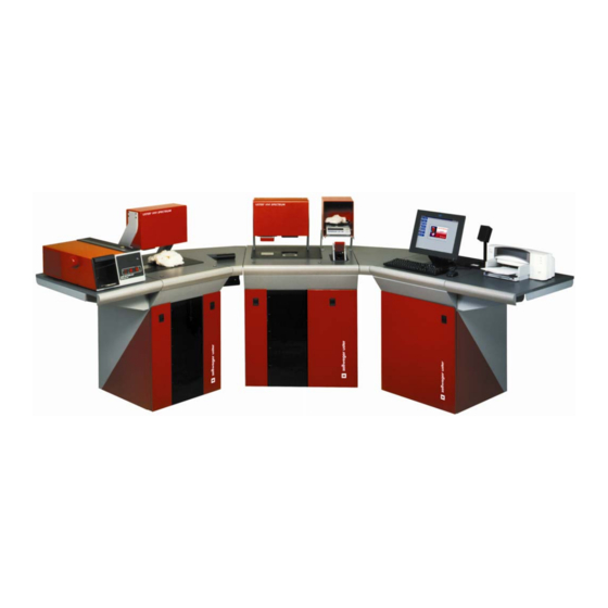
HIGH VOLUME FIBER TEST SYSTEM
Brand:
USTER
| Category:
Test Equipment
| Size: 3 MB
Table of Contents
Table of Contents
5
Chapter 1 Overview
15
Purpose
15
Introduction
15
Visual Cues Used in this Manual
16
Major System Distinctions
17
Hvi Spectrum Equipment
18
Table 1-1: Components and Software
18
System Drawing
20
Figure 1-1: Instrument with ALL Optional Modules
20
Hvi Spectrum System Modules
21
Micronaire Module
21
Length/Strength Module
22
Color/Trash Module
22
Moisture Probe
23
Software Features
23
Error Messages
23
Keyboard Commands
24
Exit
24
Labels
25
Figure 1-2: Crush Hazard Label
25
Figure 1-3: Shear Hazard Label
25
Figure 1-6: HVI SPECTRUM Equipment Label
26
Figure 1-7: HAZARDOUS VOLTAGE Warning Label
26
Chapter 2 Installation
27
General Requirements
27
Electrical Requirements
28
Required Laboratory Conditions
28
Air Requirements
29
Air Quality Requirements
29
Uninterruptible Power Supplies (Ups)
30
Floor Space Requirements
30
Standard HVI SPECTRUM
31
Figure 2-1: HVI SPECTRUM - Standard
31
Hvi Spectrum I
32
Connections
35
Chapter 3 Software Overview
37
Control System
37
Figure 3-1: Main Power Switch
37
Figure 3-2: Power Button/Vacuum Blower Button
38
Software
39
HVI SPECTRUM Main Menu
39
Testing
40
Setup
40
Figure 3-4: Testing Button
40
Figure 3-5: Setup Button
40
Qualiprofile
41
Reports
41
Bale Manager
41
Figure 3-6: USTER® Qualiprofile Button
41
Figure 3-7: Reports Button
41
Figure 3-8: Bale Manager Button
41
Help
42
Quit
42
Figure 3-9: Help Button
42
Figure 3-10: about Screen
42
Figure 3-11: Quit Button
42
Resetting the System
43
Figure 3-12: Computer System RESET Button
43
Chapter 4 Calibration
45
Overview
45
Cotton Calibration
46
Module Calibration
48
Figure 4-1: Main Menu
48
Figure 4-2: Calibration Screen
49
Length/Strength Calibration
50
Figure 4-3: Length/Strength Calibration Menu
50
Figure 4-4: Length/Strength Calibration Dialog Box
51
Length/Strength and Uniformity Calibration
51
Micronaire Calibration
54
Figure 4-5: Micronaire Calibration Menu
54
Calibration Procedures for Micronaire
56
Color Calibration
57
Figure 4-7: Calibration Screen
57
Figure 4-8: Color Reference Values Screen
58
Figure 4-9: Color Calibration Screen - Defined Tile Color
58
Figure 4-10: Color Calibration Screen - Results
60
Trash Calibration
61
Figure 4-11: Calibration Screen
61
Figure 4-12: Calibrate Flash and Trash Screen
62
Procedures for Flash Calibration
62
Procedures for Trash Calibration
63
Figure 4-13: Main Menu - Setup
65
Temperature and Humidity Calibration
65
Figure 4-14: Temperature and Humidity Calibration
66
UV Meter Calibration
67
Chapter 5 System Check
69
Overview
69
System Check Selection Menu
69
Figure 5-1: System Check Button
69
Micronaire
70
Calibration Check
70
Figure 5-2: Main Menu - S
70
Figure 5-3: System Check Test Selection Menu
71
Figure 5-4: System Check Micronaire Screen
72
Calibration Test
73
Length/Strength
74
Calibration Check
74
Figure 5-5: System Check Length/Strength Screen
74
Calibration Test
75
Color/Trash
76
Calibration Check
76
Calibration Test
76
Figure 5-6: System Check Color/Trash Screen
76
Chapter 6 Configurations
77
Introduction
77
System Configuration Screen
77
Figure 6-1: Main Menu - Setup
77
Test Setup Tab
78
Figure 6-2: System Configuration - Test Setup Tab
78
Lot Limits
81
Creating Lot Limits
82
Figure 6-3: Main Menu - Setup
82
Figure 6-4: Lot Limits Screen
83
Figure 6-5: Error Message - Lot Limit Name Already Exists
84
Figure 6-6: Lot Limits Screen - 0 Property
84
Edit Lot Limits
85
Figure 6-7: New Lot Limit Added
85
Figure 6-8: Lot Limits Screen - Edit
85
Figure 6-9: Lot Limit Updated
86
Delete Lot Limits
87
Figure 6-10: Lot Limits Screen - Delete
87
Figure 6-11: "D
87
Measurement Selection Tab
88
General Setup Tab
89
Temperature and RH Tab
90
Retest Tolerance Tab
91
Table 6-1: Standard Equation for SCI - Example
93
Table 6-2: SCI Equation
93
Changing the SCI Equation
94
USTER® SCI Regression Coefficients
93
Chapter 7 Testing Procedures
95
Overview
95
Table 7-1: Instrument Components/Software
95
Testing Sequence Quick Reference
96
Step 1-Access the Main Testing Screen
97
Step 2-Choose from Additional Selections
98
Figure 7-2: Testing Button
98
Figure 7-3: Testing Mode Selection Screen
98
Step 3-Operator Identification
99
Figure 7-4: Operator ID Entry Dialog Box
99
Step 4-Identify the Sample
100
Figure 7-5: Testing Screen
100
Step 5-Perform the Micronaire Test
101
Step 6-Perform L/S and C/T (Optional Module) Tests
103
Exit from Testing
104
Printing the Test Results
104
Determining the Action When Cotton Fails to Meet Lot Limits
105
Figure 7-6: MEASUREMENTO
105
Figure 7-7: Bales out of Tolerance Dialog Box
106
Chapter 8 Reports
107
Introduction
107
Figure 8-1: Reports Button
107
Figure 8-2: Reports Menu Screen
107
Categories
108
Creating Categories
108
Figure 8-4: Reports Screen Menu Options
109
Figure 8-5: Categories Screen
109
Overview of the Category System
110
Changing the Pre-Defined Categories
111
Designing/Deleting/Modifying Reports
112
Type and Format of Test Data
112
Designing a New Report
114
Figure 8-6: Report Design Screen
114
Figure 8-7: Report Design Screen - Lower Section
115
Modifying/Deleting a Report
117
Generating a Report
118
Figure 8-8: Run a Report Screen
118
Graphs
119
Creating a New Graph
119
Figure 8-9: Reports Screen Menu Options
119
Figure 8-10: Graph Design Screen
120
Deleting a Graph
121
Generating a Graph
122
Figure 8-11: Run a Graph
122
Exporting Data
123
Export Data Type
123
Figure 8-12: Export Data Screen
123
Export Options
124
Using the
125
HVI SPECTRUM Database
125
Delete All Data for a Specific Lot
125
Delete Multiple Records for a Lot
127
Chapter 9 Quick Reports
129
Introduction
129
Figure 9-1: Select Quick Report Screen - Individual
129
Figure 9-2: Select Quick Report Screen - Summary
130
Figure 9-3: Quick Report Example
131
Chapter 10 Bale Manager
133
Overview
133
Accessing Bale Manager
134
Figure 10-2: Bale Manager Main Menu
135
Main Functions
136
File
136
Table 10-1: Menu Functions
136
Data Import
137
Figure 10-3: Data Import Screen
137
Exit
139
Figure 10-4: Bale Manager - Duplicate Data Detected
139
Figure 10-5: Status Dialog
139
Configure
140
System Status
141
Figure 10-6: System Status Screen
141
Defining Categories
143
How the Category System Works
143
Number of Categories
144
Why Category Definitions Should Remain the same
144
Defining Categories-Initial Definition
145
Table 10-2: Example Values for Fiber Property Histograms
145
Define Categories to Reflect Inventory
146
Figure 10-7: Define Categories Screen
146
Define Growth Areas
148
Figure 10-8: Define Growth Areas Screen
148
Figure 10-9: Define Growth Areas - Edit Screen
149
Define Proportional/Centered MIX Criteria
150
Figure 10-10: Define/Proportional MIX Criteria Screen
150
Define SCI Calculations
152
Figure 10-11: Define SCI Equation Screen
152
Changing the SCI Equation
153
Length (Inch)
153
Table 10-3: SCI Equation for no Color or Trash Measurements
153
Edit
154
Bale Data
154
Figure 10-12: Bale Data Screen
154
Delete for Lot ID
156
Figure 10-13: Delete for Lot ID Screen
156
Delete for Growth Areas
157
Figure 10-14: Delete for Growth Area Screen
157
Delete MIX History
158
Figure 10-15: Delete MIX History
158
Change Growth Area
159
Figure 10-16: Change Growth Area Screen
159
MIX
160
Make a MIX
160
Active Mixes
161
Figure 10-17: Make a MIX Screen
161
Figure 10-18: Active Mixes Screen
161
Preview/Accept MIX
162
View
162
Figure 10-19: Preview/Accept MIX Screen
162
Figure 10-20: View Inventory Bale Data
163
View Inventory Bale Data
163
Figure 10-21: View MIX History Screen
164
View MIX History
164
Figure 10-22: View MIX History Detail Screen
165
View MIX History Details
165
Figure 10-23: MIX History Histogram Screen
166
View MIX History Histograms
166
Figure 10-24: View MIX History Trends
167
View MIX History Trends
167
Figure 10-25: View MIX History Trends - Date Range / Calendar
168
Chapter 11 Uster® Qualiprofile
169
Introduction
169
Qualiprofile
171
Figure 11-3: Main Menu
171
Figure 11-4: Qualiprofile Main Menu
172
Figure 11-5: Select a Profile Screen
173
Selecting a Profile
173
Designing a Qualiprofile
174
Figure 11-6: T Design of a Qualiprofile
174
Chapter 12 Diagnostics
177
Introduction
177
Diagnostics
178
Figure 12-1: Main Menu - Setup
178
Figure 12-2: Diagnostics Screen
179
Error Log
181
Table 12-1: Description of Diagnostic Function Keys
181
Chapter 13 Maintenance
183
Introduction
183
Cleaning the System
183
As Required
183
After each Shift
183
Daily
184
Calibration Tile Care
184
Cleaning Calibration Tiles
185
Service
186
Chapter 14 Appendix
187
Hvi Spectrum Specifications
187
Length (MM)
187
Disk Information
189
Diskettes
189
Disk Operating System
189
Monitor Information
190
Printer Information
190
Balance Configuration
191
Recommended Lot Limits for Cotton
193
Table 14-1: Recommended Lot Limit Values
193
Transmission Architecture
194
Universal Record Format
196
Length/Strength
198
Uniformity
198
Strength
199
Micronaire
201
Color & Trash
202
Sci
204
Maturity
204
Moisture
205
NEP Count
206
Error Messages
209
Table 14-4: Error Messages
213
Chapter 15 Glossary
215
Chapter 16 Index
225
Advertisement
Advertisement
Related Products
USTER HVI SPECTRUM I
USTER HVI SPECTRUM II
USTER HVI 900
USTER HVI1000
USTER HVIM1000
USTER Categories
Test Equipment
Analytical Instruments
More USTER Manuals
Login
Sign In
OR
Sign in with Facebook
Sign in with Google
Upload manual
Upload from disk
Upload from URL