
Related Manuals for USTER HVI 1000


Summary of Contents for USTER HVI 1000
- Page 1 ® HVI 1000 USTER Instruction Manual HIGH VOLUME FIBER TEST SYSTEM Version: 3.1.3.2 Date: May 2008 Part Number: 255-450-01210 English...
- Page 3 Uster Technologies, Inc. GRANT OF LICENSE: Uster Technologies, Inc. grants the user the right to use the software program on a single computer. Only one copy may be made, solely for backup purposes. This license remains in effect until termination.
- Page 4 The vendor’s liability shall cease if the purchaser or a third party undertakes changes or repairs to the goods without the written consent of Uster Technologies, Inc., or if such goods are resold by the purchaser to a third party without an agreement from the Uster Technologies, Inc.
-
Page 5: Table Of Contents
Table of Contents CHAPTER 1 INTRODUCTION ..........1-1 ................1-1 VERVIEW ................1-2 QUIPMENT 2.1 Monitor................1-2 2.2 Balance ...............1-3 ..............1-3 YSTEM ODULES 3.1 Length/Strength Module ..........1-4 3.2 Micronaire Module............1-5 3.3 Color and Trash Modules ..........1-6 ..............1-7 OFTWARE EATURES 4.1 Error Messages .............1-7 ..........1-7 ISUAL ANUAL ...................1-8... - Page 6 2.1.4 Help/About ............3-7 2.2 Toolbar ................3-8 2.3 ID Bar ................3-8 2.4 Action Area ..............3-8 ................3-9 OFTWARE 3.1 Configuration .............3-10 3.2 Calibration ..............3-11 3.3 System Testing ............3-12 3.4 Module Testing ............3-12 3.5 Report Launcher ............3-13 3.5.1 View Reports ............3-13 3.6 Bale Manager.............3-14 3.7 Diagnostics..............3-14 3.8 Shutdown Testing ............3-15 3.9 Exit................3-15...
- Page 7 CHAPTER 5 CALIBRATION ..........5-1 ................5-1 VERVIEW 1.1 Module Calibration ............5-2 ............5-5 ALIBRATION 2.1 Password Protection............5-6 ..........5-7 ENGTH TRENGTH ALIBRATION 3.1 L/S Cotton Calibration ...........5-7 3.1.1 Setup L/S Calibration Tolerances ......5-7 3.1.2 Setup L/S Calibration References ......5-9 3.1.3 Check Calibration ..........5-10 3.1.4 Cotton Calibration..........5-11 3.2 View Calibration Results..........5-15 ............5-16...
- Page 8 4.5.1 Background Color ...........6-6 4.5.2 Numeric Text ............6-7 ............6-8 ESTING CREEN 5.1 Mode 1 Testing Sequence ..........6-9 5.2 Retesting ..............6-11 ............6-12 ESTING CREEN 6.1 Mode 2 Testing Sequence ..........6-13 6.2 Retesting ..............6-14 ............6-16 ESTING CREEN 7.1 Mode 3 Testing Sequence ..........6-17 7.2 Retesting ..............6-18 ............6-20 ESTING...
- Page 9 5.1 Report................7-14 5.2 Exit................7-14 CHAPTER 8 DIAGNOSTICS..........8-1 .................8-1 URPOSE ..............8-2 IAGNOSTICS ..........8-3 IAGNOSTICS ARDWARE ETUP 3.1 BaleID BCR..............8-3 3.2 Color Head ..............8-4 3.2.1 Find Trash ..............8-5 3.2.2 Load Image ............8-5 3.2.3 Save Image ............8-5 3.2.4 View Trash Settings ..........8-5 3.2.5 Warm Up Color Head ..........8-6 3.2.6 Exit................8-6 3.3 Optics Zero ..............8-7 3.4 Mic Air/Chamber Setup..........8-8...
- Page 10 3.10 Update Firmware ............8-37 CHAPTER 9 REPORT LAUNCHER........9-1 ................9-1 1.1 Menu Bar ..............9-2 1.2 Toolbar ................9-3 1.3 Favorites Bar..............9-3 1.3.1 Configure Your Favorites ..........9-4 1.4 Viewing Area ...............9-5 1.4.1 Report Navigation ...........9-6 .............9-6 EPORT AUNCHER ETUP 2.1 Language ..............9-7 2.2 Set Default Folder ............9-7 2.3 Set Database Connection ..........9-7 2.4 Setup Printer ..............9-8 ...............9-8...
- Page 11 1.5.4 SCI..............12-8 1.5.5 Maturity ...............12-8 1.5.6 Moisture...............12-9 1.5.7 NEP Count ............12-10 1.6 HVI 1000 Record Structure .........12-10 HVI 1000 1.6.1 Summary Format ........12-11 HVI 1000 1.6.2 Nep Record Format ......12-14 HVI 1000 1.6.3 Example Records........12-15 ................12-16 RRORS 2.1 Error Code ...............12-16 2.2 Control Board ............12-17...
- Page 12 4-2: P ..........4-3 IGURE ASSWORD ONFIGURATION 4-3: H ..........4-4 IGURE OMMUNICATIONS 4-4: L ............4-7 IGURE IMITS 4-5: L ............4-8 IGURE IMIT ELECTIONS 4-6: D ..............4-9 IGURE ISPLAY 4-7: S ..............4-9 IGURE IMITS 4-8: HVI O ............4-11 IGURE FFSETS 4-9: D .............4-12 IGURE IAGNOSTICS...
- Page 13 6-5: S – M 3........6-16 IGURE YSTEM ESTING CREEN 6-6: S – M 4........6-20 IGURE YSTEM ESTING CREEN Section 7 7-1: M ........7-2 IGURE ODULE ELECTION CREEN 7-2: LS M ...........7-3 IGURE ODULE ESTING CREEN 7-3: LS R ............7-5 IGURE EPORT ELECTION 7-4: MIC M...
- Page 14 Section 9 9-1 R .........9-2 IGURE EPORT AUNCHER 9-2: R ..........9-3 IGURE EPORT AUNCHER OOLBAR 9-3: F ............9-3 IGURE AVORITES 9-19: C ........9-4 IGURE ONFIGURE AVORITE UTTON 9-4: R ............9-5 IGURE EPORT IEWING 9-5: R ........9-6 IGURE EPORT AVIGATION OOLBAR 9-6: O ............9-7 IGURE...
-
Page 15: Chapter 1 Introduction
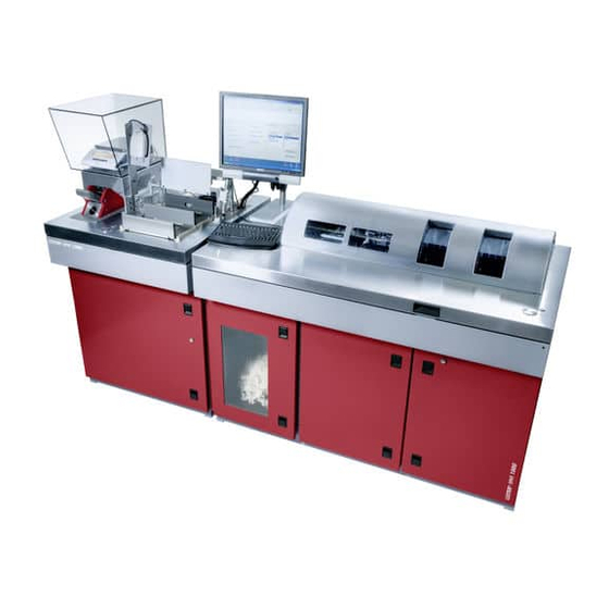
HVI 1000 USTER® Instruction Manual Chapter 1 Introduction Overview HVI 1000 The USTER® (High Volume Instrument for fiber testing) is available in two models, the M1000 and the M700. The major difference between these models is that the M1000 Length/Strength... -
Page 16: Equipment
HVI 1000 USTER® Instruction Manual Equipment HVI 1000 The following features are available on the system: • Monitor • Keyboard • Computer • Hard disk drive loaded with the necessary interface, operations, calculation, and reporting packages • 3.5-inch Floppy Drive •... -
Page 17: Balance
HVI 1000 USTER® Instruction Manual 2.2 Balance A balance is supplied with the system to be used with the Micronaire Module. It comes with documentation from the manufacturer. ANY changes to the balance configuration MUST be performed by a qualified service technician ONLY. -
Page 18: Length/Strength Module
HVI 1000 USTER® Instruction Manual 3.1 Length/Strength Module In the Length/Strength Module, mean and upper half mean lengths and associated uniformities are determined. Strength is obtained by measuring the force required to break a cotton sample of known mass. Elongation, the average length of distance to which the fibers extend before breaking, is also calculated. -
Page 19: Micronaire Module
HVI 1000 USTER® Instruction Manual 3.2 Micronaire Module Micronaire is measured by relating air flow resistance to the specific surface of fibers. An air stream is passed through a known mass of fiber confined in a chamber of fixed volume. -
Page 20: Color And Trash Modules
HVI 1000 USTER® Instruction Manual 3.3 Color and Trash Modules The instrument for measuring color for cotton (lightness and yellowness) is located in the micronaire cabinet. The color and trash tests are performed simultaneously. The color and trash trays, where the operator places the cotton sample (M1000). -
Page 21: Software Features
Once a selection has been entered, the screen reflects the choice and displays step-by-step information the operator needs to proceed. The HVI 1000 software, Reports major software components include the Launcher, Bale Manager (installation optional). -
Page 22: Safety
HVI 1000 system is safe to operate in a normal manner; however, if the equipment is used in a manner not specified by Uster Technologies, Inc. the protection provided by the equipment might be impaired. There are also certain conditions that warrant cautionary statements. - Page 23 HVI 1000 USTER® Instruction Manual A label is located on the comb transport assembly indicating the crush hazard when your hand is in the area of the comb transport. The warning label with the hand/wire/flash indicates that hazardous voltage is behind the doors.
- Page 24 HVI 1000 USTER® Instruction Manual Uster Technologies, Inc. Chapter 1 (3/08) Introduction - Page 1-10...
-
Page 25: Chapter 2 Installation
Report any loss or damage to the carrier immediately. When the system is received or shortly thereafter, an Uster service technician will arrive to complete installation. ATTENTION:... -
Page 26: Moving The Instrument
Instruction Manual 1.1 Moving the Instrument (refer to part 5, this chapter) Due to the weight of the HVI 1000, it is necessary to use a forklift when the instrument must be lifted. The Micronaire cabinet and the length/strength cabinet must be moved separately. -
Page 27: Electrical Requirements
220V AC ±15% (50 to 60 Hz) and requires a separate dedicated 15-amp circuit breaker at the facility’s HVI 1000 system electrical load center. During normal operation, the draws approximately eight (8) amps; the startup current is sufficiently high to require a larger breaker. -
Page 28: Air Requirements
HVI 1000 USTER® Instruction Manual Air Requirements 1. The system requires 100 - 150 psi (700-1034 kPa) of clean, dry, unregulated compressed air. a. The air supply connected to the unit must include an overpressure safety device to ensure that the pressure remains less than or equal to 150 psi (1034 kPa). -
Page 29: Floor Space Requirements
HVI 1000 USTER® Instruction Manual Floor Space Requirements • The Length/Strength cabinet occupies a space of 53.5 inches (136 cm) wide x 30 inches (76.2 cm) deep. • The working surface is 38 inches (96.5 cm) from the floor. HVI 1000 •... -
Page 30: Haped C Onfiguration
HVI 1000 USTER® Instructio n Manual Figure 2-3: M700 L-Shaped Configuration CAUTION: It is important to place the instrument so that the main power cord is easily accessible. In case of emergency it MUST NOT be difficult to disconnect the main power. -
Page 31: Sample Ejection Chute
Instruction Manual Sample Ejection Chute The sample ejection chute located on the back of the Length/Strength cabinet must be connected to a vacuum duct, waste bag or Uster Waste Receptacle (part number 255-010-17180) during operation of the unit. CAUTION: Do NOT reach into the Sample Ejection Chute or leave the chute disconnected during operation. - Page 32 HVI 1000 USTER® Instruction Manual • Host Com Connect the Host COM to the connector labeled COM4, Lava Quattro Port A, on the rear of the computer. • LS Controller Connect the LS Control Board to the connector labeled COM1 on the rear of the computer.
-
Page 33: Ups Requirements
Run time of 10 minutes or greater. Entire System Support (with Vacuum Blower): • Uster Technologies Inc does not offer the option to purchase a UPS to protect the entire HVI1000 system. • It is recommended that entire system UPS units be purchased locally. -
Page 34: Power-Up
HVI 1000 USTER® Instruction Manual Power-Up The following sequence should be followed when powering up the 1000 system: 1. Turn ON the Power Box lower switch. 2. Turn ON the Power Box upper switch. 3. Turn ON the computer. 10 Power-Down... -
Page 35: Chapter 3 System Startup
HVI 1000 USTER® Instruction Manual Chapter 3 System Startup Overview HVI 1000 system is a sophisticated instrument that requires specific instruction and training to be used properly. Only operators that have HVI 1000 received proper training should be allowed to use the system. -
Page 36: Menu Bar
HVI 1000 USTER® Instruction Manual Figure 3-1: Main Menu Note: For proper viewing of the software, ensure that the monitor resolution is set to 1280x1024. 2.1 Menu Bar The M defaults to the system/module testing area. Functionality can be accessed via the toolbar and/or the menu bar. -
Page 37: Actions
HVI 1000 USTER® Instruction Manual 2.1.2 Actions The A item on the menu bar consists of the following: CTIONS ♦ Show Configuration ♦ Show Calibration ♦ Length/Strength ♦ MIC ♦ Color ♦ Trash ♦ Summary/History (toggle-for current testing only) ♦ Eject L/S Sample from bin ♦... - Page 38 HVI 1000 USTER® Instruction Manual menu bar, or use the F5 key to launch the re-enter screen. This screen will display the original bale ID. Enter the new bale ID and click OK. 2.1.2.4 Log Status The Log Status selection allows the current status of the instrument to be viewed.
- Page 39 HVI 1000 USTER® Instruction Manual 2.1.2.7 Clean Log Files The Clean Log Files utility scans files and automatically cleans older files as needed. 2.1.2.8 Export Data This database utility is used to export bale data from system testing into a file. Currently two formats are supported: Simple text file and MS Access database.
- Page 40 If the database does not already exist, a new database will be created as specified in the Path / Filename option. Note: System test data can also be automatically exported after a test completes. Ask your Uster service technician about configuring your system for this functionality. 2.1.2.9...
-
Page 41: View
HVI 1000 USTER® Instruction Manual 2.1.3 View The V item on the menu bar consists of: ♦ Status Bar ♦ Small Trash Image ♦ System Testing ♦ Configuration ♦ Diagnostics ♦ Check/Calibrate ♦ Return ♦ Report Launcher (installation optional) ♦ Bale Manager ♦... -
Page 42: Id Bar
HVI 1000 USTER® Instruction Manual 2.2 Toolbar The toolbar contains icons, from left to right, for the following: Figure 3-6: Toolbar 1. System Testing 2. Configuration 3. Calibration 4. Diagnostics 5. Return 6. Report Launcher 7. Help/About 2.3 ID Bar... -
Page 43: Software
HVI 1000 USTER® Instruction Manual Software HVI 1000 software has six different primary functions: 1. Configuration 2. Check/Calibrate 3. System Testing 4. Module Testing 5. Diagnostics 6. Report Launcher These functions can be accessed via the menu bar selections or the icons on the toolbar. -
Page 44: Configuration
HVI 1000 USTER® Instruction Manual 3.1 Configuration Important operating parameters are defined here. Normally, these choices are made at system startup and retained indefinitely. This menu includes numerous choices for setting up the instrument for system testing. Configuration must be performed before calibration, system testing, or module testing can begin. -
Page 45: Calibration
HVI 1000 USTER® Instruction Manual 3.2 Calibration Calibration or calibration checks are routine procedures normally performed at the start of a shift. When the C icon is ALIBRATION selected, the C is displayed. Some items require a ALIBRATION supervisor password. -
Page 46: System Testing
Report. The Status of testing is displayed toward the bottom of the screen. Note: Refer to the System Testing chapter for detailed information on the procedures to be used for an HVI 1000 system. 3.4 Module Testing The M selection is used when only one of the modules in... -
Page 47: Report Launcher
HVI 1000 USTER® Instruction Manual 3.5 Report Launcher The R allows you to configure, view and print module EPORT AUNCHER and bale data, information from testing, bale classing data, bale count data and summary reports. There are three ways to view a report. -
Page 48: Bale Manager
HVI 1000 USTER® Instruction Manual 3.6 Bale Manager HVI 1000 ANAGER is an optional component of the system. It is used to guide decisions on fiber procurement, facilitate warehousing, control short and long-term variation within and between mixes, predict spinning performance, and prepare reports for review. Data files containing high volume instrument (HVI) test results are imported and assigned to categories. -
Page 49: Shutdown Testing
HVI 1000 USTER® Instruction Manual 3.8 Shutdown Testing At the end of a day of testing we recommend that you turn OFF the printer and monitors, but leave the instrument turned ON. 3.9 Exit HVI 1000 Select File and then Exit to close the application. - Page 50 HVI 1000 USTER® Instruction Manual Uster Technologies, Inc. Chapter 3 (3/08) System Startup - Page 3-16...
-
Page 51: Chapter 4 Configuration
HVI 1000 USTER® Instruction Manual Chapter 4 Configuration Overview The C allows you to define a number of important ONFIGURATION operating parameters. Configuration must be completed prior to calibration or testing procedures. Note: In most cases the configuration selections made when the system is installed are retained indefinitely. -
Page 52: Test Setup
HVI 1000 USTER® Instruction Manual Test Setup This area is primarily used to set options for system testing, including the number of repetitions, whether to apply lot limits or side limits, use grade entry, send data to the host, perform moisture correction of length/strength, and more. -
Page 53: Length/Strength Options
HVI 1000 USTER® Instruction Manual 2.1 Length/Strength Options Perform Moisture Correction of L/S: This selection will use moisture testing values to adjust any values that are related to moisture (Length, Strength, Short Fiber Index (SFI), etc.). L/S Bin Sample Eject: When this is selected the system will always eject the cotton sample whether or not testing has passed. -
Page 54: Defaults
HVI 1000 USTER® Instruction Manual 2.3 Defaults Length Units: English = inch Temperature: Celsius Short Fiber Index (SFI) Type: 0.5in / 12.7mm Moisture: Dry Basis Cotton Type: Upland Trash Identifier: Trash Grade Note: If you select items other than the default, you must select Apply to save the changes. -
Page 55: Test Mode(S) To Use
HVI 1000 USTER® Instruction Manual Enter your selections and click Apply to exit and save the changes. The Status area shows the current settings when communications are enabled. Click Close to exit the window without making any changes. Note: Refer to the appendix for details on host communications transmission architecture. -
Page 56: Mode 3
HVI 1000 USTER® Instruction Manual Length/Strength and Color/Trash are processed ONE BALE at a time. The Length/Strength sampler drums and the Micronaire Color/Trash tray operate the same as for Mode 1. This mode supports overlap of testing so that throughput is increased. -
Page 57: Lot Limits
HVI 1000 USTER® Instruction Manual Lot Limits Lot Limits establish a range of legitimate property values. Lot limits apply to the outcome for a bale in system testing. Lot limits do NOT apply to calibration, module testing, module qualification, or diagnostics. -
Page 58: Selecting Lot Limits
HVI 1000 USTER® Instruction Manual 3.1 Selecting Lot Limits There are two lists of test modes available to choose from. 1. Configured Lot Limits contains the modes which have existing lot limit configuration. When a mode in this list is selected, its lot limit settings are displayed. -
Page 59: Data Display
HVI 1000 USTER® Instruction Manual 3.2 Data Display The Data Display area reflects the color and symbol used for invalid measurements during system testing. The color used for Lot Limits BLUE and the symbol is #. Note: See the System Testing chapter for further details on color/symbol coding of valid/invalid readings. -
Page 60: Tolerance Values To Use
HVI 1000 USTER® Instruction Manual Tolerance Values to Use Place your cursor in the appropriate text box in the Use column, and then type in the desired value. Once you have selected/edited the tolerances you would like used in system testing, click Apply to enable the entire side limit set for the test mode. -
Page 61: Hvi Offsets
HVI 1000 USTER® Instruction Manual HVI Offsets The HVI O item allows you to make small adjustments to FFSETS measured values. Offsets apply to final bale data in system testing only. These offsets do not apply to individual repetitions, calibration, module testing, module qualification, or diagnostics. -
Page 62: Diagnostic Log
All Offset Constants (except Trash Area) MUST remain at 0 unless you are instructed to change one of the constants by an Uster service technician. Trash area should be 1.0; it is a slope rather than an offset. There is no selection to enable/disable offsets however an offset with a value of zero (0) is not altered. -
Page 63: Report Setup
HVI 1000 USTER® Instruction Manual Report Setup This area enables a default report to be set. This report can also be automatically printed upon testing completion. Click the box preceding Automatically Print Reports on Test Completion and click Apply to set this option. -
Page 64: Data Alarms
HVI 1000 USTER® Instruction Manual Data Alarms This area allows you to configure minimum and maximum ranges for data alarms. If a range is exceeded during operations a message box will appear on the screen. Figure 4-11: Data Alarms To disable alarms, set the minimum and the maximum range(s) to 0. -
Page 65: Chapter 5 Calibration
HVI 1000 USTER® Instruction Manual Chapter 5 Calibration Overview All measuring modules MUST be calibrated for initial startup. After calibration, the modules should be calibrated again whenever calibration standards are changed. Operator calibration should be performed for any of the following circumstances: •... -
Page 66: Module Calibration
HVI 1000 USTER® Instruction Manual CAUTION: Make sure your hands, jewelry, clothing, and any loose items are clear of the door that covers the sampler drums before you press the S button that begins the TART cotton sample preparation and measurement process. - Page 67 HVI 1000 USTER® Instruction Manual 2. For each repetition performed: a. If the data is invalid, an error message is displayed, and the rep can be rejected. b. If the data is valid, it is accepted and displayed. The statistics bar is updated with the Mean, Std dev., and %CV value for each...
- Page 68 HVI 1000 USTER® Instruction Manual calibration constants yield final data that pass calibration tolerances. The status of this check is displayed. If Pass, then the calibration data is saved automatically. b. Note that the calibration procedure for color supports the checking of trash calibration (since the trash tile is part of the 6 tile color calibration / check set).
-
Page 69: Alibration
2. Factory Settings 3. Close Calibration 4. Setup Tolerances 5. Setup References 6. View Calibration Results Note: Factory Settings is for use by Uster Service Technicians ONLY and is password protected. Uster Technologies, Inc. Chapter 5 (3/08) Calibration - Page 5-5... -
Page 70: Password Protection
HVI 1000 USTER® Instruction Manual 2.1 Password Protection The following calibration types are password protected: 1. Setup Tolerances 2. Setup References 3. View Calibration Results 4. Factory Settings include the Length/Strength calibration options of Lens to Break, Deflection, Strength-Tare and Short Fiber Index (SFI), and Jaw Timing. -
Page 71: L/S Cotton Calibration
HVI 1000 USTER® Instruction Manual Length/Strength Calibration The length/strength module has one (1) calibration type available: 1. LS Cotton This can be selected to Check Calibration. The L/S Cotton calibration type allows the operator to: ♦ Setup Tolerances ♦ Setup References ♦... -
Page 72: Enu (M700)
HVI 1000 USTER® Instructio n Manual Figure 5-3: L/S Calibration Tolerances Select the Setup Tolerances button to enter the tolerance values for L/S Calibration. Type a valid password into the P screen and click ASSWORD NTRY Type in desired tolerances. -
Page 73: Setup L/S Calibration References
HVI 1000 USTER® Instruction Manual 3.1.2 Setup L/S Calibration References In this area, enter the standard values found on the outside of the calibration cotton boxes. Figure 5-4: Setup L/S Calibration References Select the Setup References button. Enter the values that are listed on the boxes of calibration cottons currently in use. -
Page 74: Check Calibration
HVI 1000 USTER® Instruction Manual 3.1.3 Check Calibration Click the Check Calibration button to launch the C ALIBRATION Click Start to perform a calibration check, or to begin calibration. Figure 5-5 L/S Check Calibration Menu If the calibration check passes, an L/S Calibration is not required. To perform a re-calibration anyway, click Force a Re-Calc. -
Page 75: Cotton Calibration
In order to better understand the theory behind the calibration procedures it is important to understand the instrument/software principles of calibration. HVI 1000 Calibration cottons are used for the USTER® system. Calibration is performed following engineering principles using hardware devices. Adjustments are then made to "within instrument"... - Page 76 HVI 1000 USTER® Instruction Manual However, when there is a fail condition during calibration, changes are made only to those parameters that are critical for calibration to be brought to a pass condition. In other words, no changes are made to those parameters that pass calibration originally.
- Page 77 HVI 1000 USTER® Instruction Manual Highlight LS Cotton in the Calibration Type window. You are instructed to perform Test 1 of 12 for short cotton. To begin the measurement process, place approximately 10 grams of fiber in the sampler drum(s).
- Page 78 HVI 1000 USTER® Instruction Manual 13. The cotton sample beard(s) are discarded automatically. 14. The results are displayed on the screen. 15. After the second, fourth, and sixth tests a window launches asking the operator to refresh the surface of the cotton sample and the sampler door will open.
-
Page 79: View Calibration Results
HVI 1000 USTER® Instruction Manual 3.2 View Calibration Results When any phase of calibration is completed, results can be viewed by selecting the View Calibration Results button on the C ALIBRATION and enter a valid password. Figure 5-6: L/S Calibration Edit Results Check the values for Slope/Offset, Deflection Constant, Breaker Jaw Gap, and Lens to Break. -
Page 80: Micronaire Calibration
HVI 1000 USTER® Instruction Manual Micronaire Calibration The calibration procedure for micronaire involves the regulation of airflow through the micronaire chamber when two calibration cottons (representing low and high micronaire values) are tested. Figure 5-7 Calibration Main Menu If references need to be edited or updated, do the following: 1. -
Page 81: Setup Calibration Tolerances
HVI 1000 USTER® Instruction Manual 4.1 Setup Calibration Tolerances There are no calibration tolerances to be setup for Micronaire Calibration. Clicking the Calibration Tolerance button will launch an error message. 4.2 Setup Calibration References To edit/change the Micronaire Calibration Reference values: 1. -
Page 82: Check Calibration
HVI 1000 USTER® Instruction Manual 4.3 Check Calibration This calibration procedure allows you to calibrate the micronaire unit for low MIC (fine) or high MIC (course) cotton. To access the M from the C ICRONAIRE ALIBRATION ALIBRATION highlight Micronaire in the Module window, then highlight Mic Cotton in the Calibration Type window and click Check Calibration. - Page 83 If this condition persists, the micronaire chamber may need to be resized by an Uster service technician. You can now click Report to view or print the MIC Calibration Report.
-
Page 84: View Calibration Results
HVI 1000 USTER® Instruction Manual 4.3.1 View Calibration Results Figure 5-11: View Mic Calibration Results To view the results: 1. Click the View Calibration Results button (on the M ALIBRATION 2. Enter a valid password and click OK. 3. Select Cancel to return to the C... -
Page 85: Color Tiles Calibration
HVI 1000 USTER® Instruction Manual Figure 5-12: Calibration Main Menu 5.1 Color Tiles Calibration On the C , highlight Color + Trash in the ALIBRATION Module Window, then highlight your choice of Color Tiles or Trash Tiles in the Calibration Type window. -
Page 86: Setup References
HVI 1000 USTER® Instruction Manual To edit/change the Color Tile Calibration tolerance values: 1. Click the Setup Tolerances button to launch the window. 2. Click the text box to place the cursor inside the box. 3. Use the keyboard to type in the appropriate values for Rd and 4. -
Page 87: Check Calibration
HVI 1000 USTER® Instruction Manual 5.1.3 Check Calibration Highlight Color + Trash in the Module Window, then highlight Color Tiles in the Calibration window and click Check Calibration. This will launch the Color Tiles Calibration screen and a trash image window from which you can select Show Trash or Show Image. - Page 88 HVI 1000 USTER® Instruction Manual Place the CENTRAL tile face down on the color head and press (on the Mic cabinet) the Start button The software will indicate when calibration is complete and a PASS condition has been achieved. ATTENTION: Make sure the tiles are observed in the order requested on the screen.
-
Page 89: View Calibration Results
HVI 1000 USTER® Instruction Manual 5.1.4 View Calibration Results Figure 5-16: View Color Calibration Results To view the results: 1. Click the View Calibration Results button (on the M ALIBRATION 2. Enter a valid password and click OK. 3. Select Cancel to return to the C ALIBRATION Uster Technologies, Inc. -
Page 90: Trash Tile Calibration
HVI 1000 USTER® Instruction Manual 5.2 Trash Tile Calibration This selection allows you to calibrate trash only. After the trash tile has been measured, the trash calibration values for the color head is displayed along with the area and count for the standard value, the measured value and the difference between the standard and measured values. -
Page 91: Setup References
HVI 1000 USTER® Instruction Manual To edit/change the Color Tile Calibration tolerance values: 1. Click the Setup Tolerances button to launch the window. 2. Enter a valid password and click OK. 3. Click the desired text box to place the cursor inside the box. -
Page 92: Check Calibration
HVI 1000 USTER® Instruction Manual 5.2.3 Check Calibration Highlight Color + Trash in the Module Window, then highlight Trash Tiles in the Calibration window and click Check Calibration. This will launch the Trash Tile Calibration screen and a trash image window from which you can select Show Trash or Show Image. - Page 93 HVI 1000 USTER® Instruction Manual Note: The software will indicate when calibration is complete and a PASS condition has been achieved. 5. Once calibration is complete and within tolerance you can view or print the Report. 6. Click Finish to return to the C ALIBRATION Note: The Halt button will stop calibration before it is complete.
-
Page 94: View Calibration Results
HVI 1000 USTER® Instruction Manual 5.2.4 View Calibration Results Figure 5-21: Edit Trash Calibration Results To view the Trash Tile Calibration results: 1. Click the View Calibration Results button to launch the window. 2. Enter a valid password and click OK. -
Page 95: Chapter 6 System Testing
HVI 1000 USTER® Instruction Manual Chapter 6 System Testing Overview HVI 1000 system is designed to allow a linear measuring procedure that includes the Length/Strength, Micronaire and Color/Trash Modules. Optional modules available for testing are moisture, NEP, UV, temperature and relative humidity. The streamlined testing procedure allows one operator to perform all tasks;... - Page 96 HVI 1000 USTER® Instruction Manual The upper portion of the Sample Testing area reflects the status of items set in the C . These items include: ONFIGURATION 1. Number of Length/Strength tests to be performed. 2. Number of Micronaire tests to be performed.
-
Page 97: Testing Modes
HVI 1000 USTER® Instruction Manual Testing Modes There are four different testing modes available for system testing. These are selected in System Testing Options of the Test Setup area of Configuration. Each mode has specific options that are (and are not) available. - Page 98 HVI 1000 USTER® Instruction Manual ♦ Uniformity Index – The ratio, expressed in percent, of two length measurements. ♦ Strength – The relationship of the breaking force to the mass of fibers broken, corrected for MIC and modified by calibration constants.
-
Page 99: Reject Nep
HVI 1000 USTER® Instruction Manual ♦ Trash Area – This value represents the ratio of the accumulated area of all the trash particles to the area of the viewing window of the instrument. ♦ Trash Code – This value represents the range where the tested... -
Page 100: Background Color
HVI 1000 USTER® Instruction Manual 4.5.1 Background Color Background color is used for module testing status. The following colors used: 1. GRAY 2. GREEN 3. YELLOW BLUE 4.5.1.1 Gray The module box is GRAY to indicate that testing is finished or that testing for this module cannot yet begin (no text in box). -
Page 101: Numeric Text
HVI 1000 USTER® Instruction Manual 4.5.1.5 Blue The module box background will turn BLUE when the item is out of tolerance for lot limits. 4.5.2 Numeric Text Numeric text is used to indicate testing status. All measurements, except NEP, use an R/T format. R is the number of the current repetition in testing and T is the total number of repetitions required. -
Page 102: Mode 1 Testing Screen
HVI 1000 USTER® Instruction Manual Mode 1 Testing Screen Once you have selected the System Testing button, the S YSTEM is displayed. Mode 1 is used on the M1000 Model. ESTING Figure 6-3: System Testing Screen – Mode 1 Note: The System Testing screen above is shown with all available options. -
Page 103: Mode 1 Testing Sequence
HVI 1000 USTER® Instruction Manual The testing area in the middle portion of the screen reflects the following: 1. The Mic Scale (in grams). As you weigh cotton samples on the balance for testing the weight is reflected in this area. -
Page 104: (M1000)
HVI 1000 USTER® Instruction Manual Read the Bale ID using the bar code reader or enter the Bale ID via the keyboard. Length/Strength - place a cotton sample in each of the sampler drums. Press the S button; the system automatically forms the cotton TART sample beard, the combs slide along the track to the brusher. -
Page 105: Retesting
HVI 1000 USTER® Instruction Manual 15. The test is performed and the cotton sample ejected from the micronaire chamber. The cotton sample can be re-used up to three times. 16. The number of times a cotton sample is tested is determined by the... -
Page 106: Mode 2 Testing Screen
HVI 1000 USTER® Instruction Manual Mode 2 Testing Screen Once you have selected the System Testing button, the S YSTEM is displayed. Mode 2 is used on the M1000 model. ESTING Figure 6-4: System Testing Screen – Mode 2 Note: Depending upon the configuration of your system the above screen may appear differently. -
Page 107: Mode 2 Testing Sequence
HVI 1000 USTER® Instruction Manual The testing area in the middle portion of the screen reflects the following: 1. The 1 Bale ID text box 2. The 2 Bale ID text box 3. The Mic Scale (in grams). As you weigh cotton samples on the balance for testing the weight is reflected in this area. -
Page 108: Retesting
HVI 1000 USTER® Instruction Manual (on the L/S cabinet) Press the L/S Start button (on the Mic cabinet) Press the C/T Start button Remove the cotton sample from the balance and place it into the micronaire chamber. Close the MIC door to measure the micronaire value for the cotton sample, or if Manual Mic Entry is checked, skip this step. - Page 109 HVI 1000 USTER® Instruction Manual If the Length/Strength, Color, or Trash test results indicate that the measurements from the two sides of the bale are not within the tolerance limits, an error message is displayed beside the measured value for the field out of tolerance.
-
Page 110: Mode 3 Testing Screen
HVI 1000 USTER® Instruction Manual Mode 3 Testing Screen Once you have selected the System Testing button, the S YSTEM is displayed. Mode 3 is used on the M1000 model. ESTING Figure 6-5: System Testing Screen – Mode 3 Note: Depending upon the configuration of your system the above screen may appear differently. -
Page 111: Mode 3 Testing Sequence
HVI 1000 USTER® Instruction Manual The testing area in the middle portion of the screen reflects the following: The 1 Bale ID text box 8. The 2 Bale ID text box 9. The Mic Scale (in grams). As you weigh cotton samples on the balance for testing the weight is reflected in this area. -
Page 112: Retesting
HVI 1000 USTER® Instruction Manual 5. Place the remaining part of the left bale cotton sample into the rear of the color/trash tray. 6. Enter the Bale ID for the right cotton sample. 7. Place 8-10 grams of cotton from the right bale cotton sample into the right drum. - Page 113 HVI 1000 USTER® Instruction Manual Discrepant data includes any combination of side limit or lot limit results. Side limits are indicated by a background. Lot Limits are indicated by a BLUE background. Note: Discrepant means the bale has had one (1) Lot Limit or Side Limit result.
-
Page 114: Mode 4 Testing Screen
HVI 1000 USTER® Instruction Manual If a lot limit occurs with a single MIC, only the cotton sample that violated the lot limit needs to be re-measured. If both cotton samples violate a lot limit for MIC, both samples must be re-measured with the left cotton sample measured first. -
Page 115: Mode 4 Testing Sequence
HVI 1000 USTER® Instruction Manual The upper portion of the screen reflects the following: 1. Bale ID 2. Bale Count/Lot 3. Grade (Host Communications) 4. Whether or not Online testing was selected 5. Lot Limits dialog box 6. Whether or not Side Limits are being applied 7. - Page 116 HVI 1000 USTER® Instruction Manual These parts are: • One (1) Sampler Drum • One (1) Color/Trash Tray • One (1) Micronaire Note: See Part 9 this chapter, for complete details on testing procedures. The instructions in this manual have been written using Length/Strength, Micronaire, and Color/Trash modules.
-
Page 117: Retesting
HVI 1000 USTER® Instruction Manual 10. Weigh a +/-10 gram cotton sample on the balance. (of configured valid range) 11. Place the cotton sample in the micronaire chamber and close the door. 12. The test is performed and the sample ejected. -
Page 118: Sample Testing Procedures
HVI 1000 USTER® Instruction Manual Sample Testing Procedures There are four (4) main modules in system testing: 1. Bale ID 2. Micronaire (MIC) 3. Length/Strength (L/S) 4. Color/Trash (C/T) All data and measurements are incorporated into these module tests. (though other sequences... -
Page 119: Micronaire
HVI 1000 USTER® Instruction Manual 9.2 Micronaire Follow the steps listed below for micronaire testing. Pull a tuft of cotton from each side of the bale. Place the cotton sample on the balance to be weighed. If the weight of the cotton sample is between 9.5 and 10.5 grams, the micronaire reading... -
Page 120: L/S, Uniformity, Elongation
HVI 1000 USTER® Instruction Manual 9.3 L/S, Uniformity, Elongation The Length/Strength Module measures two cotton samples simultaneously; it automatically prepares the cotton sample beard, positions the comb in place for the measurement, performs the measurements for length, uniformity, strength, and elongation and discards the excess cotton sample fiber. -
Page 121: Color/Trash
HVI 1000 USTER® Instruction Manual On the M1000 model, the second cotton sample is being brushed while the first cotton sample is being measured. As the second sample is being brushed, the sampler drum doors open for the next samples. After the measurements for the first sample are complete, the second cotton sample is moved to the lens and jaw system for testing. -
Page 122: Exit Testing
HVI 1000 USTER® Instruction Manual When the color/trash hand rises, the first and second observations have been made. The module box keeps count of the number of observations made for each cotton sample and the number that is required for the cotton sample. Example: 2/4 means that two of the four required repetitions have been completed. -
Page 123: Chapter 7 Module Testing
HVI 1000 USTER® Instruction Manual Chapter 7 Module Testing The purpose of this mode of operation is to test individual cotton samples outside the System Testing sequence. The Module Testing mode allows the operator to receive test results for individual observations. - Page 124 HVI 1000 USTER® Instruction Manual To access module testing: Shown with all 1. Highlight your selection in the S list. INGLE ODULE available options. 2. Click the Module Test button. Figure 7-1: Module Test Selection Screen This will launch the selected testing screen.
-
Page 125: Length/Strength Module Testing
HVI 1000 USTER® Instruction Manual Length/Strength Module Testing Length/Strength testing treats each comb as a sequential repetition. The two combs are not averaged. If a comb is inadequate, clicking Reject (M1000) Last Rep will reject the data for both combs... -
Page 126: Ls Module Testing Procedure
HVI 1000 USTER® Instruction Manual 1.1 LS Module Testing Procedure Click the Start button on the screen. Enter the Bale ID by scanning it or typing it in using the keyboard. Place the cotton in the sampler drums and press the S... -
Page 127: Report
HVI 1000 USTER® Instruction Manual 1.3 Report You can select the type of data printed from the test results at the end of the test cycle. The selections alternate between straight data reports and graphs. Figure 7-3: LS Report Selection Click the radio button preceding your desired report selection and click OK. -
Page 128: Micronaire Module Testing
HVI 1000 USTER® Instruction Manual Micronaire Module Testing To access Micronaire Module testing from the M ODULE ESTING 1. Highlight Micronaire in the M list. ODULE ESTING 2. Click the Module Test button. Figure 7-4: MIC Module Testing Screen The Module Testing Screen display is different from the one used for System Testing. -
Page 129: Mic Module Testing Procedure
HVI 1000 USTER® Instruction Manual 2.1 MIC Module Testing Procedure Click the S button on the screen. TART Enter the Bale ID by scanning it or typing it in using the keyboard. Weigh the cotton sample on the balance. The cotton sample must weigh between 9.5 and 10.5 grams. -
Page 130: Report
HVI 1000 USTER® Instruction Manual ATTENTION: A repetition CANNOT be rejected if any Example: Click Report other action is taken first! button, start another bale, exit testing. 2.3 Report You can select the type of data printed from the test results at the end of the test cycle. -
Page 131: Color/Trash Module Testing
HVI 1000 USTER® Instruction Manual Color/Trash Module Testing The Color test is always performed on each cotton sample and the test results displayed in the Rd, +b, and Color Grade columns. Trash results are displayed in Trash Area, Trash Count and Leaf Grade columns. -
Page 132: C/T Module Testing Procedure
HVI 1000 USTER® Instruction Manual 3.2 C/T Module Testing Procedure Click the Start button on the screen. Enter the Bale ID by scanning it or typing it in using the keyboard. Place the cotton sample(s) on the color tray (or on the color head sample glass). -
Page 133: Report
HVI 1000 USTER® Instruction Manual 3.4 Report You can select the type of data printed from the test results at the end of the test cycle. The selections alternate between straight data reports and graphs. Figure 7-7: Color/Trash Report Selection Click the radio button preceding your desired report selection and click OK. -
Page 134: Nep Count
HVI 1000 USTER® Instruction Manual Nep Count 720 NEP Tester This area is used as a data interface with the . The NEP Tester HVI 1000 is an optional instrument available for use with the system. This component is used to count Neps in cotton fibers. -
Page 135: Report
HVI 1000 USTER® Instruction Manual 4.2 Report Click the Report button to launch the Nep report that was setup in beneath the R tab. ONFIGURATION EPORT ETUP Your pre-selected report will launch and can be viewed and printed. 4.3 Exit... -
Page 136: Report
HVI 1000 USTER® Instruction Manual 5.1 Report Click the Report button to launch the UV report that was setup in beneath the R tab. ONFIGURATION EPORT ETUP Your pre-selected report will launch and can be viewed and printed. 5.2 Exit Click Finish to return to the M Uster Technologies, Inc. -
Page 137: Chapter 8 Diagnostics
HVI 1000 USTER® Instruction Manual Chapter 8 Diagnostics HVI 1000 system provides software for testing instrument circuits and components that qualified service technicians use during routine checks, trouble-shooting and maintenance. Purpose The Diagnostics section of the software is provided to enable qualified service technicians to setup and troubleshoot the system hardware. -
Page 138: Diagnostics Menu
HVI 1000 USTER® Instruction Manual Diagnostics Menu Diagnostics allows qualified service technicians to check the condition of the motors and the control boards. Firmware for Length/Strength, Micronaire, and Moisture can also be updated from this area. Figure 8-2: Diagnostics Menu Uster Technologies, Inc. -
Page 139: Diagnostics/Hardware Setup
HVI 1000 USTER® Instruction Manual Diagnostics/Hardware Setup This set of diagnostics allows a qualified service technician to troubleshoot individual motors of the instrument, to test the overall operation of the Motor Controllers, Optics and Air system, and to update the firmware for the Micronaire and the Length/Strength cabinets. -
Page 140: Color Head
HVI 1000 USTER® Instruction Manual 3.2 Color Head The Color Head functionality of Diagnostics allows the operator to test the Grab feature. When Grab is clicked, a picture is taken of whatever is on the window (Tile, Cotton, Newspaper, etc.) to ensure that the camera and flash are operating properly. -
Page 141: Find Trash
HVI 1000 USTER® Instruction Manual 3.2.1 Find Trash This selection allows you to view an image that was previously stored on disk. 3.2.2 Load Image You can type in the filename of an image you would like to view, and click the Loading: button to display it on screen. -
Page 142: Warm Up Color Head
HVI 1000 USTER® Instruction Manual 3.2.5 Warm Up Color Head This tool allows the qualified service technician to ensure that the colorhead is properly warmed up. Figure 8-5: Warm Up Color Head Click the Warm-Up Color Head button located in the color head area of the D . -
Page 143: Optics Zero
HVI 1000 USTER® Instruction Manual 3.3 Optics Zero There are 100 pot wiper locations. This area allows you to search for the best pot setting (median value of all settings). Figure 8-6: Optics Zero Menu Click the Optics Zero button on the D . -
Page 144: Mic Air/Chamber Setup
HVI 1000 USTER® Instruction Manual 3.4 Mic Air/Chamber Setup This selection is used during initial setup. After initial setup, it should only be necessary to use this area once in awhile to verify operations. To setup the Mic air or the micronaire chamber, click Mic Air/Chamber Setup from the D . -
Page 145: Mic Air Setup
HVI 1000 USTER® Instruction Manual 3.4.1 Mic Air Setup Insert the micronaire calibration plug and use your finger to check the Mic Air Reading in the following ways: 1. Click Mic Air Off. 2. Click Measure Mic Tare. Values will appear to the left of the screen. -
Page 146: Check Control Boards
HVI 1000 USTER® Instruction Manual 3.5 Check Control Boards 3.5.1 Mic Control Board This area allows qualified service technicians to check the digital inputs, digital outputs, and voltages of the MIC Control Board. Color hand and tray position can also be diagnosed here. Click the Mic Control... - Page 147 HVI 1000 USTER® Instruction Manual Color Hand Up Color Hand Down Tray End Sensor Tray Mid Sensor 10. Tray Home Sensor If there is a check in the box preceding the sensor name, it indicates that the sensor is ON.
- Page 148 HVI 1000 USTER® Instruction Manual 3.5.1.3 Voltages This area allows you to view the 12-Bit and 8-bit SOC and Analog voltages. Figure 8-9: Mic Control Board Voltages 3.5.1.4 Color Hand and Tray Position ♦ Color Hand Position If you wish to move the color hand up or down, click to place a check mark in the box preceding Color Hand Up and Color Hand Down in the Digital Inputs area.
-
Page 149: L/S Control Board
HVI 1000 USTER® Instruction Manual 3.6 L/S Control Board This area allows qualified service technicians to check the digital inputs, digital outputs, and voltages of the L/S Control Board. Click the L/S Control Board button on the D IAGNOSTICS Figure 8-10: L/S Control Board Menu 3.6.1... -
Page 150: Digital Outputs
HVI 1000 USTER® Instruction Manual Strength Sensor Track Motor Home 10. Length Motor Home 11. Brush Motor Home 12. Drum Motor Home If there is a check in the box preceding a motor sensor name, it indicates that the sensor is ON. -
Page 151: Moisture Control Board (M1000)
HVI 1000 USTER® Instruction Manual Note: If you turn OFF the Power (L/S and Mic) it turns the power off to both cabinets (as well as the blower and 4 smart motors.) If you turn OFF the Main Air (L/S and Mic) it turns the air supply off for both cabinets. -
Page 152: Tare Moisture Channels
HVI 1000 USTER® Instruction Manual 3.7.1 Tare Moisture Channels Click Move Combs to Home or Move Combs to L/S 2 to begin. There are three selections that can be used to tare moisture channels: 1. Tare Left 2. Tare Right 3. -
Page 153: Moisture Control Board (M700)
HVI 1000 USTER® Instruction Manual 3.8 Moisture Control Board (M700) This area allows qualified service technicians to tare moisture channels and perform moisture channel tests. Click the Moisture Control Board button on the D IAGNOSTICS Figure 8-12: Moisture Control Board Menu (M700) 3.8.1... -
Page 154: Moisture Channel Tests
HVI 1000 USTER® Instruction Manual 3.8.2 Moisture Channel Tests This area allows you to do the following: (returns measurements from both combs) 1. Read Data (automatically returns data) 2. Read Data by Closing Front Jaw (returns information with jaw 3. Ready Data by Opening Front Jaw... -
Page 155: Check Motors
HVI 1000 USTER® Instruction Manual 3.9 Check Motors Clicking any of the motor buttons on the D allows IAGNOSTICS you to test and operate the motors independently from the rest of the system. All motor selections are password protected. 3.9.1... - Page 156 HVI 1000 USTER® Instruction Manual 3.9.1.2 Track Motor Status This area of the screen shows the current position and status of the track motor and sensor. 3.9.1.3 Track Motor Position Tests To test the track motor positions that you set previously, click the following buttons: 1.
-
Page 157: Track Motor (M700)
HVI 1000 USTER® Instruction Manual 3.9.2 Track Motor (M700) This area allows you to view the track motor status, test and set track motor positions, and to set the drum, brush, and L/S positions. Select the Track Motor button from the D... - Page 158 HVI 1000 USTER® Instruction Manual 3.9.2.2 Track Motor Status This area of the screen shows the current position and status of the track motor and sensor. 3.9.2.3 Track Motor Position Tests To test the track motor positions that you set previously, click the following buttons: 1.
-
Page 159: Brush Motor
HVI 1000 USTER® Instruction Manual 3.9.3 Brush Motor This area allows you to view the brush motor status, test and set brush motor positions, perform a brush cotton sample test, and test the brush DC motor, comb opener and blower power. Select the Brush Motor button from the D . - Page 160 HVI 1000 USTER® Instruction Manual 3.9.3.3 Set Brush Motor Positions This area of the screen allows qualified service technicians to set the brush motor front position. 3.9.3.4 Brush Motor Position Tests To test the brush motor position previously set, click the following buttons: 1.
-
Page 161: Length Motor (M1000)
HVI 1000 USTER® Instruction Manual 3.9.4 Length Motor (M1000) This area allows you to view the length motor status, and to test and set length motor positions. Select the Length Motor button from the IAGNOSTICS Figure 8-16: Length Motor Menu (M1000) 3.9.4.1... - Page 162 HVI 1000 USTER® Instruction Manual 3.9.4.3 Length Motor Position Tests To test the positions you set previously, click the following buttons: 1. Move Breaker to Home 2. Move Breaker to Comb 1 Front 3. Move Breaker to Comb 2 Front Observe the movements and repeat positioning as necessary.
-
Page 163: Length Motor (M700)
HVI 1000 USTER® Instruction Manual 3.9.5 Length Motor (M700) This area allows you to view the length motor status, and to test and set length motor positions. Select the Length Motor button from the IAGNOSTICS Figure 8-17: Length Motor Menu (M700) 3.9.5.1... - Page 164 HVI 1000 USTER® Instruction Manual 3.9.5.3 Length Motor Position Tests To test the positions you set previously, click the following buttons: 4. Move Breaker to Home 5. Move Breaker to Comb Front Observe the movements and repeat positioning as necessary.
-
Page 165: Ls Comb (M1000)
HVI 1000 USTER® Instruction Manual 3.9.6 LS Comb (M1000) This area allows you to check the status and functionality of the L/S comb. Click the LS Comb button on the D IAGNOSTICS begin. Figure 8-18: LS Comb Menu (M1000) There are four (4) test mode selection available: 1. - Page 166 HVI 1000 USTER® Instruction Manual 3.9.6.1 L/S Step by Step Test 1. Place cotton sample into the sampler drums. 2. Click Initialize System to move the combs into position in front of the sampler drums. 3. Click Load Sample to allow the beard to be collected.
-
Page 167: Ls Comb (M700)
HVI 1000 USTER® Instruction Manual 3.9.7 LS Comb (M700) This area allows you to check the status and functionality of the L/S comb. Click the LS Comb button on the D IAGNOSTICS begin. Figure 8-19: LS Comb Menu (M700) There are four (4) test mode selection available: 1. - Page 168 HVI 1000 USTER® Instruction Manual 3.9.7.1 L/S Step by Step Place cotton sample into the sampler drums. 2. Click Initialize System to move the comb into position in front of the sampler drums. 3. Click Load Sample to allow the beard to be collected.
-
Page 169: Drum Motor
HVI 1000 USTER® Instruction Manual 3.9.8 Drum Motor This area allows you to view the drum motor status, to test and set drum motor positions, move combs, and perform general drum tests. Select the Drum Motor button from the D... - Page 170 HVI 1000 USTER® Instruction Manual 4. Move Drum to Vacuum Fibers 5. Move Drum to Start Comb Doff 6. Move Drum to End Comb Doff 7. Move Drum to Eject Cotton Observe movement and reposition as necessary. 3.9.8.4 Comb Location Tests Test the comb positions by clicking the following buttons: 1.
-
Page 171: Strength Motor
HVI 1000 USTER® Instruction Manual 3.9.9 Strength Motor This area allows you to set gauge positions, view the status of the strength motor, view force voltages, test the vacuum blower and jaws, and setup parameters. Click the Strength Motor button on the... - Page 172 HVI 1000 USTER® Instruction Manual 3.9.9.3 Force Voltages This area allows you to view the SOC and Analog voltages for the following: 1. Tare Voltage 2. Jaw Touch Voltage 3. Current Voltage Notice that the values for Tare and Jaws Touch appear when the breaker jaws are CLOSED.
-
Page 173: Update Firmware
HVI 1000 USTER® Instruction Manual 3.10 Update Firmware Firmware can be updated from the D . Click the IAGNOSTICS Update Mic Firmware, the Update L/S Firmware, or the Update Moisture Firmware button to launch the update window and begin. Figure 8-22: Update Firmware Menu Use Method 1 to update the firmware. - Page 174 HVI 1000 USTER® Instruction Manual Uster Technologies, Inc. Chapter 8 (5/08) System Diagnostics - Page 8-38...
-
Page 175: Chapter 9 Report Launcher
HVI 1000 USTER® Instruction Manual Chapter 9 Report Launcher The R allows you to select, view and print module and EPORT AUNCHER bale data information from testing, calibration, and summary reports. There are three ways to access R EPORT AUNCHER 1. -
Page 176: Menu Bar
HVI 1000 USTER® Instruction Manual Figure 9-1 Report Launcher Main Menu 1.1 Menu Bar Functionality can be accessed via the toolbar and/or the menu bar. The menu bar contains the following options: 1. Report: a. Open: Open a report. b. Editor: Edit a report. -
Page 177: Toolbar
HVI 1000 USTER® Instruction Manual 1.2 Toolbar The toolbar contains the following functionality options (in order): Figure 9-2: Report Launcher Toolbar 1. Open and View Report 2. Report Editor 3. Close the Current Report 4. Setup Printer 5. Configure Your Favorites 6. -
Page 178: Configure Your Favorites
HVI 1000 USTER® Instruction Manual 1.3.1 Configure Your Favorites Select the Configure Your Favorites icon from the toolbar. This will launch the Configure Favorite Button window. Figure 9-4: Configure Favorite Button Use the down-arrow and select a Favorite Button number from the drop-down list. -
Page 179: Viewing Area
HVI 1000 USTER® Instruction Manual 1.4 Viewing Area The viewing area displays all selected reports. Figure 9-5: Report Viewing Uster Technologies, Inc. Chapter 9 (3/08) Report Launcher - Page 9-5... -
Page 180: Report Navigation
HVI 1000 USTER® Instruction Manual 1.4.1 Report Navigation Figure 9-6: Report Navigation Toolbar The report display consists of a report and a toolbar. Use the toolbar to print, zoom in or out, navigate through multiple pages, or search for text. -
Page 181: Language
HVI 1000 USTER® Instruction Manual 2.1 Language Select the O on the menu PTIONS bar, and then select Language to set the operating language for program. Default is English. Figure 9-7: Options Menu 2.2 Set Default Folder Select the O... -
Page 182: Setup Printer
HVI 1000 USTER® Instruction Manual Figure 9-9: Set Database Connection 1. Click to darken the radio button preceding your selection of MS Access or SQL Server. 2. Ensure that the Database Location is correct. 3. Click OK. 2.4 Setup Printer... -
Page 183: Open And View Report
HVI 1000 USTER® Instruction Manual 3.1 Open and View Report There are two ways to open a report: 1. Menu Bar: Use the Open selection. 2. Toolbar: Click the Open and View a Report icon. When you make one of the above selections, the Select a Report window will launch. -
Page 184: Close The Current Report
HVI 1000 USTER® Instruction Manual Select a report from the list and then click the Open button. This will launch the Report Parameters window. Figure 9-13: Report Parameters Window The Report Parameters Window allows you to select filters for your selected report. -
Page 185: Pre-Configured Reports
HVI 1000 USTER® Instruction Manual Pre-Configured Reports The following report templates are included in the Report Launcher program. Each of these templates can be custom configured for frequent use. Report Group Report Type Individual Report System Testing Summary Report Fibrogram Report... - Page 186 HVI 1000 USTER® Instruction Manual Report Group Report Type Strength Histogram Report LS Module Testing (Cont.) Moisture Histogram Report Grade Histogram Report Temperature Histogram Report RH Histogram Report Custom Report Color/Trash Module Testing Individual Report Summary Report Color Distribution Report...
-
Page 187: Chapter 10 Maintenance
HVI 1000 USTER® Instruction Manual Chapter 10 Maintenance HVI 1000 system has been designed to reduce maintenance to a minimum. However, to keep the instruments in top condition, there are a few tasks that must be performed routinely. Daily Maintenance •... -
Page 188: Lint/Waste Box Maintenance
HVI 1000 USTER® Instruction Manual — Lift the cover of the Length/Strength cabinet and vacuum all areas under the cover. Pay particular attention to cleaning the comb track area. Vacuum all areas of the cabinet. — After cleaning, close all doors and covers to their original positions. -
Page 189: Calibration Tiles
Rd or +b is noted while testing, calibration tile condition is responsible. Uster recommends that users follow the guidelines below. • The tile set assigned with the unit should STAY with the unit. The tile set will normally maintain its calibration value throughout the life of the instrument. -
Page 190: Cleaning Calibration Tiles
Never handle the tiles in a manner that will place fingerprints on the color surface. • Uster recommends the tile set be cleaned on a periodic basis, depending upon use and conditions. Usually every 2 to 3 months is sufficient. -
Page 191: Service
Factory service is available at the home office, and field service is available worldwide. Contact Uster Technologies, Inc. Uster Technologies, Inc. will gladly provide technical assistance by telephone, fax, or email. Refer to the title page of this manual for the appropriate numbers/addresses. - Page 192 HVI 1000 USTER® Instruction Manual Uster Technologies, Inc. Chapter 10 (3/08) Maintenance - Page 10-6...
-
Page 193: Chapter 11 Glossary
HVI 1000 USTER® Instruction Manual Chapter 11 Glossary +b — The part of Hunter's Scale that indicates yellowness. Cotton ranges from 4 to 18. # Break Points — The number of readings taken on the stress-strain curve. Alphanumeric — Numbers and alphabetical characters on a keyboard in upper or lower case. - Page 194 HVI 1000 USTER® Instruction Manual Cursor — A special symbol seen on the monitor screen; a flashing underline or box, that indicates the position where the next character will be entered. Data Files — A file created within an application. In this case,...
- Page 195 HVI 1000 USTER® Instruction Manual Floppy disk — A device used for storing data. A floppy disk can be inserted in and removed from a floppy disk drive (typically 3.5 or 5.25 inches in diameter). Often used to backup data or to move data from one computer to another.
- Page 196 HVI 1000 USTER® Instruction Manual Length Standard — The metal comb provided with the instrument that is used to measure the distance from the comb transport's home position to the center of the optics. Listings — The reports that are generated by the software. There is usually a choice to display the listing on the screen or to generate a hard copy from the printer.
- Page 197 HVI 1000 USTER® Instruction Manual Observations — The number of individual tests made on a sample. During system testing, the values displayed, printed, and/or sent to a computer are averages of the number of observations made on the sample. On-line — The computer directly controls the equipment or devices that respond to the user's commands.
- Page 198 HVI 1000 USTER® Instruction Manual Sample — The cotton fiber mass to be tested. For micronaire measurements, it must be a certain weight; for length, strength, uniformity, and elongation measurements, it must be in the form of a beard. SCI — Spinning Consistency Index is a calculated value based on a regression equation that takes into account all HVI properties and calculates one value to be used on each sample tested.
- Page 199 HVI 1000 USTER® Instruction Manual Status — The menu where the parameters that affect the program components are defined. The items on these menus are normally defined when the system is first set up and remain unchanged indefinitely. Str — Strength.
- Page 200 HVI 1000 USTER® Instruction Manual Trash Count — The number of individual particles of trash in the cotton sample that are 0.01 inch in diameter or larger. Trash Grade – This value is measured by the Trash Module and can consist of up to four alphanumeric characters.
-
Page 201: Chapter 12 Appendix
HVI 1000 USTER® Instruction Manual Chapter 12 Appendix Host Communications 1.1 Spectrum Support HVI 1000 system will support the HVI Spectrum Universal Record Format (URF) Functionality Means of Observation Record Set for System Testing only. This transmission will be across a 9-pin serial port and can be used with or without LabExpert Support. -
Page 202: Record Structure
HVI 1000 USTER® Instruction Manual 1.3 Record Structure All HVI records are divided into three sections: 1. Head – identifies the instrument, date and time. 2. Body – highlights the data. 3. Tail – identifies the lot limits, re-tests and a validation checksum. - Page 203 HVI 1000 USTER® Instruction Manual Highlights from these records are: All records start with a standard header, which is discussed in the Universal Record Header Format. The record length is variable. The data is transmitted as ASCII characters. In other words, the number 12.5 will be transmitted as four characters, namely “1"...
-
Page 204: Universal Record Header Format
HVI 1000 USTER® Instruction Manual 1.4 Universal Record Header Format HVI 1000 All records transmitted from an instrument will contain a header that describes the information contained within the record. This record header follows: Instrument Type: HVI 1000 HVI 1000 : Record is from an Instrument. -
Page 205: Record Body-Type Formats
HVI 1000 USTER® Instruction Manual 5. Date (dd-mmm-yy), where dd is day, mmm is month [JAN, FEB, MAR, APR, MAY, JUN, JUL, AUG, SEP, OCT, NOV, DEC], and yy is the last two digits of the year. 6. Time (xx:xx), 24-hour format 1.5 Record Body-Type Formats... -
Page 206: Micronaire
HVI 1000 USTER® Instruction Manual Mean of Observations Field Description Size/Type Identifier 40 alphanumerics Sample ID 40 alphanumerics Length x.xxx (inches for English units), or xx.xx (mm for Metric units) Length Retest R or n Length Lot Limit L or n Uniformity xx.x... -
Page 207: Color & Trash
HVI 1000 USTER® Instruction Manual Mean of Observations Field Description Size/Type Identifier 40 alphanumerics Sample ID 40 alphanumerics Micronaire x.xx Micronaire Lot Limit L or n 1.5.3 Color & Trash Individual Observation Field Description Size/Type Identifier 40 alphanumerics Sample ID... -
Page 208: Sci
HVI 1000 USTER® Instruction Manual Trash Particle Count Trash Area xx.xx Trash Area Lot Limit L if rejected or n Trash Code Trash Code Lot Limit L or n 1.5.4 Mean of Observation Field Description Size/Type Identifier 40 alphanumerics Sample ID... -
Page 209: Moisture
HVI 1000 USTER® Instruction Manual 02 Mean of Observations Field Description Size/Type Identifier 40 alphanumerics Sample ID 40 alphanumerics Maturity x.xx Maturity Lot Limit L or n Reserved No characters Reserved No characters Reserved No characters 1.5.6 Moisture Individual Observation... -
Page 210: Nep Count
HVI 1000 USTER® Instruction Manual 1.5.7 NEP Count Note: The NEP data is only transmitted at the end of the current set of Bales for a Lot ID. NEP data is sent for the entire Identifier. Hence, the Sample ID will be blank and the data will account for all the Sample IDs that have the specified Identifier. -
Page 211: Hvi 1000 Summary Format
HVI 1000 USTER® Instruction Manual HVI 1000 1.6.1 Summary Format Below is a table describing the format for the HVI1000M Summary Record Creation. Please note that: TF – Total Field Count RS – Record Section and tries to highlight as to which section the Record is part of;... - Page 212 HVI 1000 USTER® Instruction Manual TF RS SF Field Name Format Comment Width 99.99 moisture corrected Metric (mm) – can be moisture corrected 17 B 9 99.9 Uniformity– can be moisture corrected 18 B 10 SFI 99.9 Short Fiber Index– can be...
- Page 213 HVI 1000 USTER® Instruction Manual TF RS SF Field Name Format Comment Width = Micronaire = Trash ID = UV = Nep = Spare Note: Between Sides takes precedence over Lot Limits if a quality factor is a retest for both.
-
Page 214: Hvi 1000 Example Records
HVI 1000 USTER® Instruction Manual HVI 1000 1.6.2 Nep Record Format The NEP data is only transmitted at the end of the current set of Bales for a Lot ID Below is a table describing the format for the HVI1000M Nep Record Creation. - Page 215 HVI 1000 USTER® Instruction Manual TF RS SF Field Name Format Comment Width Note: Between Sides takes precedence over Lot Limits if a quality factor is a retest for both. 17 T 1 Check Sum Decimal XOR of all the previous data.
-
Page 216: Errors
HVI 1000 USTER® Instruction Manual Errors The Error Handle screen is divided into four basic areas: 1. Error Code 2. Control Board 3. Message Box 4. Options for Recovery Figure 12-1: Error Handle Screen Error Code Each control board has specific error codes that are associated with it. -
Page 217: Control Board
HVI 1000 USTER® Instruction Manual Control Board The control board text box indicates which (if any) control board/module has caused the error. • L/S (Length/Strength) • MIC (Micronaire) • C/T (Color/Trash) • Miscellaneous (Other) Message Box The message box area contains an explanation of the error. Example: Drum failed to move “... -
Page 218: Essages
HVI 1000 USTER® Instruction Manual Error Messages The following table contains numbered error messages. Rows that have more than one number indicate that the error could appear in different locations however the action for both errors is the same. Length/Strength Control Board... - Page 219 HVI 1000 USTER® Instruction Manual Length/Strength Control Board Error Error Code Error Code Code Front Jaw NOT Open Before Test. 1. Check to insure that there is an adequate air supply. Rear Jaw NOT Open Before Test. 2. Go to L/S CTRL Board Front Jaw NOT Closed For Test.
- Page 220 HVI 1000 USTER® Instruction Manual Length/Strength Control Board Error Error Code Error Code Code 16/19 Track Motor Fails To Move. 1. Restart the HVI Program. 2. Go to L/S CTRL Board 17/20 Track Motor Position Error. Diagnostics and turn the...
- Page 221 HVI 1000 USTER® Instruction Manual Length/Strength Control Board Error Message Action Code 24/27 Length Motor Fails To Move. 1. Check to make sure all of the cables to the Length Motor are 25/28 Length Motor Position Error. connected at the motor and the power box.
- Page 222 HVI 1000 USTER® Instruction Manual Length/Strength Control Board Error Message Action Code 32/35 Brush Motor Fails To Move. Go to L/S CTRL Board Diagnostics and turn the Brush 33/36 Brush Motor Position Error. Motor ON/OFF using the buttons in the Digital Inputs column.
- Page 223 HVI 1000 USTER® Instruction Manual Length/Strength Control Board Error Message Action Code Drum Motor Power OFF Error. Go to Drum Motor Diagnostics and turn the Drum Motor OFF and check the status byte. If not responsive may be a problem with the motor, cable or sensor.
- Page 224 HVI 1000 USTER® Instruction Manual Length/Strength Control Board Error Message Action Code Strength Motor Fails To Move. 1. Go to Strength Motor Diagnostics and move the motor FORWARD/REVERSE to see if it is functional. 2. Check for loose cable connection to the power box.
- Page 225 HVI 1000 USTER® Instruction Manual Length/Strength Control Board Error Message Action Code Too Much PULL Force -- Value of 1. Go to Strength Motor A/D=%1 (Valid Range: %2) Diagnostics and learn gauge position. Also, check sensor Too Much PUSH Force -- Value of...
- Page 226 HVI 1000 USTER® Instruction Manual Length/Strength Control Board Error Message Action Code Front Jaw NOT Open. See 7 through 10 above. Rear Jaw NOT Open. NOT in Strength Sensor. 1. Check that sensor is clean and free of obstruction. 2. Go to Strength Motor Diagnostics and learn gauge position.
- Page 227 HVI 1000 USTER® Instruction Manual Micronaire Control Board - Color/Trash Module Error Message Action Code Tray Position Sensor Error. Go to MIC CTRL Board Diagnostics. Utilize the Color Head UP Sensor Error. appropriate buttons in the Not Used Digital Outputs columns to check Color Head DOWN Sensor Error.
- Page 228 HVI 1000 USTER® Instruction Manual Miscellaneous Windows Software Area Error Message Action Related Code Message Windows ERROR Memory Allocation Exit program and restart computer. Software for Image 0 “ Memory Allocation for Image 1 “ RAM Test Failed. Turn power off to computer and then restart computer and program.
- Page 229 HVI 1000 USTER® Instruction Manual Miscellaneous Windows Software Area Area Area Related Area Related to Related Related to Message Message Message Message “ Test of Pattern 2 Restart program. Failed. “ File VP.CFG Not Copy file from the HVI directory Found.
- Page 230 HVI 1000 USTER® Instruction Manual Uster Technologies, Inc. Chapter 12 (7/07) Appendix - Page 12-30...
-
Page 231: Chapter 13 Index
HVI 1000 USTER® Instruction Manual Chapter 13 Index Module · 5-2 Save · 5-4 Short Cotton · 5-12 Trash Tile · 5-26 Action Area · 3-8 Calibration Tiles Actions · 3-3 Maintenance · 10-3 Air · 2-4 Close Testing Supervisor · 3-5 Color Coding ·... - Page 232 HVI 1000 USTER® Instruction Manual Connections Peripherals · 2-7 Controllers · 2-7 Edit Cotton Calibration Results · 5-15 Calibration · 5-11 Password · 4-3 Reports · 3-13 Long · 5-14 Edit Calibration Results Cotton Type Upland · 4-4 Color Tiles · 5-25 Create Trash ·...
- Page 233 HVI 1000 USTER® Instruction Manual Image · 5-29 Main Menu · 3-2 Installation · 2-1 Reports · 9-1 Investigate Software · 3-1 Diagnostics · 8-1 Maintenance · 10-1 Calibration Tiles · 10-3 Clean System · 10-1 Daily · 10-1 Vacuum Box · 10-2...
- Page 234 HVI 1000 USTER® Instruction Manual Print Report · 7-5, 7-8 Binoculars · 9-6 Selection · 7-2 Close · 9-3, 9-10 Modules · 1-3 Configuration · 9-6 Color/Trash · 1-6 Configure · 9-3 Length/Strength · 1-4 Configure Favorites · 9-4 Micronaire · 1-5 Database ·...
- Page 235 HVI 1000 USTER® Instruction Manual Modules · 6-24 Micronaire · 6-10, 6-23 Samples Mode 1 · 6-9, 6-21 Test · 6-2 Mode 3 · 6-12, 6-13, 6-16, 6-17 Save Procedures · 6-24 Calibration · 5-4 Result List · 6-3 Save Image Retest ·...
- Page 236 HVI 1000 USTER® Instruction Manual Warm Up Color Head · 8-6 Uster Technologies, Inc. Chapter 13 (3/08) Index - Page 13-6...
- Page 237 Knoxville, Tennessee 37919 USA Phone +1 865 588-9716 +1 865 588-0914 utuspct@uster.com Uster Technologies AG Wilstrasse 11 CH-8610 Uster / Switzerland Phone +41 43 366 36 36 +41 43 366 36 37 www.uster.com sales@uster.com 255 450-01210 © Copyright 2008 Uster Technologies, Inc.
Need help?
Do you have a question about the HVI 1000 and is the answer not in the manual?
Questions and answers